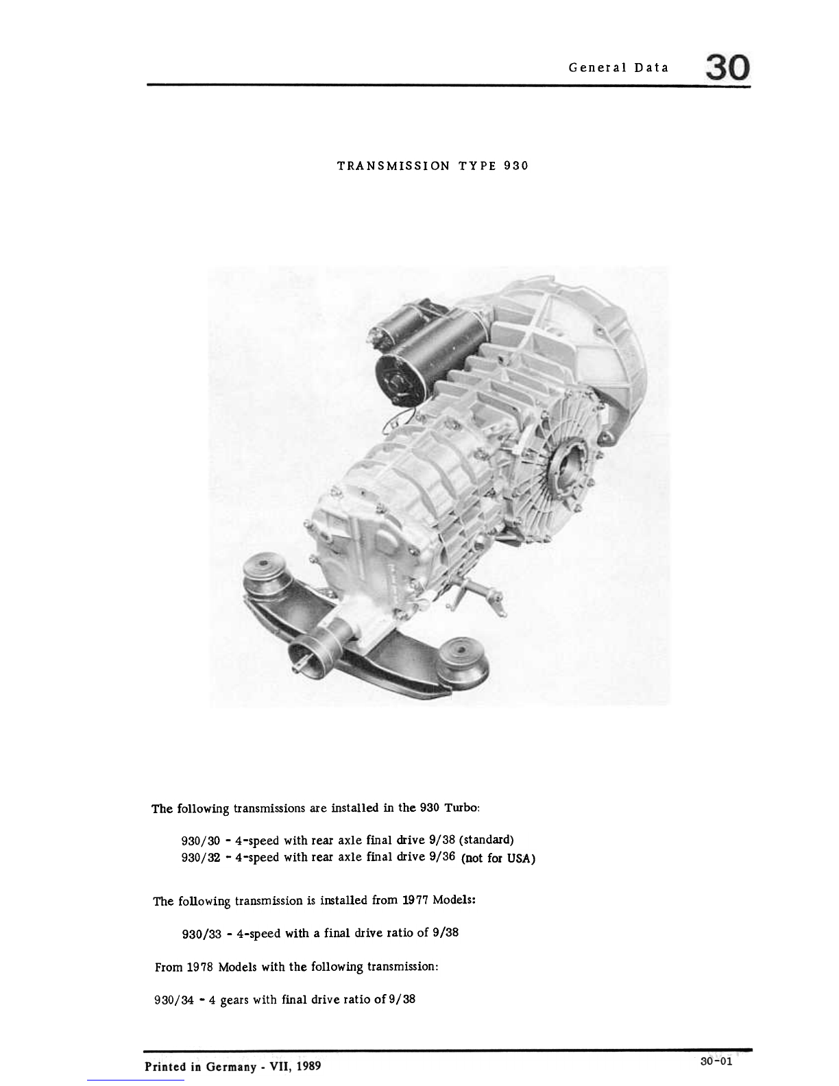
Porsche 930 TURBO - 1989 GENERAL DATA User manual

General Data
TRANSMISSION TYPE 930
The following transmissionsare installed in the 930 Turbo:
930/30 -4-speed with rear axle final drive 9/38 (standard)
930/32 -4-speed with rear axle final drive 9/36 (not for USA)
The following transmissionis installed from 1977Models:
930/33 -4-speed with a final drive ratio of 9/38
From 1978Models with the following transmission:
930/34 -4 gears with final drive ratio of9/38

Generaldata 911 turbo
Five-speed transmission G50/50
88-227
A new five-speed transmission has been installed in the 911 Turbo worldwide from Model 89 onward.
This gearbox corresponds to the G 50/00 Carrera gearbox with regards to construction and repair.
The gearbox has been reinforced, however, and the transmission ratios modified to suit the
high engine performance of the turbo engine.
Refer to the Carrera workshop manual (Page 30-0102) for maintenance information.
Five-speed transmission G50/50
Printed in Germany -VII, 1989
30-02

General Data
MANUAL TRANSMISSION TORQUE SPECIFICATIONS
Location Designation Threads Material Torque
NM (kpm)
Drive shaft Nut M 30xl.5 8.8 210 -230
(21.0 -23.0)
Drive shaft Nut M20xl.5 C 35 V 160-180
(16-18)
Driven shaft Nut M24xl.5 8190-100
(19-20)
Stub axle
Stub axle Stretch bolt
Hex hd screw M IOxl.5
MIOu. 5 8.8
8.8 (2. 6 -3. 0)
(3. 0 -4. 6)
26-30
39-46
Transm. case Vent M 14xl.5 9 S 20 K 20-30
(2 -3)
Gearshift rod Conicalscr. M 8xl.25 8.8 23-26
(2.3-2.6)
Shiftcover Mid-grip nut M 8xl.25 X 12 Cr
No18.8 22-25
(2.2-2.5)
Backuplight
switch
I
Gear housing M18xl.5 MS 25-35
(2.5-3.5)
I
Gearshift
forks M6xl.O 8.8 9-11(0.9-1.1)
Hex nut
M 8xl.25 822-25
(2.2-2.5)
I
Clamp, gears, transm.I
case, front and side
covers
Hex nut
Shift lock,
transm. case Hex hd screw M lOxl.5 8.8 15-18
(1.5-1.8)
24-26
(2.4-2.6)
Hexhd screw M 8xl.25 8.8
Selector
forks
11.9 135-140
(13.5-14)
Ring gear,
differential Hex hd screw M12xl.25
12.9 150-160
(15-16)
Hex hd screw M12xl.25
5t 37-5.8 20-25
(2-2.5)
Plug with
magnet M24x1.5
Con. 1:16
Transm. case
oil drain
5.8 20-25
(2-2.5)
Plug M 30x1.5
Con. 1:16
Gear housing
Oil filler
5.8 20-25
(2-2.5)
Plug M 16xl.5
Reverse gear
Lock
Technical Data 30-03
Printed in Germany -IV. 1981

Location Designation Threads Material Torque
Nm (kpm)
I
Guide tube Capscrew M6xl.O 8.8 8-10
(0.8-1.0)
Clutch and
startergear Capscrew M8xl.O 8.8 20-'-5
(2.0-2.5)
Starter Hex nut MlOxl.5 846-50
(4.6-5.0)
Mech.controls
Holderto base Hex hd screw M6 8.8 6
(0.6)
Baseto tunnel Sockethead
capscrew M8 8.8 21
(2.1)
ICon. screwin
shift rod end Con. screw M8 8.8 15
(1.5)
I
COIl. screw in
coupling Con. screw M8 8.8 15
(1.5)
Clamp Hex hd screw M8 8.8 25
(2.5)
30-04 Technical Data Printed in Germany

General
GeneralData Manual Transm. 930/30, 930/32. 930/33 and
930/34
Ratio
1st gear
2nd gear
3rd gear
4th gear
Reverse
16/36 i = 2.25
23/30 i = 1.3043
28/25 i = 0.8929
32/21 i = 0.6563 (32/20 i = 0.625)
16/39 i = 2.4375
Climbing in 0;0
abo
1st
2nd
3rd
4th
Spiralteethbevelgearwheels
Finaldrive
Final drive ratio
9/38 i = 4.222 (optional 9/36
9/38 i = 4.222
9/38 i = 4.222
= 4)
1976models
1977models
1978 models to 1981 models
Via double joint shaftsto rear wheels
Powertransmission
53 kg
Transmissionweight
(dry) w/0 starter
Approx. 3.7 1SAE90 oil of API Classification
GL5 (or Mil-L 2105 B)
Filling capacity
Note: Deviating values for transmissiontype 930/34 are in brackets.
30 -05
Specifications
Printed in Germany -IV. 1981
ve
100
47
27
16
gear
gear
gear
gear

General Data
TechnicalData
Printed in Germany -III. 1978 30-07

1
-III, 1978Printed in Germany Removing and Installing Clutch Disc 30 -1

30 Clutch, Control
Removing andInstalling Clutch Disc Printed in Germany
30 -2

Clutch, Control
Notes when
No. Description I
Qty. Remarks
Removing Installing
1Clutch bolts 6Unscrew evenly Tightenevenlyand
diagonally torque:2.0-2.5 mkg
(14 -18. 5 ft Ibs)
la Clutchbolts
DIN 931 from
Trans. No. 776
0013 or 776 1011
9Unscrewevenly Tightenevenlyand
diagonally. torque: 2,0-2, 5 mkg
(14 -18, 5 ft Ibs)
2Washer 6Replace, if needed
3Ring gear 1
Check for wear
4Pressureplate 1
5Throwout bearing 1 Don't wash. Wipe
with dryrag. Coat
guide tube contact
surface with MoS
lubricant. 2
Don't subject to
pressure-danger
of damage!
6Clutch disc Check for wear.
Center with clutch
centering tool 9102
1
Removing and Installing Clutch Disc 30 -3
Printed in Germany -IV, 1981

Clutch, Control
REMOVING AND INSTALLING
Removing Note
1. Hold flywheel with toothed segmentP201 a
and spacersleeve. Make sure that spacersleeve
fits engine with adequate clearance.
Clutch linings cannot be replaced.
If applicable, the entire disc is to be replaced.
2. Loosenbolts holding clutch pressureplate to
flywheel evenly and diagonally one or two
threads, until the spring pressurestops(pre-
vents distortion on clutch pressureplate).
5. Checkdiscwithlining for lateral runout.
Permissiblelateral runouton225mm .
diameterismax. 0.6 mm.
CHECKING CLUTCH DISC
1. Checkteeth. The clutchdisc mustmove
easilyin axial direction ondrive shaftwith-
outradialplay.
2. Check rivets. Replace clutch disc if in
doubt.
3. Check clutch lining. If clutch lining hasoil
spots, is burnt, torn or worn at spots, install
a newdisc.
4. Checklining thickness.Thicknessof di'lc
+
with rivetedlining (notension)is10.1 -
0.3 mm. Wearlimit (notension)is 8.5 mm
for symmetricalwear.
Printed in Germany
Removing and Installing Clutch Disc
30 -4

Clutch, Control
CHECKING CLUTCH PRESSURE
PLATE/DISC
The MFZ clutch pressureplate from Fichtel and
Sachsis not designed for reconditioning or repairing.
The inspection is limited to dry cleaning and
removing dust with compressedair and emery
cloth, and a thorough visual! examination.
1. Cleanclutch. If necessary.cleanbearing
surfaceofpressureplate with emerycloth.
Removeburntspotsbypolishing. Cleanentire
assemblythoroughlywithcompressedair.
2. Check endsof diaphragm springsfor traces
of wear from clutch releasebearing. Wear
up to a depth of 0, 3 mm is not serious.
4. Checkspringconnectionsbetweenpressure
plate andcoverforcracks. Checktightness
of rivet connections.Replacepressureplates
withdamagedorlooserivets.
3. Check friction surface of pressureplate for
cracks, burnt spotsandwear. Check with
steel ruler. Pressureplates which are tapered
up to 0,3 mm toward inside, can still be
used(check with feeler gauge blade).
-I, 1976 Removing and Installing Clutch Pressure Plate and Disc 30 -5
Printed in Germany

30 Clutch,Control
Installing
1. After cleaning. check clutch contact surface
of flywheel for wear. If necessary, machine
surface and smooth with emery cloth. Replace
the flywheel, if necessary.
2. Lubricateneedlebearingin flywheelwith
about1 cm3 (1,5 grams)of MoS2grease.
3. Install clutch with specialtool 9102to
centerin flywheel.
4. Centerclutchpressureplate onflywheel.
5. Tighten bolts evenly and diagonally to prevent
distortion on cover. Tighten bolts to speci-
fied torque. UseSpecial Tool P201 a and a
spacing sleeve to hold the flywheel.
30 -6 Printed in Germany
Removing and Installing Clutch PressurePlate and Disc

Clutch. Controls
ADJUSTING CLUTCH FROM 1977 MODELS (with clutch servo on transmission)
Note
Becauseof the clutch servo it is no longer
possibleto check the clutch play exactly at the
clutch pedal. This is why the clutch play of
cars with a servo clutch hasto be checked at
the transmissionadjusting lever.
Check and adjust clutch, see Repair Manual 911,
Main Group 7 -Page 2.1 -2/3.
30 -7
Printed in Germany -II. 1976

DISASSEMBLING AND ASSEMBLING CLUTCH
DisassemblingandAssemblingClutch III, 1978 - Printed in Germany
30 -8

Note When
Removing Special
Instructions
No. Description Qty. Installing
1Bolt 9
2Washer 9If necessary.replace
3Pressureplate 1
4Drive plate 1Check for wear.
center with a mandrel
5Starter gear ring 1
6Release bearing 1Only possible,
whenpressure
plate not loaded
(without 3
brackets)
Check. replace if
necessary. Do not
wash, only wipe off
dry. Coat sliding
surfacesfor guide tube
with MoS multipur-
2
posegrease
Don't subject to
pressure -danger
ofdamage!
7Capscrew 9
8Flywheel 1
DISASSEMBLING AND ASSEMBLING CLUTCH
1. Three clips can be usedto facilitate installa-
tion of clutch pressureplate.
Theseclips are mounted on all sparepart
clutch pressureplates and mustbe removed
after installation. It is recommended to keep
these clips on hand for later repair jobs.
2. Since the clutch ~oncerned is pulled and the
release bearing is designedaccordingly. the
release bearing mustnever be subjected to
pressurein direction of drive plate.
Consequentlynever place removed pressure
plate onrelease bearing.
Wheninstalling or assemblingengine and
transmissionalso make sure that release lever
is not exerting force on bearing.
Printed in Germany -IV. 1981 Disassembling andAssembling Clutch 30 -9

REMOVING AND INSTAlliNG CLUTCH RELEASE SPRING (FROM 1978 MODELS)
Removing Checking and Lubricating
1. Loosenclutch cable at holder and detach
at releaselever. 1. Check movement of releaselever on
releaselever shaft, correcting if not easy
enough.
2. Remove adjusting lever, by taking off the
circlip and, if applicable, disconnecting
spring for adjusting lever (since October,
1978).
2. Coat following sliding and bearing
surfaces with a waterproof lubricant,
for example: Staburags NBU 12/300 KB
from Kli.iber or a multi-purpose grease.
-Release lever bore.
-Release lever shaft (also splines for
adjusting lever).
-Release spring bearing surface on
console.
-Clutch cable mounting point on release
lever.
nsta ng
3. Pressreleaselever forward with a suitable
tool (to disengage). 1. Slide releaselever with spring on to lever
shaft and mount adjusting lever.
Note
Spring stretches when passing "top dead
center" and the releaselever will snap
forward.
Printed in Germany -V. 1984 Removina and Installina Clutch Release Sorina 30-11

Clutch, Controls
2. Pressback releaselever with a suitable tool
until releasespring passesthe top dead
center point (lever snapsagainst stop on
console).
3. Remove adjusting lever again and mount
asclose aspossible to releaselever.
4. Make basicclutch adjustment.
Removing and Installing Clutch Release Spring Printed in Germany
30-12

Clutch
ADJUSTING CLUTCH ON CARS WITH POWER CLUTCH (FROM 1978 MODELS)
Checking Clutch Play Basic Adjustment
1. Detachclutchcable or loosencompletelyat
holder.
Becauseof the power assistanceit is no longer
possible to exactly determine clutch play by
checking at clutch pedal. Consequentlythe clutch
play of cars with power clutch will have to be
checked at transmissionadjusting lever.
2. Adjustclutch playto 1.2 + 0.1 mm with a
feelergaugeandcounterlockadjustingbolt.
1. Check, whetherclutchcableis tight.
2. If cableis tight enough,checkclutch play
with a feelergauge,if necessaryreadjusting
to 1.0 + 0.1 mmwith adjustingbolt.
3. Attachclutchcable.
4. Tightenclutchcable atholderuntil clutch
playis 1.0 mm.
Note
Make basic adjustment, if cable is loose (hang-
ing).
Adjusting Clutch 30 -13
Printed in Germany -Ill. 1978

Note 5. Measurereleasetravel.
Clutch cable tightness is correct, if whenengaged
the release lever just lifts off of stop. a)Applycaliperswith clutchengaged(see
figure)andreaddistanceI (e.g. 101.9 mm).
b) Disengage clutch and measuredistance II
as shownin figure (e.g. 74.7 mm).
Note
If adjusting room on clutch cable holder is not
sufficient, also adjust front end at pedals. For
this purpose, adjust stop on floor plate that relea-
.+
se travel onrelease lever lS27 -0.5 mm.
c) Dimension I less dimension II (in example,
101.9 mm minus 74.7 mm= 27.2 mm)
gives the release travel.
Printed in Germany
Adjusting Clutch
30 -14

911 turbo Clutch, Control
Clutch mechanism, disassembling and assembling, from Model 89 onward
C!f~
1 2
155/30
30 -15
This manual suits for next models
4
Table of contents
Other Porsche Microphone System manuals
Popular Microphone System manuals by other brands

LightSpeed Technologies
LightSpeed Technologies CAT805iX user manual

Shure
Shure PGX Wireless System quick start guide

TeachLogic
TeachLogic SAPPHIRE PENDANT MICROPHONE Quick tips

Huawei
Huawei OptiX RTN 320F Quick installation guide

Ecler essentials
Ecler essentials eMWR quick guide

Kenton
Kenton MidiStream operating manual