-3-
SAFET INSTRUCTIONS
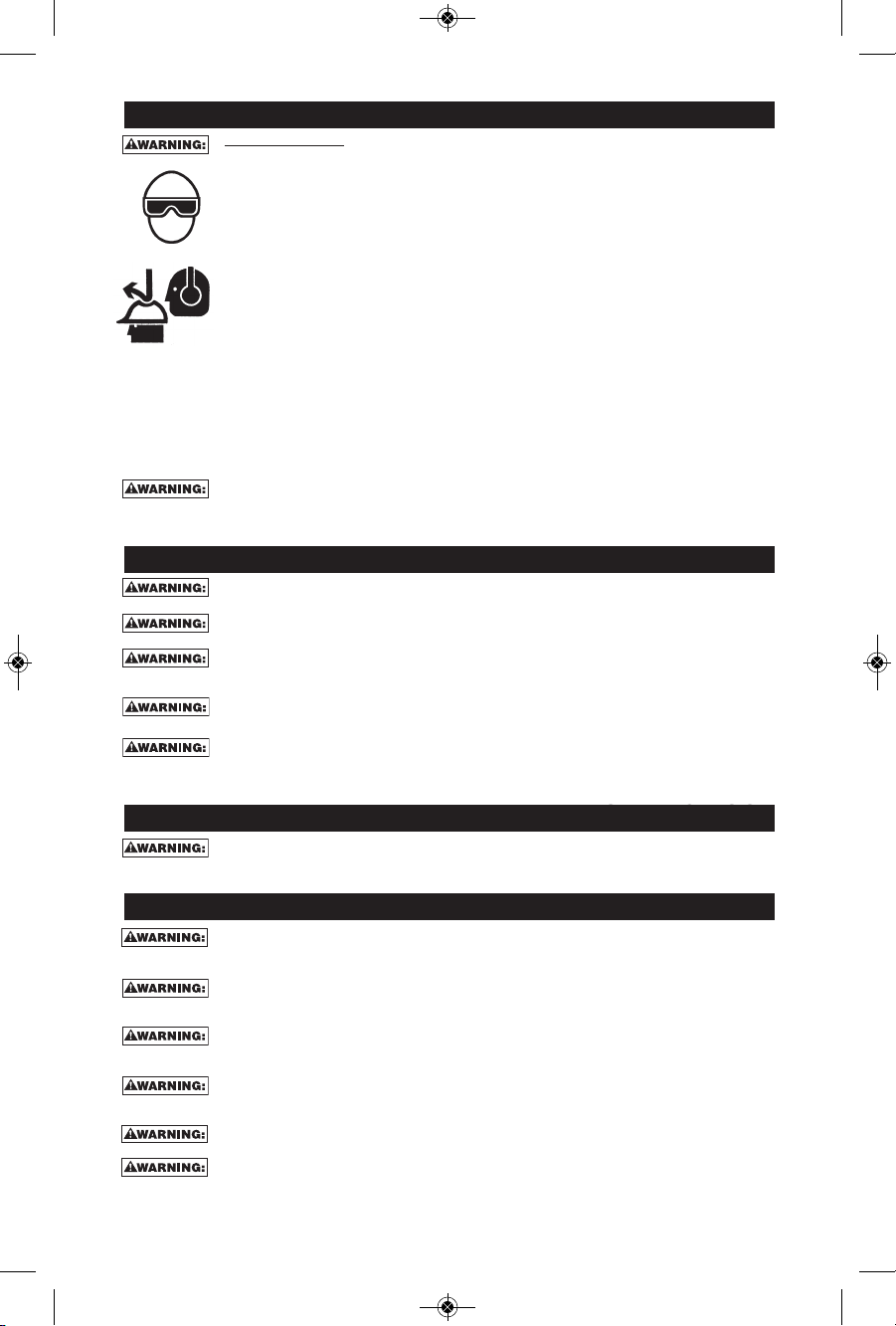
EYE PROTECTION which conforms to ANSI specifications and provides protection
against flying particles both from the FRONT and SIDE should ALWAYS be worn by the
operator and others in the work area when connecting to air supply, loading, operating
or servicing this tool. Eye protection is required to guard against flying fasteners and
debris, which could cause severe eye injury.
The employer and/or user must ensure that proper eye protection is worn. Eye
protection equipment must conform to the requirements of the American National
Standards Institute, ANSI Z87.1/CAN/CSA Z94.3 and provide both frontal and side
protection. NOTE: Non-side shielded spectacles and face shields alone do not provide
adequate protection.
Additional Safety Protection will be required in some environments. For example, the
working area may include exposure to noise level which can lead to hearing damage.
The employer and user must ensure that any necessary hearing protection is provided
and used by the operator and others in the work area. Some environments will require
the use of head protection equipment. When required, the employer and user must
ensure that head protection conforming to ANSI CAN/CSA Z89.1 is used.
Some dust created by power sanding, sawing, grinding, drilling, and other construction
activities contains chemicals known to the State of California to cause cancer, birth
defects or other reproductive harm. Some examples of these chemicals are:
• lead from lead-based paints
• crystalline silica from bricks and cement and other masonry products
• arsenic and chromium from chemically-treated lumber
Your risk from these exposures varies, depending on how often you do this type of
work. To reduce your exposure to these chemicals: work in a well ventilated area, and
work with approved safety equipment, such as those dust masks that are specially
designed to filter out microscopic particles.
AIR SUPPL AND CONNECTIONS
Do not use oxygen, combustible gases, or bottled gases as a power source for this tool as
tool may explode, possibly causing injury.
Do not use supply sources which can potentially exceed 200 P.S.I.G. as tool may burst,
possibly causing injury.
The connector on the tool must not hold pressure when air supply is disconnected. If a
wrong fitting is used, the tool can remain charged with air after disconnecting and thus will
be able to drive a fastener even after the air line is disconnected possibly causing injury.
Do not pull trigger or depress contact arm while connected to the air supply as the tool
may cycle, possibly causing injury.
Always disconnect air supply: 1.) Before making adjustments; 2.) When servicing the tool;
3.) When clearing a jam; 4.) When tool is not in use; 5.) When moving to a different work
area, as accidental actuation may occur, possibly causing injury; 6.) Before placing tool on
any surface, hanging tool on belt, or otherwise temporarily suspending use of the tool.
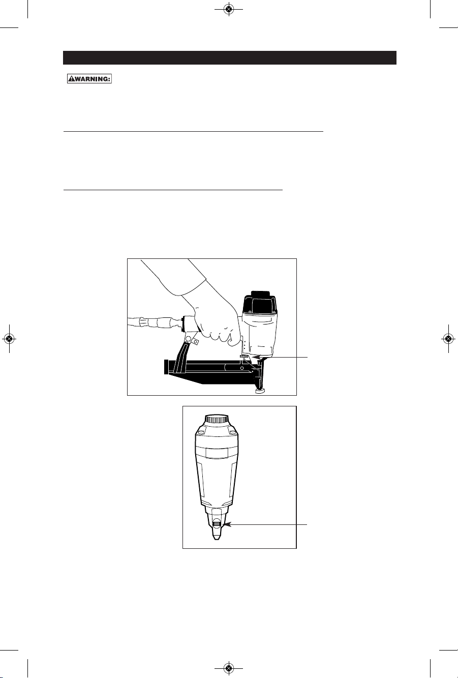
LOADING TOOL
When loading tool: 1.) Never place a hand or any part of body in fastener discharge
area of tool; 2.) Never point tool at anyone; 3.) Do not pull the trigger or depress the
trip as accidental actuation may occur, possibly causing injury.
OPERATION
Always handle the tool with care: 1.) Never engage in horseplay; 2.) Never pull the trigger
unless nose is directed toward the work; 3.) Keep others a safe distance from the tool
while tool is in operation as accidental actuation may occur, possibly causing injury.
The operator must not hold the trigger pulled on contact arm tools except during
fastening operation as serious injury could result if the trip accidentally contacted
someone or something, causing the tool to cycle.
Keep hands and body away from the discharge area of the tool. A contact arm tool may
bounce from the recoil of driving a fastener and an unwanted second fastener may be
driven possibly causing injury.
Check operation of the contact arm mechanism frequently. Do not use the tool if the
arm is not working correctly as accidental driving of a fastener may result. Do not
interfere with the proper operation of the contact arm mechanism.
Do not drive fasteners on top of other fasteners or with the tool at an overly steep angle
as this may cause deflection of fasteners which could cause injury.
Do not drive fasteners close to the edge of the work piece as the wood may split,
allowing the fastener to be deflected possibly causing injury.
AIR SUPPLY AND CONNEC IONS
OPERA ION
LOADING OOL
SAFE Y INS RUC IONS