manuals.online logo
Brands
  1. Home
  2. •
  3. Brands
  4. •
  5. Portfolio
  6. •
  7. Outdoor Light
  8. •
  9. Portfolio 00686 User manual

Portfolio 00686 User manual

PACKAGE CONTENTS/CONTENIDO DEL PAQUETE
14 PC LANDSCAPE
LIGHTING KIT
KIT DE ILUMINACIÓN PARA
EL JARDIN DE 14 PIEZAS
ITEM/ARTÍCULO #0810815
MODEL/MODELO #00686
Serial Number/Número de serie
Purchase Date/Fecha de compra
PORTFOLIO® and PORTFOLIO & Design™ are
trademarks or registered trademark of LF, LLC.
All rights reserved.
PORTFOLIO® y PORTFOLIO & Design™ son
marcas o marcas registradas de LF, LLC.
Todos los derechos reservados.
Questions?/¿Preguntas?
Call customer service at 1-800-643-0067,
8 a.m. - 6 p.m., EST, Monday - Thursday,
8 a.m. - 5 p.m., EST, Friday.
ATTACH YOUR RECEIPT HERE
ADJUNTE SU RECIBO AQUÍ
Printed in China
Impreso en China EB16110
Llame a Servicio al Cliente al 1-800-643-0067, de
lunes a jueves de 8 a.m. a 6 p.m., y los viernes de
8 a.m. a 5 p.m., hora estándar del Este.
WARRANTY/GARANTÍA
The manufacturer warrants this lighting xture against defects in materials and workmanship for a period of one year from
the date of purchase. If within this period the product is found to be defective in material or workmanship, the product must
be returned, with a copy of the bill of sale as proof of purchase, to the original place of purchase. The manufacturer will, at its
option, repair, replace or refund the purchase price to the original purchaser. This warranty does not cover light bulbs or the
xture becoming damaged due to misuse, accidental damage, improper handling and/or installation and specically excludes
liability for direct, incidental or consequential damages. As some states do not allow exclusions or limitations on an implied
warranty, the above exclusions and limitations may not apply. This warranty gives you specic rights and you may also have
other rights that vary from state to state.
El fabricante garantiza la ausencia de defectos en los materiales o en la fabricación de todos sus accesorios de iluminación
durante un período de un año a partir de la fecha de compra. Si dentro de este período el producto presenta defectos en el
material o la mano de obra, se debe devolver el producto, junto con una copia del recibo de venta como prueba de la compra,
al lugar donde se compró. El fabricante, a su elección, reparará, reemplazará o devolverá el monto de la compra al comprador
original. Esta garantía no cubre daños en el ensamble debido a mal uso, daño accidental, manipulación o instalación
inadecuada y/o excluye especícamente toda responsabilidad por daños directos, accidentales o resultantes. Debido a que
algunos estados no permiten exclusiones o limitaciones en una garantía implícita, las exclusiones y limitaciones anteriores
pueden no aplicarse. Esta garantía le otorga derechos especícos pero podría tener también otros derechos que varían según
el estado.
AC
REPLACEMENT PARTS LIST/LISTA DE PIEZAS DE REPUESTO
PART
PIEZA
DESCRIPTION
DESCRIPCIÓN
PART #
PIEZA #
ATop tier cover/Cubierta de la
parte superior 301001-0122OL
B Plastic lens/Mica plástica 990706-0066CL
C Bottom tier/Parte inferior 302001-0017OL
DFixture body/Cuerpo de la lámpara 303002-0074BK
F Plastic tier stake/Estaca de plástico 303003-0048BK
I Lens/ Mica 990706-0067CL
J Socket/Portalámpara 990323-0066CL
KFixture housing/Carcasa del ensamble 301001-0123OL
LPlastic pivot stake
Estaca giratoria de plástico 303003-0043BK
For replacement parts, call our customer service department at 1-800-643-0067./Para obtener piezas de repuesto, llame a
nuestro Departamento de Servicio a 1-800-643-0067.
B
x 10
Top tier cover
Cubierta de la parte
superior
1
8
x 10
Plastic lens
Mica plástica
x 10
Bottom tier
Parte inferior
A
DF
E
x 10
Connector
Conector
x 10
Fixture body
Cuerpo de la
lámpara
x 10
Plastic tier stake
Estaca de plástico
GH
x 1
Transformer
Transformador
x 1
Low-voltage cable
Estaca de plástico
I
J
K
L
x 2
Lens (preassembled
to xture housing (K))
Mica (preensamblada
en la lámpara (K)) x 2
Socket
(preassembled to lens (I))
Portalámpara
(preensamblada en mica (I))
x 2
Fixture housing
Carcasa del ensamble
x 2
Plastic pivot stake
Estaca giratoria de plástico
A
B
C
D
I
J
F
K
L
x 12
Bulb
Bombilla
M
ETL MODEL #688428
SAFETY INFORMATION/INFORMACIÓN DE SEGURIDAD
Before beginning assembly of product, make sure all parts are present. Compare parts with package contents list and hardware
contents list. If any part is missing or damaged, do not attempt to assemble the product.
Estimated Assembly Time: 90 minutes
Tools required for assembly (not included): Screwdriver, 5/16 drill bit and drill.
Antes de comenzar a ensamblar el producto, asegúrese de tener todas las piezas. Compare las piezas con la lista del
contenido del paquete y los aditamentos mencionados anteriormente. No intente ensamblar, instalar o usar el producto si falta
alguna pieza o si las piezas están dañadas.
Tiempo estimado de ensamblaje: 90 minutos
Herramientas necesitan para el ensamblaje (no se incluyen): Deatornillador, 5/16 broca, perforar.
WARNING/ADVERTENCIA
PREPARATION/PREPARACIÓN
CAUTION/PRECAUCIÓN
• For use with low-voltage landscape lighting systems only.
Para usar únicamente con sistemas de iluminación para el jardín de bajo voltaje.
• To reduce the risk of re or injury, turn off/unplug and allow to cool before replacing bulb.
Para reducir el riesgo de incendio o lesiones, apague o desenchufe y deje que la bombilla se enfríe antes de reemplazarla.
• DO NOT operate or install a xture with missing or damaged parts.
NO haga funcionar ni instale una lámpara si falta alguna pieza o si estas están dañadas.
• Keep lamp away from materials that may burn.
Mantenga la bombilla alejada de materiales que puedan prenderse.
• Install all luminaires 10 ft. or more from a pool, spa or fountain.
Instale todas las luminarias al menos a 3,05 m de piscinas, spas o fuentes de agua.
• This transformer is for use with low-voltage landscape lighting systems ONLY.
Este transformador se debe usar ÚNICAMENTE con sistemas de iluminación para el jardín de bajo voltaje.
• This transformer is suitable for outdoor use ONLY. Do not mount power pack inside homes, garages, basements or any
enclosed structures.
Este transformador se debe usar ÚNICAMENTE en exteriores. No monte el bloque de alimentación en el interior de
hogares, garajes, sótanos ni en cualquier estructura cerrada.
• Do not install or connect wires with wet hands.
No instale ni conecte los cables con las manos mojadas.
• The low-voltage cable is intended for shallow burial - maximum depth must not exceed 6 in..
El cable de bifurcación está diseñado para uso subterráneo a poca profundidad; la profundidad máxima no debe superar los
15,24 cm (6 pulg).
• Do not step on or drive over the low-voltage cable or power cable.
No marche sobre ni pase su vehículo sobre el cable de bifurcación ni sobre el cable de alimentación.
• ONLY plug the transformer cord into a covered 120-volt Class A Type GFCI (ground fault circuit interrupter) receptacle with
a hooded ush type cover plate marked “WET LOCATION.”
SOLO enchufe el cable del transformador en un interruptor de circuito de falla de puesta a tierra (GFCI, por sus siglas en
inglés) Clase A de 120 voltios con una placa de cubierta tipo capuchón al ras con la inscripción “PARA LUGARES
HÚMEDOS”.
• Always disconnect the transformer from the electrical outlet when working on the lighting system.
Siempre desconecte el transformador del tomacorriente cuando realice trabajos en el sistema de iluminación.
• The device is a certied component of a landscape lighting systems in which the suitability of the combination shall be
determined by UL or other inspection authorities having jurisdiction.
El dispositivo es un componente certicado del sistema de iluminación para el jardín donde la aptitud de la combinación será
determinada por UL o por otras autoridades de inspección que tengan jurisdicción.
Please read and understand this entire manual before attempting to assemble, operate or install the product.
Lea y comprenda completamente este manual antes de intentar ensamblar, usar o instalar el producto.
23
CALCULATING LIGHTING CAPACITY/CÁLCULO DE LA CAPACIDAD DE ILUMINACIÓN
• The transformer has an 88-watt circuit. To determine the maximum number of xtures that can be safely connected to this
transformer, add the individual wattages of each xture. The total wattage of your xtures must not exceed 88 watts.
El transformador tiene un circuito de 88 vatios. Para determinar el número máximo de lámparas que se pueden conectar de
forma segura a este transformador, sume los vatajes individuales de cada lámpara. El vataje total de las lámparas no debe
exceder los 88 vatios.
Note: Hardware shown actual size./Nota: Los aditamentos se muestran en tamaño real.
BB
x 1
Anchor
Ancla
x 1
Screw
Tornillo
HARDWARE CONTENTS/QUINCAILLERIE INCLUSE
AA
NOTE: This equipment has been tested and found to comply with the limits for a Class B digital device, pursuant to Part 15
of the FCC Rules. These limits are designed to provide reasonable protection against harmful interference in a residential
installation. This equipment generates uses and can radiate radio frequency energy and, if not installed and used in accordance
with the instructions, may cause harmful interference to radio communications. However, there is no guarantee that interference
will not occur in a particular installation. If this equipment does cause harmful interference to radio or television reception, which
can be determined by turning the equipment off and on, the user is encouraged to try to correct the interference by one or more
of the following measures: Reorient or relocate the receiving antenna. Increase the separation between the equipment and
receiver. Connect the equipment into an outlet on a circuit different from that to which the receiver is connected. Consult the
dealer or an experienced radio/TV technician for help.
NOTA: Este equipo ha sido probado y se ha vericado que cumple con los límites para un dispositivo digital clase B, conforme
a la sección 15 de las reglas de la FCC. Estos límites se han diseñado para proporcionar una protección razonable contra la
interferencia perjudicial en una instalación residencial. Este equipo genera, utiliza y puede irradiar energía de radiofrecuencia
y, si no se instala y se usa de acuerdo con las instrucciones, puede causar interferencia perjudicial a las comunicaciones de
radio. Sin embargo, no se garantiza que no se producirán interferencias en una instalación en especial. Si este equipo genera
una interferencia perjudicial para la recepción de radio o televisión, que se puede determinar apagando y encendiendo el
equipo, se recomienda al usuario que intente corregir la interferencia con una o más de las siguientes medidas:Reoriente o
reubique la antena de recepción. Aumente la separación entre el equipo y el receptor. Conecte el equipo a un tomacorriente de
un circuito distinto al que usa el receptor. Solicite ayuda al concesionario o a un técnico con experiencia en radio/TV.
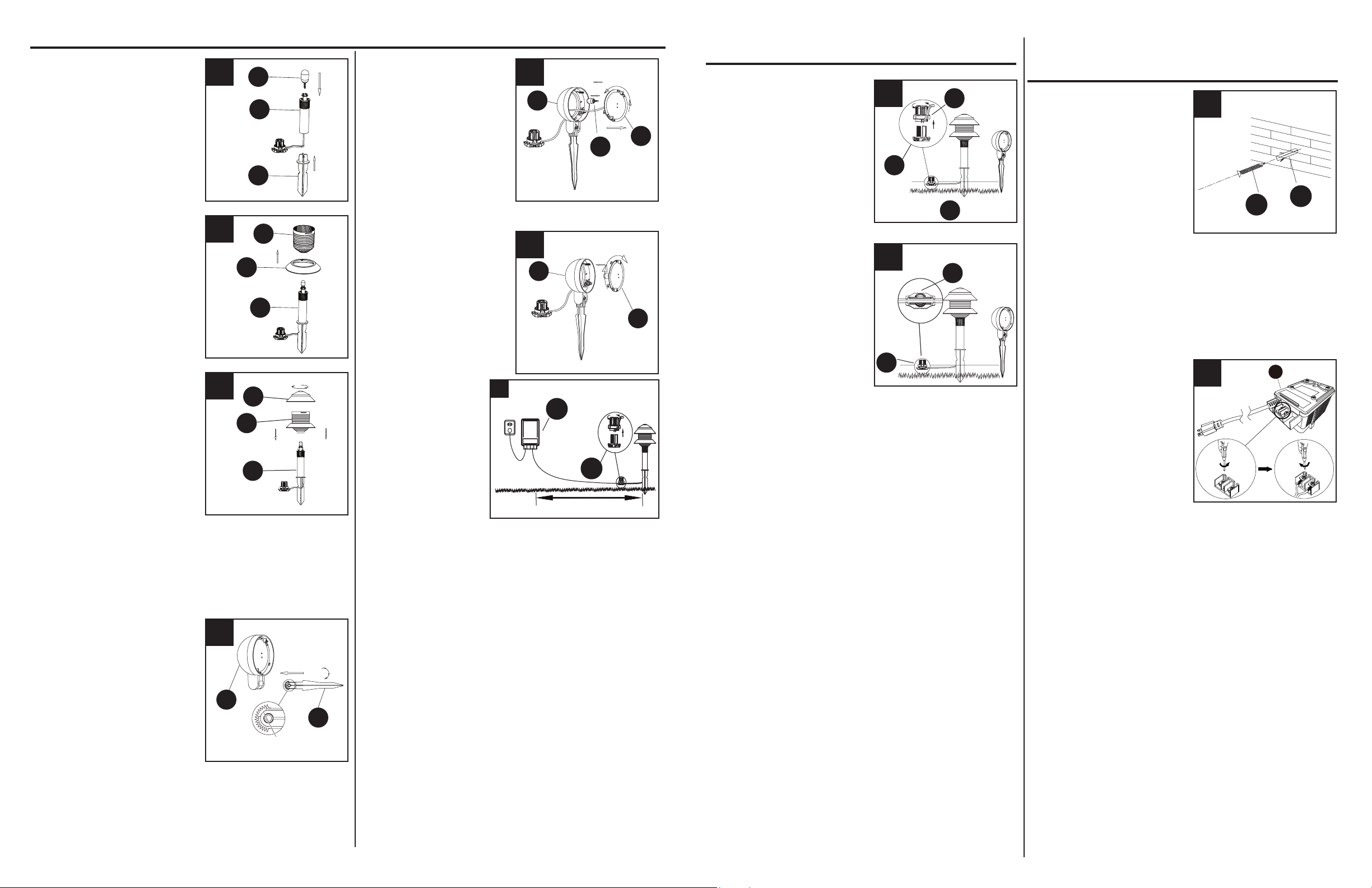
1. Select location near an
outdoor GFCI outlet with a
cover plate marked WET
LOCATION. Drill hole
using a 5/16 in. drill bit
(not included). Install an
anchor (AA) and screw
(BB), leaving enough space
for the keyhole slots on the
back of the transformer (H)
to hang on.
8. Disassemble the connectors
(E) by unscrewing the con-
nector top covers (E1) from
the wire guide (E2).
Desensamble el conector
(E) desatornillando la cubi-
erta superior del conector
(E1) de la guía para cables
(E2).
9. Insert low-voltage cable
(G) from transformer (H)
into the wire guides (E2)
by twisting the low-voltage
cable (G) into each end of
the wire guides (E2). Ensure
low-voltage cable (G) lays
at and straight in the wire
guides (E2). Align the pins
on the connector top cover
(E1) so each pin lines up
A
D
B
B
C
D
C
ASSEMBLY INSTRUCTIONS
INSTRUCCIONES DE ENSAMBLAJE
45
ASSEMBLY INSTRUCTIONS/INSTRUCCIONES DE ENSAMBLAJE
5. Unscrew the lens (I) from
the xture housing (K) by
turning it counterclockwise.
Insert the bulb (M) into the
lens (I).
Desenrosque la mica (I)
de la carcasa de la luz
direccional (K), girándola
en dirección contraria a las
manecillas del reloj. Inserte
la bombilla (M) en la mica (I).
6. Reattach the lens (I) to the
xture housing (K).
Repeat steps 4 - 6 for the
remaining spotlight.
Vuelva a colocar la mica
(I) en la carcasa de la
lámpara (K).
Repita los pasos 4 a 6
parael centro de atención
restantes.
2
1
3
TRANSFORMER ASSEMBLY INSTRUCTIONS
BLOQUE DE ALINENTACIO INSTRUCTIONS
POUR L’ASSEMBLAGE
10 ft. / 3,04 m
7
E
H
1. Insert the bulb (M) into the
xture body (D) and attach
the xture body (D) to the
plastic tier stake (F).
Inserte la bombilla (M) al
cuerpo de la lámpara (D) y
je el cuerpo de la lámpara
(D) a la estaca de plástico
(F).
2. Attach the bottom tier (C)
to the plastic lens (B) by
twisting it clockwise until
secure.
Fije la sección inferior (C) a
la mica de plástico (B). Para
ello, gírela en dirección de
las manecillas del reloj hasta
que esté segura.
3. Attach the plastic lens (B)
to the xture body (D).
Then attach the top tier
cover (A) to the plastic lens
(B) assembly by twisting it
clockwise until secure.
Repeat steps 1-3 for the
remaining 9 path lights.
M
D
F
3
Fije la mica de plástico (B) al cuerpo de la lámpara
(D). Luego, je la cubierta de la sección superior (A) al
ensamble de la mica de plástico (B). Para ello, gírela en
dirección de las manecillas del reloj hasta que esté segura.
Repita los pasos 1 a 3 para instalar las 9 luces para
senderos restantes.
K
L
gap
separación
4
4. To attach the plastic pivot
stake (L) to the xture
housing (K), align the gap on
the plastic pivot stake (L) with
the slot in the xture housing
(K) and rotate the stake
downward until it is secure.
Para jar la estaca giratoria
deplástico (L) a la carcasa de
la lámpara (K), alinee la separación de la estaca giratoria
de plástico (L) con la ranura de la carcasa de la lámpara
(K) y gire la estaca hacia abajo hasta que esté segura.
5
I
M
K
6
I
K
7. Lay low-voltage
cable (G) in the
general area where
the lights are to be
installed. Distribute
the light xtures as
evenly as possible
along the low-voltage
cable (G).
NOTE: The rst xture should be a minimum of 10 ft. away
from where transformer (H) will be installed. Once desired
installation spots for each xture is determined, push xtures
into the ground.
CAUTION: When installing the xture into the ground, do
NOT push on the xture head. Instead, hold the body of the
xture and push the xture into the ground. For ground with
hard soil, use a trowel (not included) to loosen the soil. DO
NOT use a hammer to install this xture.
Coloque el cable de bajo voltaje (G) en el área general
donde se instalarán las luces. Distribuya los ensambles de
luz lo más parejo que pueda a lo largo del cable de bajo
voltaje (G).
NOTA: La primera lámpara debe estar a una distancia
mínima de 3,04 m (10 pies) de donde se instalará el
transformador (H). Una vez que se hayan determinado los
puntos de instalación deseados para cada lámpara, clave
las lámparas en el suelo.
PRECAUCIÓN: NO ejerza presión sobre el cabezal de la
lámpara cuando instale la lámpara en el suelo. En lugar
de ello, sostenga el poste y clave la lámpara en el suelo.
Para suelos con tierra dura, use pala de jardinería llana (no
se incluye) para aojar la tierra. NO utilice un martillo para
instalar esta lámpara.
8
E
E2
E1
9
E
E
E2
with opposite sides of the low-voltage cable (G). Securely
tighten the connector top cover (E1), making sure the
pins completely pierce the plastic shield of the low-voltage
cable (G).
Inserte el cable de bajo voltaje (G) del transformador (H)
en las guías para cables (E2). Para ello, gire el cable de
bajo voltaje (G) en cada extremo de las guías para cables
(E2).Asegúrese de que el cable de bajo voltaje (G) quede
plano y recto en la guía para cables (E2). Alinee las clavi-
jas en la cubierta superior del conector (E1), de manera
que cada clavija se alinee con los extremos opuestos del
cable de bajo voltaje (G). Apriete bien la cubierta superior
del conector (E1) asegurándose de que las clavijas atra-
viesen por completo la protección de plástico del cable de
bajo voltaje (G).
Elija una ubicación cerca de un tomacorriente eléctrico
de GFCI en exteriores con una placa de cubierta con
la inscripción “PARA LUGAR HÚMEDO”. Taladre un
oricio piloto con una broca para taladro de 5/16” (no se
incluye). Instale un ancla de expansión (AA) y un tornillo
(BB) y deje suciente espacio para que las ranuras con
forma de cerradura del transformador (H) cuelguen.
1
AA
BB
2H
2. Loosen the terminal screws
on the bottom of the
transformer (H) and insert
one of the pre-stripped
wires under the terminal
clamping plate and securely
tighten the terminal screw.
Repeat this process for
the other side of the wire,
inserting it into the second
wire terminal.
Suelte los tornillos del terminal ubicados en la parte
inferior del transformador (H) e inserte uno de los cables
pelados previamente debajo de la placa de sujeción
del terminal y apriete rmemente el tornillo del terminal.
Repita este proceso para el otro lado del cable e
insértelo en el segundo terminal del cable.
PRECAUCIÓN: Para reducir el riesgo de incendio,
descarga eléctrica o daño al transformador (H),
asegúrese de que no haya aislamiento de cable debajo
de la placa de sujeción del terminal y que los tornillos
que conectan el cable a los terminales del transformador
estén fuertemente apretados.
CAUTION: To reduce the risk of re, electrical shock or
damage to the transformer (H), ensure there is no wire
insulation under the terminal clamping plate and the
screws connecting the cable to the transformer terminals
are securely tightened.
1. Set the transformer (H) timer adjustment knob to your desired setting.
Coloque la perilla de ajuste del temporizador del transformador (H) en la
conguración deseada.
OFF: Turns the transformer (H) off./OFF (Apagado): Apaga el transformador (H).
ON: Turns the transformer (H) on./ON (Encendido): Enciende el transformador (H).
AUTO: When sunlight more than 10 LUX (morning light) contacts the photoeye,
the transformer (H) will go into standby mode. When sunlight is less than 10 LUX
(evening light) the photoeye will activate the transformer (H).
AUTO (AUTOMÁTICO): Cuando la luz del sol de más de 10 LUX (luz matinal) el
transformador (H) entrará en modo de espera. Cuando la luz del sol sea inferior a
10 LUX (luz nocturna), el sensor fotoeléctrico activará el transformador (H).
8H: When sunlight is less than 10 LUX (evening light) the photoeye will activate the transformer (H) for eight hours.
8H: Cuando la luz del sol sea inferior a 10 LUX (luz nocturna), el sensor fotoeléctrico activará el transformador (H) durante
ocho horas.
6H: When sunlight is less than 10 LUX (evening light) the photoeye will activate the transformer (H) for six hours.
6H: Cuando la luz del sol sea inferior a 10 LUX (luz nocturna), el sensor fotoeléctrico activará el transformador (H) durante
seis horas.
4H: When sunlight is less than 10 LUX (evening light) the photoeye will activate the transformer (H) for four hours.
4H: Cuando la luz del sol sea inferior a 10 LUX (luz nocturna), el sensor fotoeléctrico activará el transformador (H) durante
cuatro horas.
2. Place the transformer (H) in an area free from plants or other obstructions that will
prevent sunlight from coming into contact with it. The photoeye should not be
located where street lights, exterior lights or other light sources may shine directly
upon it. Note: The transformer (H) and photoeye do not operate when the switch
is in the off position.
Coloque el transformador (H) en un área donde no haya plantas ni otras
obstrucciones que impidan que reciba la luz del sol. El sensor fotoeléctrico no
debe estar ubicado en un lugar donde las luces de la calle, las luces exteriores u
otras fuentes de luz puedan caer directamente sobre él. Nota: Tenga en cuenta
que el transformador (H) y el sensor fotoeléctrico no funcionan cuando el
interruptor está en la posición de apagado (off).
3. If a short circuit occurs this may activate the internal circuit breaker on the
transformer (H). Press the circuit breaker reset button to reset the transformer (H).
Si se produce un cortocircuito, este puede activar el interruptor de circuito interno
del transformador (H). Presione el botón de reinicio del interruptor del circuito
para reiniciar el transformador (H).
OPERATING INSTRUCTIONS/INSTRUCCIONES DE FUNCIONAMIENTO
CARE AND MAINTENANCE/
CUIDADO Y MANTENIMIENTO
67
1
C
I
H
H
Circuit breaker
Cortacircuitos
3
H
• Before attempting to clean the xture, disconnect the power to the xture by turning the breaker off and removing the fuse
from the fuse box.
Antes de intentar limpiar la lámpara, desconecte la alimentación de la lámpara apagando el interruptor de circuito o retirando
el fusible de la caja de fusibles.
• To clean the xture, use a dry or slightly dampened clean cloth.
Para limpiar la lámpara, use un paño limpio seco o levemente húmedo.
• DO NOT use any cleaners with chemicals, solvents or harsh abrasives as damage to the xture may occur.
NO utilice limpiadores con químicos, solventes ni abrasivos fuertes ya que pueden dañar la lámpara.
• Bulb Replacement: Use 4-watt, 12-volt wedge-base incandescent bulbs or compatible LEDs; CFLs are not recommended
for this item.
Reemplazo de la bombilla: Use bombillas incandescente con base en forma de cuña de 4 vatios y 12 voltios o bombillas
LED compatibles; no se recomienda el uso de bombillas CFL.
• DO NOT touch new bulb with bare hands as oil from skin may damage the lamp and cause short bulb life.
NO toque la bombilla nueva con las manos descubiertas, ya que el aceite de la piel puede dañar la lámpara y acortar la vida
útil de la bombilla.
TROUBLESHOOTING/
SOLUCIÓN DE PROBLEMAS
PROBLEM
PROBLEMA
POSSIBLE CAUSE
CAUSA POSIBLE
CORRECTIVE ACTION
ACCIÓN CORRECTIVA
The light does not turn
on at night.
La luz no se enciende
al anochecer.
1. The transformer is not plugged in or turned
on.
El transformador no está enchufado o
encendido.
2. The bulb is broken.
La bombilla está rota.
3. Fixture connector is not properly installed on
the low-voltage cable.
El conector de la lámpara no está instalado
correctamente en el cable de bajo voltaje.
1. Make sure the transformer is plugged in
and turned on.
Asegúrese de que el transformador esté
enchufado y encendido.
2. Replace with new bulb.
Remplace la bombilla por una nueva.
3. Make sure the contact pins pierce the wire
insulation and make proper contact with
the wire.
Asegúrese de que las clavijas de contacto
atraviesen el aislamiento del cable y estén
en contacto con el cable de forma
adecuada.
2
IH
Photoeye
Fotosensor

This manual suits for next models

1

Other Portfolio Outdoor Light manuals

Portfolio 00906 User manual

Portfolio

Portfolio 00906 User manual

Portfolio P1015B User manual

Portfolio

Portfolio P1015B User manual

Portfolio 00907 User manual

Portfolio

Portfolio 00907 User manual

Portfolio FY09-010 User manual

Portfolio

Portfolio FY09-010 User manual

Portfolio FY09-002 User manual

Portfolio

Portfolio FY09-002 User manual

Portfolio IAN1501L-4 User manual

Portfolio

Portfolio IAN1501L-4 User manual

Portfolio 0338648 User manual

Portfolio

Portfolio 0338648 User manual

Portfolio 00751 User manual

Portfolio

Portfolio 00751 User manual

Portfolio LW688488 User manual

Portfolio

Portfolio LW688488 User manual

Portfolio 00768 User manual

Portfolio

Portfolio 00768 User manual

Portfolio Barada LBSH02MTN User manual

Portfolio

Portfolio Barada LBSH02MTN User manual

Portfolio 00744 User manual

Portfolio

Portfolio 00744 User manual

Portfolio SL8P-N2-BK-D2 User manual

Portfolio

Portfolio SL8P-N2-BK-D2 User manual

Portfolio WLL131SB User manual

Portfolio

Portfolio WLL131SB User manual

Portfolio WL126WW User manual

Portfolio

Portfolio WL126WW User manual

Portfolio EL0529BK-6 User manual

Portfolio

Portfolio EL0529BK-6 User manual

Portfolio B10065 User manual

Portfolio

Portfolio B10065 User manual

Portfolio SS39P-P3-BK-C1 User manual

Portfolio

Portfolio SS39P-P3-BK-C1 User manual

Portfolio 00976 User manual

Portfolio

Portfolio 00976 User manual

Portfolio PL127MBK User manual

Portfolio

Portfolio PL127MBK User manual

Portfolio RS40Pb-R8-RS-C4 User manual

Portfolio

Portfolio RS40Pb-R8-RS-C4 User manual

Portfolio 4193 User manual

Portfolio

Portfolio 4193 User manual

Portfolio LWS0038D User manual

Portfolio

Portfolio LWS0038D User manual

Portfolio 00756 User manual

Portfolio

Portfolio 00756 User manual

Popular Outdoor Light manuals by other brands

Würth WLH 1 Premium Translation of the original operating instructions

Würth

Würth WLH 1 Premium Translation of the original operating instructions

MOOD CHIC instruction manual

MOOD

MOOD CHIC instruction manual

LUG TRAFFIK LED Installation instruction

LUG

LUG TRAFFIK LED Installation instruction

LIGMAN BENTON 2 installation manual

LIGMAN

LIGMAN BENTON 2 installation manual

HEPER TURA 2x16 LED Installation & maintenance instructions

HEPER

HEPER TURA 2x16 LED Installation & maintenance instructions

Clas Ohlson LS7H01-UK instruction manual

Clas Ohlson

Clas Ohlson LS7H01-UK instruction manual

LIGMAN DUOMO 12 installation manual

LIGMAN

LIGMAN DUOMO 12 installation manual

BenQ AR15 D Genie user manual

BenQ

BenQ AR15 D Genie user manual

Garden Lights FOCUS Plus SMART 3200011 user manual

Garden Lights

Garden Lights FOCUS Plus SMART 3200011 user manual

Dayvia Wellbi Instructions for use

Dayvia

Dayvia Wellbi Instructions for use

John Lewis DOME TABLE LAMP user guide

John Lewis

John Lewis DOME TABLE LAMP user guide

LIGMAN AR-20992-LC installation manual

LIGMAN

LIGMAN AR-20992-LC installation manual

LIGMAN VA-20122 installation manual

LIGMAN

LIGMAN VA-20122 installation manual

HUDSON VALLEY LIGHTING TROY LIGHTING SANDERS P2745 manual

HUDSON VALLEY LIGHTING

HUDSON VALLEY LIGHTING TROY LIGHTING SANDERS P2745 manual

LUXO Circus LED user manual

LUXO

LUXO Circus LED user manual

LIGMAN ZE-50029-30 installation manual

LIGMAN

LIGMAN ZE-50029-30 installation manual

Sygonix 2574833 operating instructions

Sygonix

Sygonix 2574833 operating instructions

Maxim Lighting 12163CHB manual

Maxim Lighting

Maxim Lighting 12163CHB manual

manuals.online logo
manuals.online logoBrands
  • About & Mission
  • Contact us
  • Privacy Policy
  • Terms and Conditions

Copyright 2025 Manuals.Online. All Rights Reserved.