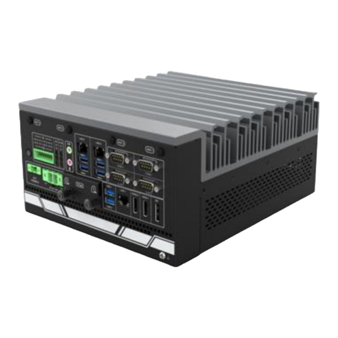
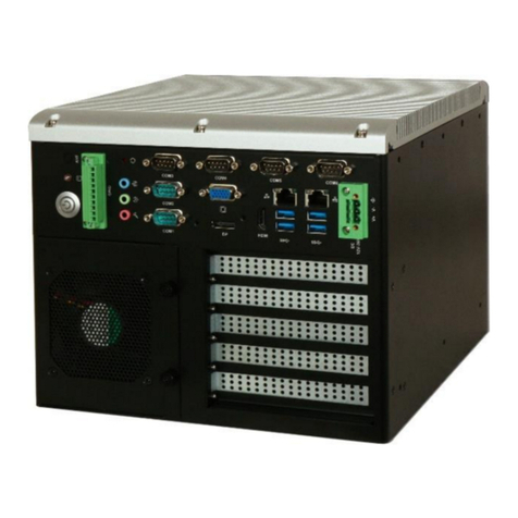
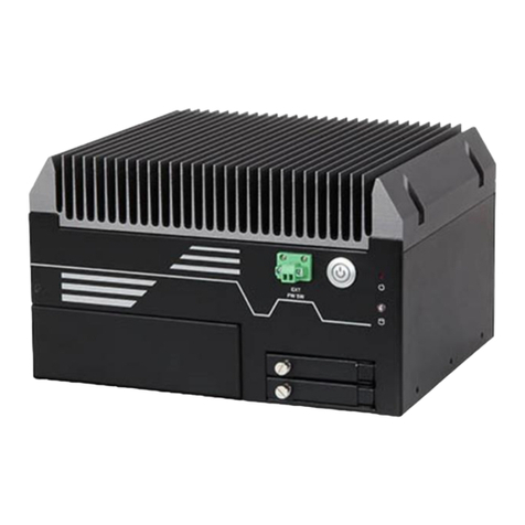
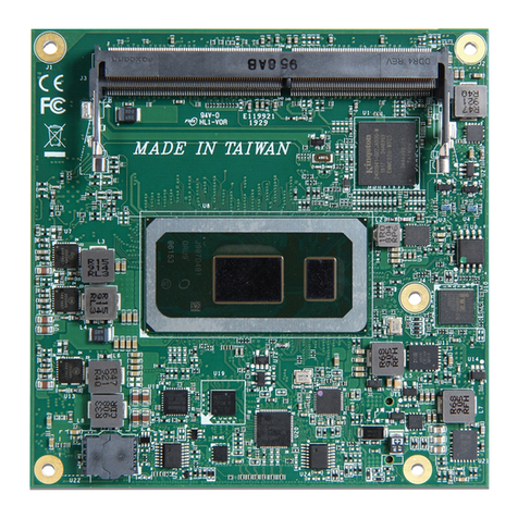
Portwell WEBS-45H1 User manual

WEBS-45H1
Fan-less Embedded System
AS5-3627
User's Manual
Version 1.2
Copyright © Portwell, Inc., 2022. All rights reserved.
All other brand names are registered trademarks of their respective owners.

Preface
Table of Contents
How to Use This Manual
Chapter 1 System Overview.......................................................................................................1-1
1.1 Introduction.................................................................................................................................. 1-1
1.2 Check List ..................................................................................................................................... 1-1
1.3 Product Specification .................................................................................................................. 1-2
1.4 Mechanical Dimension................................................................................................................ 1-3
Chapter 2 System Installation....................................................................................................2-1
2.1 Embedded Board H/W Jumper Setting Introduction ............................................................ 2-1
2.1.1 M/B Block overview ......................................................................................................... 2-1
2.1.2 M/B Jumper setting .......................................................................................................... 2-2
2.2 CPU and Memory module Installation .................................................................................. 2-11
2.3 2.5” SDD Installation................................................................................................................. 2-13
2.4 I/O Interfaces ............................................................................................................................. 2-15
2.4.1 Front View ........................................................................................................................ 2-15
2.4.2 Rear View ......................................................................................................................... 2-16
2.5 Getting Started ........................................................................................................................... 2-17
Chapter 3 BIOS Setup Information..........................................................................................3-18
3.1 Entering Setup.............................................................................................................................. 3-18
3.2 Main............................................................................................................................................. 3-19
3.2.1 Main.......................................................................................................................................... 3-19
3.3 Configuration ............................................................................................................................. 3-21
3.4 Security ....................................................................................................................................... 3-36
3.5 Boot.............................................................................................................................................. 3-38
3.6 Save & Exit.................................................................................................................................. 3-39
3.7 Troubleshooting......................................................................................................................... 3-40
Chapter 4 Important Instructions ..............................................................................................4-1
4.1 Note on the Warranty ................................................................................................................. 4-1
4.2 Exclusion of Accident Liability Obligation .............................................................................. 4-1
4.3 Liability Limitations / Exemption from the Warranty Obligation....................................... 4-1
4.4 Declaration of Conformity.......................................................................................................... 4-1
Chapter 5 Frequent Asked Questions.......................................................................................5-2
Preface
How to Use This Manual
The manual describes how to configure your WEBS-45H1 system to meet various operating requirements. It
is divided into four chapters, with each chapter addressing a basic concept and operation of Fan-less Embedded
System.
Chapter 1: System Overview. Present what you have in the box and give you an overview of the product
specifications and basic system architecture for this fan-less embedded system.
Chapter 2: System Installation. Show the definitions and locations of all the interfaces and describe a proper
installation guide so that you can easily configure your system.
Chapter 3: BIOS Setup Information. Specify the meaning of each setup parameters, how to get advanced
BIOS performance and update new BIOS. In addition, POST checkpoint list will give users some guidelines of
troubleshooting.
Chapter 4: Important Instructions. Indicate some instructions which must be carefully followed when the
fan-less embedded system is used.
Chapter 5: Frequent asked questions. Provide the answers for the most frequently asked questions.
The content of this manual is subject to change without prior notice. These changes will be incorporated in new
editions of the document. The vendor may make supplement or change in the products described in this document
at any time.
Revision History
Revision
Date
Details of Change(s)
V1.0
2022/05/27
Initial Release
V1.1
2022/10/13
Updated Operation temperature condition in product specification
V1.2
2022/10/13
Update system dimension

System Overview
WEB-45H1 User’s Manual 1-1
Chapter 1 System Overview
1.1 Introduction
Portwell announces WEBS-45H1, a high-performance fan-less Box PC. The WEBS-45H1 builds on Intel®
Q470E chipset and takes advantages of 10th Generation Intel® Core™i3/i5/i7/i9 processors technologies that can
support dual DDR4 memory and 2x 2.5”SSD for storage. the WEBS-45H1 system supports high-resolution
triple-display output, serving as an ideal platform for performance and graphics-demanding applications.
Portwell's WEBS-45H1 is designed to be power-optimized and value-optimized. WEBS-45H1 utilizes a
35W Intel Embedded CPU and Intel Q470E chipset, which is more economical compared to its mobile
counterpart and provides great efficacy as well as low power consumption. The system further takes advantage of
the 10th generation Intel Core processor technologies supporting dual-channel DDR4 memory up to 64GB.
Furthermore, the WEBS-45H1 Box PC includes rich I/O interfaces and fast connectivity with three
independent display (DisplayPort/HDMI/VGA) interfaces with resolution up to 4K, two Gigabit Ethernet ports,
two RS-232/422/485 ports, three RS-232 ports, four USB 2.0 and four USB 3.2 Gen1 ports, one 8 bits GPIO port,
and Mic-in/ Line-out. Optional wireless, 4G /5G can be added via a M.2 E key socket and LTE modules can be
added via a M.2 B key socket.
The rugged, fan-less design makes the WEBS-45H1 durable in harsh environment applications, such as
factory automation and industrial automation. Portwell’s WEBS-45H1 has already passed a vibration test of
1Grms/ 10~500Hz and a shock test of 50G, assuring its solidity and reliability.
In addition, the system accepts a wide input voltage range from DC 12V to 36V. This power-source
flexibility enables product usage in a variety of situations. Moreover, the WEBS-45H1 is more than a robust and
dependable embedded system with high performance and graphics efficacy, its stylish mechanical design
enhances the system’s artistry. Potential applications include kiosk, intelligent digital security, factory automation
and surveillance applications, and many more.
1.2 Check List
The WEBS-45H1 package should cover the following basic items:
✓One WEBS-45H1 Fan-less Embedded System
✓One Wall Mount Kit
✓Other Accessories
If any of these items is damaged or missing, please contact your vendor and keep all packing materials for
future replacement and maintenance.

System Overview
WEB-45H1 User’s Manual 1-2
1.3 Product Specification
System
M/B
WADE-8212
System Chipset
Intel®Q470E chipset
CPU
10th Gen Intel® Core ™Processors CPU in LGA1200 package (35W TDP)
BIOS
AMI uEFI BIOS (SPI ROM)
System Memory
Up to 64GB DDR4 2400/2666 Non-ECC SDRAM on two SO-DIMM sockets
Storage
2x 2.5”SSD Slots
Watchdog Timer
Programmable by embedded controller
H/W Status Monitor
System monitor (Voltage, Temperature)
Expansion
1x M.2 E Key2230 with PCIe x1, CNVI and USB2.0 for Wireless
1x M.2 M Key 2242/2260/2280 with PCIe x4 and SATA3 for SSD
1x M.2 B Key 3042/3052 with USB 3.0 Signal
1x SIM Card socket
External I/O
Series Ports
5 x COM ports (2 x RS- 232/422/485)
Display
1x HDMI 2.0a, resolution up to 4096x2160 @60Hz
1x DisplayPort 1.2, resolution up to 4096x2160 @60Hz
1x VGA, resolution up to 1920x1200 @60Hz
USB
4x USB 3.2 Gen 1, 4x USB 2.0
Audio
Audio Jack with Line-out / Mic-in with Realtek ALC887 Audio controller
LAN
Intel® I219LM and Intel® I225LM Ethernet controller ,2x RJ45 connectors
GPIO
1x Programmable 8-bit Digital I/O
Other
2x Antenna hole for Wi-Fi or 4G/GPS module
- 1x EXT Power Switch
Power Supply Unit
Power Supply
DC 12~36V with 3-pin terminal block connector
Environment
Operating Temperature
-20°C ~ 40°C with Adapter
-20°C ~ 60°C with DC Source
Storage Temperature
-40°C ~ 80°C
Relative Humidity
40°C, 95%RH non-condensing
Operating Vibration
1Grms/10-500Hz, IEC 60068-2-6
Operating Shock
50G, 11 msec, IEC 60068-2-27
Mechanical
Dimension (W x D x H)
253 (W) * 201.2 (D) *111.8 (H) mm
Weight
5.5 Kg
Mounting
Wall mounting

System Overview
WEB-45H1 User’s Manual 1-3
1.4 Mechanical Dimension
Front view of the WEBS-45H1 system
Rear view of the WEBS-45H1 system
Top view of the WEBS-45H1 system

System Installation
WEB-45H1 User’s Manual 2-1
Chapter 2 System Installation
This chapter provides you with instructions to set up your system. Definitions and locations of all the
interfaces are described so that you can easily configure your system. For more detailed PIN assignment and
jumper setting, please refer to user’s manual of WADE-8212.
2.1 Embedded Board H/W Jumper Setting Introduction
2.1.1 M/B Block overview

System Installation
WEB-45H1 User’s Manual 2-2
2.1.2 M/B Jumper setting
Jumper Function List
No
Description
1
COM Port PWR Setting Jumpers (COM 1~2)
2
4-Pin ATX Power Input/Output Connector
3
24-Pin ATX Power Input Connector
4
SATA Power Output Connector
5
SATA Connector (SATA3_1~4)
6
USB 2.0 Headers
7
USB 3.2(Gen1) Headers (USB3_3_4)
8
M.2 B key Socket
9
4 Pin CPU Fan Connector(+12V)
10
Clear CMOS Header (CLRMOS1)
11
Chassis Intrusion Headers (CI1)
12
Backlight Power Select
13
Inverter Power Control Wafer (BLT_PWR1)
14
Backlight Volume Control (BLT_VOL1)
15
LVDS Panel Connector
16
Panel Power Select
17
LVDSBL1
18
Chassis Intrusion Headers (CI2)
19
TPM Header
20
Backlight Control Level
21
COM Port Headers (COM 3~5_RS232)
22
4 Pin Chassis Fan Connector(+12V)
23
System Panel Header
24
COM Port PWR Setting Jumpers (COM 3~5)
25
Buzzer
26
SIO_AT1
27
Digital Input/Output Pin Header (JGPIO1)
28
Digital Input/Output Default Value Setting (JGPIO_SET1)
29
M.2 M key Socket
30
M.2 E key Socket
31
PWR LOSS Header (PWR_LOSS1)
32
3W Audio AMP Output Wafer
33
SPDIF Header
34
PWR_BAT1
35
Clear CMOS Header (CLRMOS2)
36
Battery Connector
37
Audio Output
38
Front Panel Audio Header
39
Top: RJ45 LAN port (LAN2) / Bottom: USB 3.1 Ports (USB3_5_6)
40
Top: RJ45 LAN port (LAN1) / Bottom: USB 3.1 Ports (USB3_1_2)
41
Top: D-Sub Port (VGA)
42
Top: Display Port (DP2) / Bottom: HDMI Port (HDMI)
43
Top: COM Port 1(RS232/422/485) * / Bottom: COM Port 2(RS232/422/485) *

System Installation
WEB-45H1 User’s Manual 2-3
Back Side:
SIM Card Socket (SIM1)
MCU Connector (MCU_CON1)
◼Jumper setting description:
1: COM Port PWR Setting Jumpers (COM 1~2)
PWR_COM1 (For COM Port1)
PWR_COM2 (For COM Port2)
1-2:+5V
2-3:+12V
2: 4-pin ATX Power Input/Output Connector
3: 24-pin ATX Power Input Connector
4: SATA Power Output Connector
5: SATA3 Connectors (SATA3_1~4)
6: USB2.0 Headers (USB2_8_9, USB2_11_12)

System Installation
WEB-45H1 User’s Manual 2-4
7: USB3.0 Header (USB3_3_4)
8: M.2 Key-B Socket (M2B1)
9: 4-Pin CPU FAN Connector (+12V)
(CPU_FAN1)
10: Clear CMOS Header (CLRMOS1)
1-2:Normal
2-3:Clear CMOS
11: Chassis Intrusion Headers (CI1)
CI1:Close:Active Case Open
Open:Normal

System Installation
WEB-45H1 User’s Manual 2-5
12: Backlight Power Select
(LCD_BLT_VCC) (BKT_PWR1)
1-2:LCD_BLT_VCC:+5V
2-3:LCD_BLT_VCC:+12V
13: Inverter Power Control Wafer (BLT_PWR1)
14: Backlight Volume Control (BLT_VOL1)
15: LVDS Panel Connector
* PD (Panel Detection): Connect this pin to LVDS Panel’s Ground pin to detect Panel
detection.

System Installation
WEB-45H1 User’s Manual 2-6
16: Panel Power Select
(LCD_VCC) (PNL_PWR1)
1-2:LCD_VCC:+3V
2-3:LCD_VCC:+5V
4-5:LCD_VCC:+12V
17: LVDSBL1
Open: Protect LCD_VCC
Short: No Protect LCD_VCC
LVDSBL2
Open: Protect LCD_BLT_VCC
Short: No Protect LCD_BLT_VCC
18: Chassis Intrusion Headers (CI2)
CI2:
Close:Active Case Open
Open:Normal
19: TPM Header

System Installation
WEB-45H1 User’s Manual 2-7
20: Backlight Control Level
(CON_LBKLT_CTL) (BLT_PWM1)
1-2: From eDP PWM to CON_LBKLT_CTL
2-3: From LVDS PWM to CON_LBKLT_CTL
21: COM Port Headers
(COM3, 4, 5) (RS232)
22: 4-Pin Chassis FAN Connector (+12V)
23: System Panel Header

System Installation
WEB-45H1 User’s Manual 2-8
24: COM Port PWR Setting Jumpers (COM 3~4)
PWR_COM3 (For COM Port3)
PWR_COM4 (For COM Port4)
PWR_COM5 (For COM Port5)
1-2:+5V
2-3:+12V
25: Buzzer
26: SIO_AT1
Open:ATX Mode
Short:AT Mode
27: Digital Input/Output Pin Header (JGPIO1)
28: Digital Input / Output Default Value Setting (JGPIO_SET1)
1-2:Pull-High
2-3:Pull-Low
29: M.2 Key-M Socket (M2M1)
30: M.2 Key-E Socket (M2E1)

System Installation
WEB-45H1 User’s Manual 2-9
31: PWR LOSS Header (PWR_LOSS1)
Short:Power Loss
Open:no Power Loss
32: 3W Audio AMP Output Wafer
33: SPDIF Header
34: PWR_BAT1
Open:Normal
Short:Charge Battery
35: Clear CMOS Header (CLRMOS2)
Open:Normal
Short:Auto Clear CMOS (Power Off)
36: Battery Connector
37: Audio Output
Green - Line Out
Pink - Mic In

System Installation
WEB-45H1 User’s Manual 2-10
38: Front Panel Audio Header
39: Top: RJ45 LAN Port (LAN2)
Bottom: USB3.0 Ports (USB_5_6)
40: Top: RJ45 LAN Port (LAN1)
Bottom: USB3.0 Ports (USB_1_2)
41: Top: D-Sub Port (VGA1)
42: Top: DisplayPort (DP2)
Bottom: HDMI Port (HDMI)
43: Top: COM Port (COM1) (RS232/422/485)*
Bottom: COM Port (COM2) (RS232/422/485)*
* Please refer to below table for the pin definition. In addition, they can be adjusted in
BIOS setup utility > Advanced Screen > Super IO Configuration. You may refer to our
user manual for details.

System Installation
WEB-45H1 User’s Manual 2-11
2.2 CPU and Memory module Installation
Equipped with CPU and Memory module by yourself if you purchase CPU or Memory module locally.
Step 1. Loosen the screws of top heatsink (there are 4
screws)
Step 2. Check system inside
Step 3. Open CPU Socket before installing CPU.
Step 4. Remove CPU socket protection cover
Step 5. Install CPU. Please locate notches on both side
and pin one of CPU first
Step 6. Install CPU successfully

System Installation
WEB-45H1 User’s Manual 2-12
Step 7. Install DDR4 SO DIMM Memory Module on
the system
Step 8. Make sure the thermal paste can be applied
uniformly between heat spreader and top cover.
Step 9. Make sure the heat spreader places at the right
position (H1 mark) and fixed the screw on the inside
of top cover.
Step 10. Ready to system assembly.1. make sure
thermal paste can be applied uniformly on the heat
spreader 2. After assemble heat spreader and top
cover, you can find a space (Blue block) on the left
side of heat spreader.
Step 11. Assemble top cover with chassis.
Step 12. Fixed the screws of top cover (there are 4
screws need to be fixed)

System Installation
WEB-45H1 User’s Manual 2-13
2.3 2.5”SDD Installation
Unique design of the SDD tray allows easy installation and maintenance of 2.5”SSD. RAID function
is supported with dual SSD design. (The height must be less than 10mm)
Step 1. Take out SDD screw and plastic washer
from accessory bag
Step 2. Integrate SDD screw with plastic washer
Step 3. Take out SDD bracket from accessory bag
Step 4. Using SSD screw to fix SSD bracket with
HDD together
Step 5. Loosen the screws from bottom plate
Step 6. Two set SATA power and SATA data cable
shown on system inside

System Installation
WEB-45H1 User’s Manual 2-14
Step 7. Plug SATA power and SATA data cable into
2.5”SSD
Step 8. Take out countersunk head screws from
accessory bag
Step 9. Using countersunk head screws to be fixed
SDD Kit on bottom of system
Step 10. Fixed the screws from bottom plate
Step 11. Finish SDD assembly.
Step 12. Final system
This manual suits for next models
1
Table of contents
Other Portwell Desktop manuals

Portwell
Portwell WEBS-45H3 User manual

Portwell
Portwell COM Express PCOM-B653VGL User manual

Portwell
Portwell WEBS-35C1 User manual

Portwell
Portwell LYNX- 6000 Series User manual

Portwell
Portwell WEBS-35C6 User manual

Portwell
Portwell LYNX-6000 Series User manual

Portwell
Portwell WEBS-85H1 User manual

Portwell
Portwell WEBS-1108A User manual