Portwell WEBS-1108A User manual

:(%6$User Manual 1
:(%6$?%?& Box PC
User Manual
Release Date Revision
Sep. 2009 V1.0

:(%6$ User Manual 2
Warning!_______________________________
This equipment generates, uses and can radiate radio frequency energy and if not installed and
used in accordanc e with the instructions m anual, it may cause interference to radi o
communications.
It has been tested and found to comply with the limits for a Class A computing device pursuant to
FCC Rules, which are designed to provide reasonable protection against such interference when
operated in a commercial environment. Operation of this equipment in a residential area is likely
to cause interference in which case the user at his own expense will be required to take whatever
measures may be required to correct the interference.
Electric Shock Hazard – Do not operate the machine with its back cover removed. There are
dangerous high voltages inside.

:(%6$ User Manual 3
Table of Contents______________________
Warning!…………………………………………………………………………….……..….2
Disclaimer………………………………………………………………….…………………2
Chapter 1 Getting Started
1.1 Features…....………………….………………………….…………..…...…5
1.2 Specifications………………………………………….………….……...…..5
1.3 Dimensions…………………………………...……………….…………......6
1.4.Mainboard overview………… ………………………….……………..…...9
1.5 Safety Precautions……….………………….………….……….……….….9
1.6 Brief Description of :(%6$…………………….…………………10
Chapter 2 Hardware Installation
2.1 Inst allation of Memory .…...………………………………….……………11
2.2 Inst allation of HDD...…...………………………………….……………12
2.3 Inst allation of PCI... …...………………………………….……………13
2.4 Inst alling the Jum per….………………………………….……………15
2.5 Connectors………….………………………….………….……………19
2.6 APO/ATX Power Mode Se lection…..……………………….……………25
Chapter 3 BIOS Setup
3.1 Managing and updating your BIOS…………………….……………30
3.1.1 Creating a boot able floppy disk…………………….……………30
3.2 O S setup program………………………….…………….……………31
3.2.1 Legend Box………………........………..…….……………34
3.2.2 List Box..………………........………...…….……………..……32
3.2.3 Sub-menu………..………........………..…….……………32
3.3 B IOS menu screen ………..………........………..…….……………33
3.3.1 S tandard CMOS Features . . . . . . … … … . . ……………………25
3.3.2 Advanced BIOS Features ......………..……………………36
3.3.3 Advanced Chipset Features ......………..……...………..………41
3.3.4 I ntegrated Peripherals ......………..………….….…..……….……43

:(%6$User Manual 4
3.3.5 Security Chip Configuration ......………..……………… ……48
3.3.6 Power Management Setup ......………..…….…..…… … …48
3.3.7 PnP/PCI Configurations ......………..…….…..…… … …51
3.3.8 PC Health Status ......………..…….………………..… ……52
3.3.9 Frequency/Voltage Control......…… …..…….………..… ……53
3.3.10 Load Optimized Defaults ......………..…….…………. ……54
3.3.11 Set Supervisor Password ......………..…….……….. ……55
3.3.12 Set User Password ......………..…….……… ……56
3.3.13 Save & Exit Setup ......………..…….………… …57
3.3.14 Exit Without Saving .....………..…….………………………….…58
Chapter 4 Installation of Drivers
4.1 Intel Chip set Driver .…………………………...…………………………60
4.2 Intel Graphics Driver ...…..............................……………………..63
4.3 Intel LAN D evice Driver……………………..……………………….68
4.4 Realtek HD Audio Driver Installation…….…………..…………………71
Figures
Figure 1.1: Dimensions of the :(%6$…..……………………...6
Figure 1.2: Dimensions of the :(%6%…..……………………...7
Figure 1.3: Dimensions of the :(%6&…..……………………...8
Figure 1.4: Mainboard Overvi ew …………………… ……………………...9
Figure 1.5: Front V iew ………………………………………………………10
Figure 1.6: Rear V iew…..………………………..….………………………10

:(%6$ User Manual 5
Chapter 1_____________________________
1.1 Specifications
z Supports Intel® FCBGA8 45nm Atom™ N270 Processor 533 MHz
z Intel® 945GSE + ICH7-M Chipset
z Fanless design
z 1 x DDR2 SO-DIMM Socket, Support DDR2 533 up to 2GB
z 2 x 10/100 Ethernet LAN, 1 x VGA connector
z 3 x COM ports & 4 x USB ports
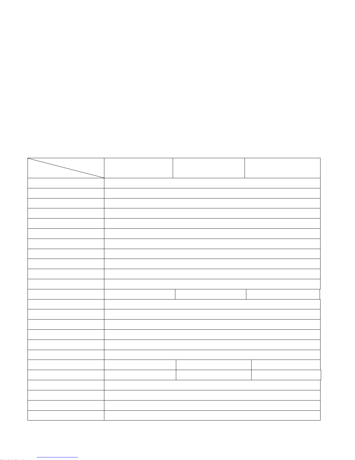
z 1 x 2.5” HDD space & 1 x CF External Slot
z Support 11~32V/DC Input, support AT/ATX mode
1.2 Specifications
Model No.
Specs :(%6$:(%6% :(%6&
CPU Supports Intel® FCBGA8 45nm Atom™ N270 Processor 533 MHz
Chipset Intel® 945GSE + ICH7-M Chipset
System Memory 1 x DDR2 SO-DIMM Socket, Support DDR2 533 up to 2GB
Storage support 1 x 2.5” SATA HDD space and 1 x External CF Slot
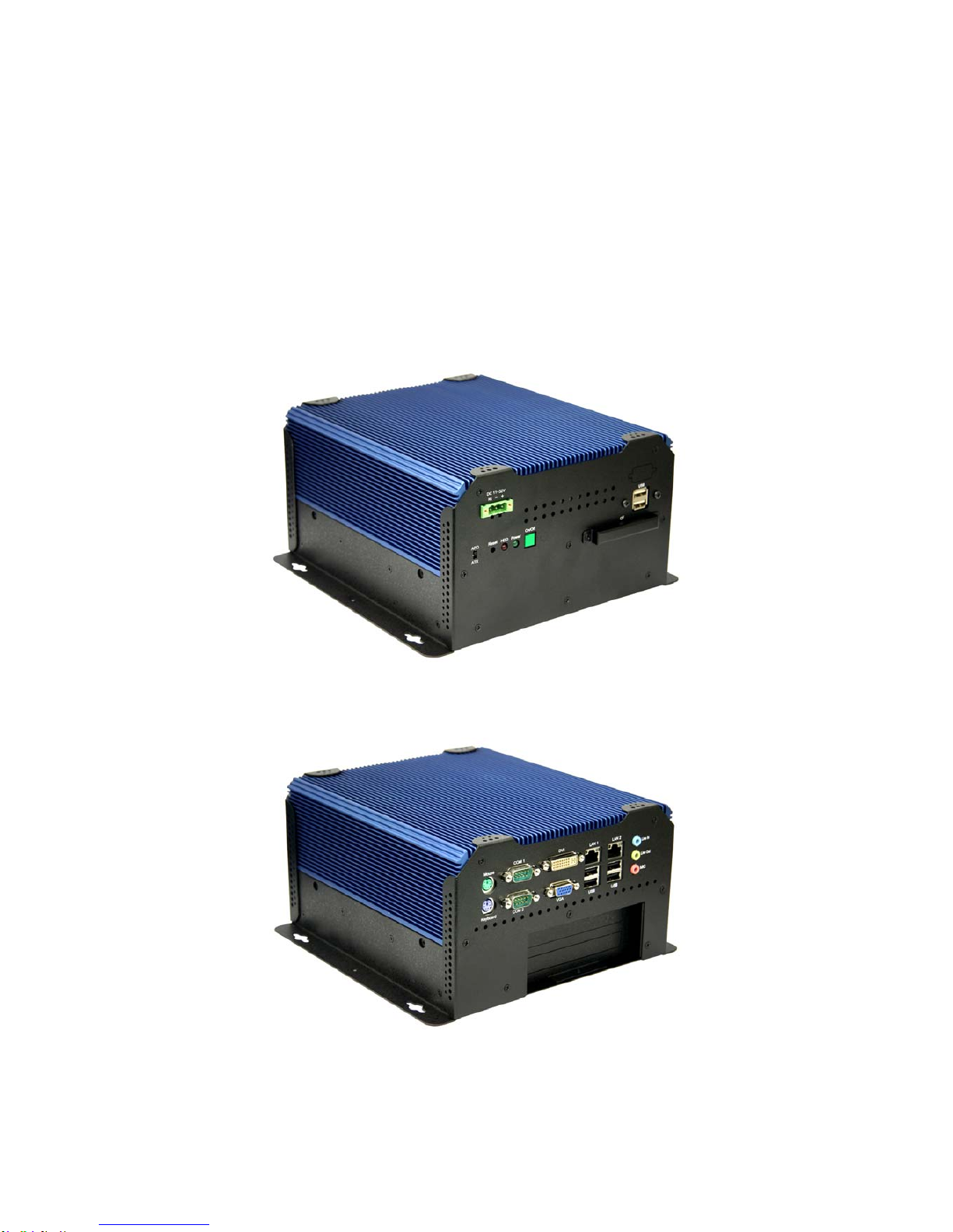
VGA 1x VAG port
DVI 1 x 24pin DVI port
Keyboard & Mouse 2 x PS/2 for Keyboard and Mouse Connectors
Serial Port 2 x RS-232
Ethernet 2 x Gigabit LAN
USB Port 4 x USB port on the I/O side and 2 x USB on the front side
Audio 1 x Line-in, 1 x Line-out, 1 x MIC in
Expansion Slots None 1 x PCI slot 2 x PCI slots
Power Input DC 11~32V
Watchdog Timer Reset: 1 sec.~255 min. and 1 sec. or 1 min./step
OS support XP Pro, XP Embedded
Construction Alumina Molding & Heavy-duty steel chassis
Color Blue Heat sink and Black Chassis
Mounting Wall mount
Dimensions (WxHxD) 203.5 x 230 x 80 mm 203.2 x 226.5 x 103.3 mm 203.5 x 230 x 125 mm
Net Weight 4.5kgs 4.5kgs 5kgs
Operating Temperature 0~50℃
Storage Temperature -20~60℃
Relative Humidity 10%~95% (non-condensing)
Certificate Meet CE / FCC Class A

:(%6$ User Manual 6
1.3 Dimensions
Figure 1.1: Dimensions of the :(%6$

:(%6$ User Manual 7
Figure 1.2: Dimensions of the :(%6%

:(%6$ 8
Figure 1.3: Dimensions of the :(%6&
.

:(%6$ User Manual 9
1.4 Mainboard
Figure 1.4: Mainboard Overview
1.5 Safety Precautions
Follow the messages below to avoid your systems from damage:
* Avoid your system from static electricity on all occasions.
* Prevent electric shock. Don‘t touch any components of this card when the card is power-on.
Always disconnect power when the system is not in use.
*Disconnect power when you change any hardware devices. For instance, when you connect
a jumper or inst all any cards, a surge of power may damage the electronic c omponents or
the whole system.

WEBS-1108A User Manual 10
1.6 Brief Description of the :(%6
The :(%6 is a power-optimized and delivers robust performance-per-watt for
cost-effective embedded Box PC, powered by an Atom™ N270 processor, implemented in 45nm
technology. The system supporting 6 USB 2.0 ports, 2x COM Ports, 1 x VGA, 1 x DVI, 1 x PCI slots
(WEBS-1108B only) or 2x PCI slots ( WEBS-1108C only), 1 x SATA HDD, 1 x external CF slot etc. It is ideal for
for kiosks, POS systems, airport terminal controllers, digital entertainments, etc. and running factory
operations from small visual interface and maintenance applications to large control process
applications. The WEBS-1108 works very well along with any of our Display Monitor series. It absolutely
can provide an easy way to perform control and field maintenance. It comes with a DC11~32V
wide-ranging power input.
Figure 1.5: Front View of WEBS-1108C
Figure 1.6: Rear View of WEBS-1108C

WEBS-1108A User Manual 11
Chapter 2__________Hardware Installation
2.1 Installing the Memory
The motherboard comes with one 200- pin Double Dat a Rate 2 (DDR2) Small Outline Dual Inline
Memory Modules (SO-DIMM) sockets.
A DDR2 module has the same ph ysical dimensions as a DDR DI MM but has a 200-pin footprint
compared to the 184-pin DDR DIMM. DDR2 DIMMs are notched differently to prevent installation on a
DDR DIMM socket. The following figure illustrates the location of the sockets:
200-Pin DDR2 SO-DIMM sockets
Memory Configurations
You may install 64 MB, 128 MB, 256 MB, 512 MB and up to 2 GB unbuffered ECC or non-ECC DDR
SO-DIMMs into the SO-DIMM sockets using the memory configurations in this section.
Installing a DIMM
Make sure to unplug the power supply before adding or removing
SO-DIMMs or other system components. Failure to do so may cause
severe damage to both the motherboard and the components.

WEBS-1108A User Manual 12
1. Unlock a SO-DIMM socket by pressing the retaining clips outward
2. Align a SO-DIMM on the socket such that the notch on the SO-DIMM matches the
break on the socket.
3. Firmly insert the SO-DIMM into the socket until the retaining clips snap back in place
and the SO-DIMM is properly seated.
z A DDR2 SO-DIMM is keyed with a notch so that it fits in only one
direction. DO NOT force a SO-DIMM into a socket to avoid
damaging the SO-DIMM.
z The DDR2 SO-DIMM sockets do not support DDR SO-DIMMs. DO
NOT install DDR SO-DIMMs to the DDR2 SO-DIMM socket.
Removing a SO-DIMM
1. Simultaneously press the retaining clips outward to unlock the SO-DIMM.
Support the SO-DIMM lightly with your fingers when pressing the
retaining clips. The SO-DIMM might get damaged when it flips out with
extra force.
2. Remove the SO-DIMM from the socket.

WEBS-1108A User Manual 13
2.2 Inst allation of HDD
2.2.1 Removing bottom cover
Use screwdriver to remove the bottom cover screws.
Keep the safely for later use. As shown.
2.2.2 Removing HDD Bracket
Disengage the housing of Ha rd disk drive. Just
unscrew the 4 screws , you c an easily fin d the HDD. As
shown.
2.2.3 Connecting Cable to HDD
Connect the cable to the HDD, making sure that the red
stripe of the cable is on the right side (if connected with
the top of the HDD facing upward).
** Onboard one Compact Flash slot as circled in the
picture
2.2.4 Tightening HDD
Tightly fasten the four screws as circled to secure the
HDD.
2.2.5 Installing HDD
Get the 4 screws tightened onto the chassis as shown in
the picture.

WEBS-1108A User Manual 14
2.3 Installation of PCI Expansion Add on Cards
2.3.1 Removing bottom cover
Use screwdriver to remove the bottom cover 27 screws.
Keep the safely for later use. As shown.
2.3.2 Support 1 x PCI slot (WEBS-1108B only)
Support 2 x PCI slots (WEBS-1108C only)
Shown in the picture are the one PCI expansion slots for
addon. The location of the 1 x PCI expansion slot card is
found by the side of the rail.
2.3.3 Insert the PCI Card
Now slide an addon into the slot of the PCI as circled in
the picture and making sure the golden part of the card is
evenly aligned with the slot of the PCI. Then carefully
push the card deep into the slot.
2.3.4 Tightening PCI bracket
Now get the addon secured by tightening the screw as
circled in the picture.
** Support Card size of PCI : 115 mm x 210mm
2.3.5 finish the installation
To finish the job, get the 27 screws tightened onto the
chassis as shown in the picture.

WEBS-1108A User Manual 15
2.4 Installing the Jumpers
2.4.1. Clear RTC RAM (CLRTC)
This jumper allows you to clear the Real Time Clock (RTC) RAM in CMOS. You can clear the CMOS
memory of date, time, and system setup parameters by erasing the CMOS RTC RAM data. The
onboard button cell battery powers the RAM data in CMOS, which include system setup information
such as system passwords.
To erase the RTC RAM:
1. Turn OFF the computer and unplug the power cord.
2. Remove the onboard battery.
3. Move the jumper cap from pins 1-2 (default) to pins 2-3. Keep the cap on pins 2-3 for about 5~10
seconds, then move the cap back to pins 1-2.
4. Re-install the battery.
5. Plug the power cord and turn ON the computer.
6. Hold down the <Del> key during the boot process and enter BIOS setup to re-enter data.
Except when clearing the RTC RAM, never remove the cap on CLRTC
jumper default position. Removing the cap will cause system boot failure!
You do not need to clear the R TC when the system hangs due to
overclocking. For system failure due to overclocking, use the C.P .R.
(CPU Parameter Recall) feature. Shut down and reboot the system so
the BIOS can automatically reset parameter settings to default values.

WEBS-1108A User Manual 16
2.4.2. COM1 RI, +12V and +5V Power Select (JCOMPWR1, JCOMPWR2)
This jumper allows you to select COM1 RI, +5V and +12V power. Set JCOMPWR1 to pins
1-3 and JCOMPWR2 to pins 1-3 to select +5V power. And set JCOMPWR1 to pins 3-5 and
JCOMPWR2 to pins 1-3 to select +12V power. Then set JCOMPWR2 to pins 3-5 and
JCOMPWR1 to open for RI selection.
2.4.3. COM2 RI, +12V and +5V Power Select (JCOMPWR1, JCOMPWR2)
This jumper allows you to select COM2 RI, +5V and +12V power. Set JCOMPWR1 to pins
2-4 and JCOMPWR2 to pins 2-4 to select +5V power. And set JCOMPWR1 to pins 4-6
and JCOMPWR2 to pins 2-4 to select +12V power. Then set JCOMPWR2 to pins 4-6 and
JCOMPWR1 to open for RI selection.
2.4.4. COM3 RI, +12V and +5V Power Select (JCOMPWR3, JCOMPWR4)
This jumper allows you to select COM3 RI, +5V and +12V power. Set JCOMPWR3 to pins
1-3 and JCOMPWR4 to pins 1-3 to select +5V power. And set JCOMPWR3 to pins 3-5

WEBS-1108A User Manual 17
and JCOMPWR4 to pins 1-3 to select +12V power. Then set JCOMPWR4 to pins 3-5 and
JCOMPWR3 to open for RI selection.
2.4.5. COM4 RI, +12V and +5V Power Select (JCOMPWR3, JCOMPWR4)
This jumper allows you to select COM3 RI, +5V and +12V power . Set JCOMPWR3 to
pins 2-4 and JCOMPWR4 to pins 2-4 to select +5V power. And set JCOMPWR3 to pins
4-6 and JCOMPWR4 to pins 2-4 to select +12V power. Then set JCOMPWR4 to pins
4-6 and JCOMPWR3 to open for RI selection.
2.4.6. System Panel Connector (F_PANEL1)
This connector supports several chassis-mounted functions.
z System Power LED (2-pin PWRLED)
This 2-pin connector is for the system power LED. Connect the chassis power LED
cable to this connector. The system power LED lights up when you turn on the system

WEBS-1108A User Manual 18
power, and blinks when the system is in sleep mode.
z ATX Power Button/Soft-off Button (2-pin PWRSW)
This connector is for the system power button. Pressing the power button turns the
system on or puts the system in sleep or soft-off mode depending on the BIOS settings.
Pressing the power switch for more than four seconds while the system is ON turns the
system OFF.
z Hard Disk Drive Activity LED (2-pin HDLED)
This 2-pin connector is for the HDD Activity LED. Connect the HDD Activity LED cable
to this connector. The IDE LED lights up or flashes when data is read from or written to
the HDD.
z Reset Button (2-pin RESET)
This 2-pin connector is for the chassis-mounted reset button for system reboot without
turning off the system power.

WEBS-1108A User Manual 19
2.5 Connectors
Rear panel connectors
1. PS/2 mouse port (green). This port is for a PS/2 mouse.
2. Serial connector. This 9-pin COM1 port is for serial devices.
3. DVI connector—for EMX-945GSE-A1-DVIR only.
This 24-pin DVI port connects to a DVI monitor.
4 & 5. LAN (RJ-45) port. This port allows Gigabit connection to a Local Area Network (LAN)
through a network hub. Refer to the table below for the LAN port LED indications.
LAN port LED indications
6. Line In port (light blue). This port connects a tape, CD, DVD player, or other audio sources.
7. Line Out port (lime). This port connects a headphone or a speaker. In 4-channel, 6-channel, and
8-channel configuration, the function of this port becomes Front Speaker Out.
8. Microphone port (pink). This port connects a microphone.
9. USB 2.0 ports 3 and 4. These two 4-pin Universal Serial Bus (USB) ports are available for
connecting USB 2.0 devices.
10. USB 2.0 ports 1 and 2. These two 4-pin Universal Serial Bus (USB) ports are available for
connecting USB 2.0 devices.
ACT/ LINK LED SPEED LED
Status Description Status Description
OFF No link OFF 10Mbps connection
Orange Linked Orange 100Mbps connection
Blinking Data activity Green 1Gbps connection

WEBS-1108A User Manual 20
11. VGA port. This 15-pin VGA port connects to a VGA monitor.
12. Serial connector. This 9-pin COM2 port is for serial devices.
13. PS/2 keyboard port (purple). This port is for a PS/2 keyboard.
1.9.2 Internal connectors
1. Front panel audio connector (10-pin AAFP1)
This connector is for a chassis-mounted front panel audio I/O module that supports either HD Audio or
legacy AC’97 audio standard.
It is recommended that you connect a high-definition front p anel audio
module to this connector to avail of the motherboard’ s high ‑definition
audio capability.
This manual suits for next models
2
Table of contents
Other Portwell Desktop manuals

Portwell
Portwell WEBS-85H1 User manual

Portwell
Portwell LYNX-6000 Series User manual

Portwell
Portwell LYNX- 6000 Series User manual

Portwell
Portwell WEBS-35C6 User manual

Portwell
Portwell WEBS-45H3 User manual

Portwell
Portwell WEBS-35C1 User manual

Portwell
Portwell COM Express PCOM-B653VGL User manual

Portwell
Portwell WEBS-45H1 User manual