Portwell LYNX-6000 Series User manual

LYNX- 6000 Series
User's Manual
Version 1.0
Copyright © Portwell, Inc., 2019. All rights reserved.
All other brand names are registered trademarks of their respective owners.

Preface
Table of Contents
How to Use This Manual
Chapter 1 System Overview.......................................................................................................1-1
1.1 Introduction ....................................................................................................... 1-1
1.2 Check List........................................................................................................... 1-1
1.3 Product Specification........................................................................................ 1-2
1.4 Mechanical Dimension..................................................................................... 1-3
Chapter 2 System Installation....................................................................................................2-1
2.1 M.2 Key E 2230 Wifi Module Installation...................................................... 2-1
2.2 M.2 Key B 2242 and Mini PCIe expansion Installation ............................... 2-2
2.3 Wall Mounting Device Installation ................................................................ 2-3
2.4 DIN-rail Mounting Device Installation.......................................................... 2-3
2.5 Getting Started................................................................................................... 2-4
2.6 External Antenna installation.......................................................................... 2-4
2.7 I/O Interfaces .................................................................................................... 2-5
2.7.1 Front View................................................................................................. 2-5
2.7.2 Rear View .................................................................................................. 2-6
Chapter 3 Important Instructions ..............................................................................................3-1
3.1 Note on the Warranty....................................................................................... 3-1
3.2 Exclusion of Accident Liability Obligation ................................................... 3-1
3.3 Liability Limitations / Exemption from the Warranty Obligation............ 3-1
3.4 Declaration of Conformity............................................................................... 3-1

Preface
How to Use This Manual
The manual describes how to configure LYNX- 6000 Series system to meet various operating
requirements. It is divided into three chapters, with each chapter addressing a basic
concept and operation of LYNX- 6000 Series system.
Chapter 1: System Overview. Present what may have in the box and give an overview of the
product specifications and basic system architecture for this fan-less embedded system.
Chapter 2: System Installation. Show the definitions and locations of all the interfaces and
describe a proper installation guide so that can easily configure the system.
Chapter 3: Important Instructions. Indicate some instructions which must be carefully
followed when the fan-less embedded system is used.
The content of this manual is subject to change without prior notice. These changes will be
incorporated in new editions of the document. The vendor may make supplement or
change in the products described in this document at any time.
Revision History
Revision
Date
Details of Change(s)
V1.0
2019/12/25
Initial Release

System Overview
LYNX-6000 Series User’s Manual 1-1
Chapter 1
System Overview
1.1 Introduction
Portwell Inc., a world-leading innovator in the Industrial PC (IPC) market, announced LYNX-
6000 Series system, a compact, fan-less and cable-less PC adapting low power Intel®Apollo
Lake processor. Developed to meet heavy industrial standards, the rugged design makes
sure its reliability as well as stability to work in harsh environment.
The modular design enhances the flexible of I/O demand and offers more opportunities to
fulfilled different applications. LYNX- 6000 Series is empowered by Intel® Celeron® N3350
(6W TDP), which integrates the low power the 8th generation Intel® HD Graphics
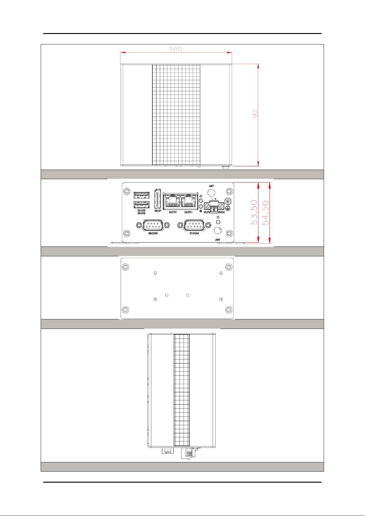
architecture. The palm-sized LYNX-6000 series includes LYNX-6110, LYNX-612E and
LYNX-612G system, and this series provides basic features which is 4GB onboard LPDDR4,
2400 MT/s, non-ECC, up to 8GB; two USB 3.0; one DisplayPort (DP) with resolution up to
3840 x 2160; two Ethernet RJ-45 LAN port; and 32GB onboard eMMC 5.0 flash, up to 256GB;
one M.2 Key E 2230 for wireless module. In addition, through the modular design,
LYNX-6000 series provides extended I/O interfaces e.g. LYNX-612E features except not only
the basic I/O but also two COM port (1x RS-232; 1 x RS-232/422/485 BIOS Configurable);
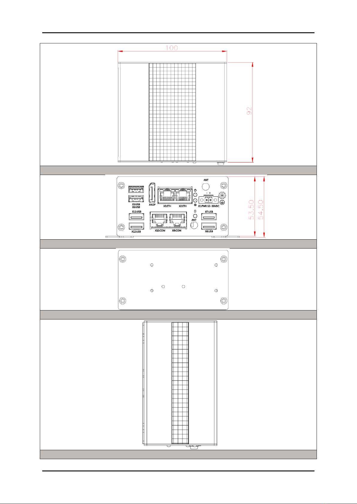
one M.2 Key B 2242; one full-size Mini-PCIe expansion. In LYNX-612G , it applies with
extended I/O interface two RS-232 COM port; four USB 2.0; one M.2 Key B 2242; one
full-size Mini-PCIe expansion.
The robust, fan-less design makes the LYNX- 6000 Series durable in harsh environment
applications, such as industrial automation, smart factory, edge computing, and IIoT
gateway applications. The rugged and compact LYNX- 6000 Series supports a temperature
range from 0ºC to 50ºC for harsh environment operation. In addition, it has already passed a
vibration test of DIN-rail mounting 1Grms/ 10~500Hz and a shock test of 15G, assuring its
solidity and reliability. In addition, the system accepts 12V-30VDC input voltage.
1.2 Check List
The LYNX- 6000 Series package should cover the following basic items:
One LYNX- 6000 Series System
Other Accessories
If any of these items is damaged or missing, please contact your vendor and keep all packing
materials for future replacement and maintenance.

System Overview
LYNX-6000 Series User’s Manual 1-2
1.3 Product Specification
Model Name
LYNX-6110
LYNX-612E
LYNX-612G
Processor
Intel® Celeron® N3350, 2 cores, 1.1GHz/2.4 GHz, 6W TDP
Memory
4GB onboard LPDDR4, 2400 MT/s, non-ECC; up to 8GB (Optional)
Storage
32GB onboard eMMC 5.0 flash; up to 256GB (Optional)
Power Input
12-30VDC (+/- 20%)
Operating System
Windows® 10 IoT Enterprise (64bit); Yocto v2.7
Expansion
1x M.2 Key E 2230 for wireless module
Basic I/O Interface
Power Connector
1x 2-Pin Terminal Block
Ethernet
2x 10/100/1000 GbE (Intel® I210)
USB
2x USB 3.0
Display
1x DP v1.4 4096 x 2160 @ 60Hz
Extended I/O Interface
COM/Console
N/A
1x RS-232; 1x RS-232/422/
485(BIOS Configurable)
2x RS-232
USB
N/A
N/A
4x USB 2.0
Expansion
N/A
1x M.2 Key B 2242 for storage
1x full-size Mini-PCIe
1x M.2 Key B 2242 for storage
1x full-size Mini-PCIe
Environmental
Storage Temp.
-40 °C ~ 85 °C
Operating Temp.
0°C ~ 50°C
Permissible Humidity
5-95% RH operating, non-condensing; 5-95% RH storage, non-condensing
Vibration
1G with DIN-rail mounting (EN 60068-2-6)
Shock
15G with 11 ms impulse length, 18 shocks in total (EN 60068-2-27)
Certification
CE (EN 55032; EN 55024/ EN 55035)
CE (EN 61000-6-4; EN 61000-6-2)
FCC (Part 15 Subpart Class A)
LVD (EN 62368)
Mechanical
Degree of Protection
IP 30
Dimension (mm)
100x40x92
100x53.5x92
Net Weight (Kg)
0.42
0.53
Expansion
N/A
1x M.2 Key B 2242 for storage
1x full-size Mini-PCIe
1x M.2 Key B 2242 for storage
1x full-size Mini-PCIe
Mounting
DIN-rail / Wall Mount
Cooling
Fan-less

System Overview
LYNX-6000 Series User’s Manual 1-3
1.4 Mechanical Dimension
Top view of LYNX-6110
Front view of LYNX-6110
Back view of LYNX-6110
Side view of LYNX-6110

System Overview
LYNX-6000 Series User’s Manual 1-4
Top view of LYNX-612E
Front view of LYNX-612E
Back view of LYNX-612E
Side view of LYNX-612E

System Overview
LYNX-6000 Series User’s Manual 1-5
Top view of LYNX-612G
Front view of LYNX-612G
Back view of LYNX-612G
Side view of LYNX-612G

System Overview
LYNX-6000 Series User’s Manual 1-6
Wall Mounting of LYNX-6000 Series
Din Rail mounting view of LYNX-6000 Series

System Installation
LYNX-6000 Series User’s Manual 2-1
Chapter 2
System Installation
This chapter provides you with instructions to set up your system. Definitions and
locations of all the interfaces are described so that you can easily configure your system.
2.1 M.2 Key E 2230 Wifi Module Installation
Step 1. Remove 2 screws at the bottom of
the front bracket.
Step 2. Remove 4 screws from the rear
bracket. Remove the rear bracket.
Step 3.
Pull out the bottom heat sink.
Step 4. Turn around the system, you can find
M.2 Key E 2230 socket and Wifi module can
be installed on it.
Step 5. Finishing the installation, put the
bottom heat sink back to the initial position.
Lock the front/rear bracket by screws.
Note:
Make sure to fasten the screw back with
proper torque (5kgf-cm) by torque wrench
on LYNX-6000. Improper torque may cause
the damage of screw thread on the
aluminum chassis.

System Installation
LYNX-6000 Series User’s Manual 2-2
2.2 M.2 Key B 2242 and Mini PCIe expansion Installation
NOTE:
Expansion card may various for different model, please check specification of each model.
Step 1. Remove 2 screwsat the bottom of
the front bracket.
NOTE: Need to remove the screw of COM
port for some specific model.
Step 2. Remove all 4 screws from the rear
bracket. Remove the rear bracket.
Step 3. Pull out the bottom heat sink.
Step 4. Turn around the system, you can
find Mini PCI-e and M.2 Key B 2242 card
socket and the expansion cards can be
installed on it.
Step 5. Finishing the installation, put the
bottom heat sink back to the initial position.
Lock the front/rear bracket by screws.
Note:
Make sure to fasten the screw back with
proper torque (5kgf-cm) by torque wrench
on LYNX-6000. Improper torque may cause
the damage of screw thread on the
aluminum chassis.
Mini PCIe
M.2 Key B 2242

System Installation
LYNX-6000 Series User’s Manual 2-3
2.3 Wall Mounting Device Installation
Step 1. Fasten the Wall Mounting bracket
by screws (M3 x 5L) on the LYNX-6000
series.
Step 2. Choose the correct type of mounting
surface and securely attach the LYNX-6000
series on it (desk/wall). Ensure that the
attaching hardware is in the small section of
the keyholes.
2.4 DIN-rail Mounting Device Installation
Step 1. Fasten the DIN-rail Mounting
bracket by screws (M3 x 5L) on the
LYNX-6000 series.
Suitable for 35mm (W), 7.5mm(H) DIN-rail.
Step 2. Clip the DIN Rail onto the device
and make sure it has been locked tightly

System Installation
LYNX-6000 Series User’s Manual 2-4
2.5 Getting Started
Step 1. Chassis Grounding
There is an easy-to-connect chassis
grounding point to use
Step 2.Connecting Power
This product is intended to be supplied by
a Listed Power Adapter or DC power
source, rated 10-30Vdc, 2A and Tma 50
degree C, if need further assistance, please
contact us for further information.
2.6 External Antenna installation
Included with the installed card is an antenna (1) that attaches to a connector on the
front of the unit (2). Since the LYNX-6000 Series is often installed within an enclosure, it
may be advisable to install the antenna on the exterior of the enclosure with
appropriate length antenna cable rather than directly to the IPC.

System Installation
LYNX-6000 Series User’s Manual 2-5
2.7 I/O Interfaces
2.7.1 Front View
LYNX-6110
LYNX-612E
LYNX-612G

System Installation
LYNX-6000 Series User’s Manual 2-6
2.7.2 Rear View
LYNX-6110
LYNX-612E
LYNX-612G

System Installation
LYNX-6000 Series User’s Manual 2-7
USB3.0
Two USB 3.0 (Universal Serial Bus) ports. USB 3.0 ports utilize a blue connector.
DP:
DP (Display Port) display output
LAN:
Two Gigabit Ethernet (10/100/1000 Mbits/sec) LAN ports by using Intel I210 Gigabit LAN
Controller.
Activity Link LED
Speed LED
Status
Description
Status
Description
Off
No link
Off
10Mbps
Connection
Orange
Linked
Orange
100Mbps
Connection
Orange(Blink)
Data activity
Orange(Blink)
1 Gbps
Connection
LED Indicator
Two LED indicator show the operating information.
Function*
Status
Description
Power
Power On
Solid Green
Power Off
Off
Run Status
(GPIO)
Run
Flash Green
Off
Off
*: Need to auto detection functionality while power applied.

System Installation
LYNX-6000 Series User’s Manual 2-8
COM
Serial (COM): D-SUB 9 serial ports are available for use, which is configurable as either
RS-232, RS-422, or RS-485 by BIOS setting. The function of the pins in the D-SUB 9
connector varies with the different configuration settings on different model, please
check it on the datasheet.
D-SUB 9 pin
RS-232
RS-422
RS-485
1
DCD
TXD-
TXD-/RXD-
2
RXD
TXD+
TXD+/RXD+
3
TXD
RXD+
-
4
DTR
RXD-
-
5
GND
GND
GND
6
DSR
-
-
7
TRS
-
-
8
CTS
-
-
9
Ring indicator
-
-
Power Terminal:
2-pin screw-type terminal block is provided for connecting power to LYNX-6000 series.
Pin No.
Description
-
0 V DC
+
12-30VDC (+/-20%)
M.2 and Mini PCIe Card Socket
Disassemble the chassis of LYNX-6000 series, you will see M.2 and Mini PCIe card socket
on the main board or carrier board. The socket type are varies with different models.
Antenna
A M.2 Key E 2230 or Mini PCIe expansion support wireless module.

Important Instructions
LYNX-6000 Series User’s Manual 3-1
Chapter 3 Important Instructions
This chapter includes instructions which must be carefully followed when the LYNX-6000
Series is used.
3.1 Note on the Warranty
Due to their limited service life, parts which, by their nature, are especially subject to wear
are not included in the guarantee beyond the legal stipulations.
3.2 Exclusion of Accident Liability Obligation
Portwell, Inc. shall be exempt from the statutory accident liability obligation if users fail to
abide by the safety instructions.
3.3 Liability Limitations / Exemption from the Warranty Obligation
In the event of damage to the system unit caused by failure to abide by the hints in this
manual and on the unit (especially the safety instructions), Portwell, Inc. shall not be
required to respect the warranty even during the warranty period and shall be free from
the statutory accident liability obligation.
3.4 Declaration of Conformity
EMC
CE/FCC Class A
This equipment complies with Part 15 of the FCC Rules. Operation is subject to the following
two conditions:
1. This equipment may not cause harmful interference.
2. This equipment must accept any interference that may cause undesired operation.
Applicable Standards:
EN 55032
EN 55024/ EN 55035
EN 61000-3-2: 2006
EN 61000-6-2
EN 61000-6-4
FCC 47 CFR Part 15 Subpart Class A
Safety
EN 62368-1
This manual suits for next models
3
Table of contents
Other Portwell Desktop manuals

Portwell
Portwell COM Express PCOM-B653VGL User manual

Portwell
Portwell WEBS-1108A User manual

Portwell
Portwell WEBS-45H1 User manual

Portwell
Portwell WEBS-35C6 User manual

Portwell
Portwell LYNX- 6000 Series User manual

Portwell
Portwell WEBS-35C1 User manual

Portwell
Portwell WEBS-45H3 User manual

Portwell
Portwell WEBS-85H1 User manual