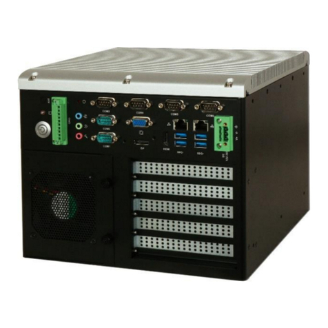
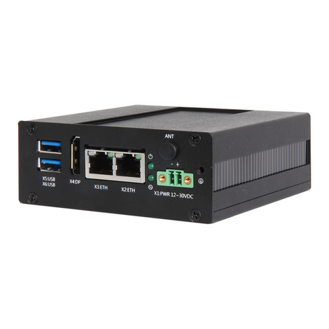
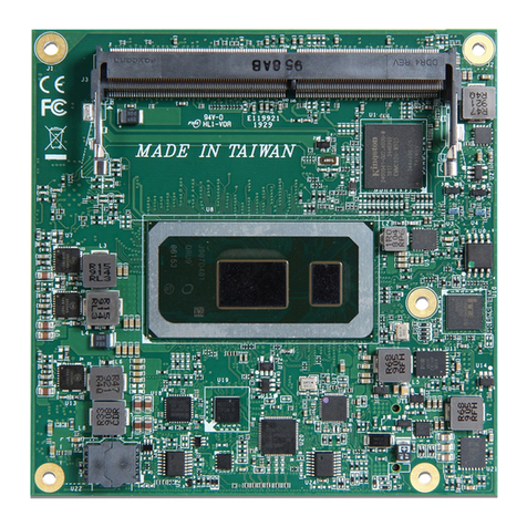
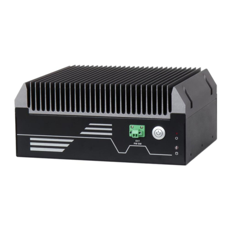
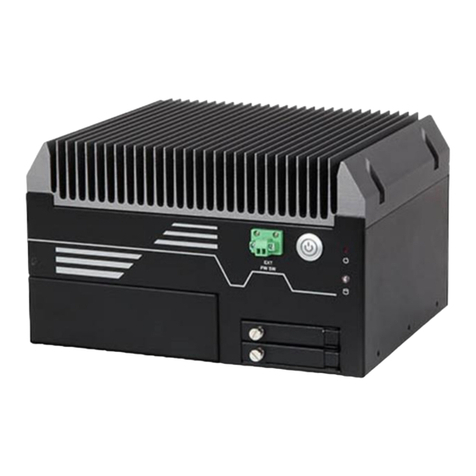
Portwell WEBS-85H1 User manual

WEBS-85H1
Fan-less Embedded System
AS5-3625
User's Manual
Version 1.2
Copyright © Portwell, Inc., 2022. All rights reserved.
All other brand names are registered trademarks of their respective owners.

Preface
Table of Contents
How to Use This Manual
Chapter 1 System Overview.......................................................................................................1-1
1.1 Introduction ....................................................................................................... 1-1
1.2 Product Specification........................................................................................ 1-2
1.3 Mechanical Dimension..................................................................................... 1-3
Chapter 2 System Installation....................................................................................................2-1
2.1 Embedded Board H/W Jumper Setting Introduction................................. 2-1
2.1.1 M/B overview .......................................................................................... 2-1
2.1.2 M/B Jumper setting................................................................................. 2-2
2.2 CPU and Memory module Installation.......................................................... 2-4
2.3 HDD/SSD Installation ..................................................................................... 2-7
2.4 Desk Mount Installation................................................................................... 2-9
2.5 I/O Interfaces .................................................................................................. 2-10
2.6 Getting Started................................................................................................. 2-12
Chapter 3 BIOS Setup Information..........................................................................................3-13
3.1 Entering Setup ................................................................................................. 3-13
3.2 Main .................................................................................................................. 3-14
3.3 Configuration .................................................................................................. 3-15
3.4 Security............................................................................................................ 3-37
3.5 Boot ................................................................................................................... 3-39
3.6 Save & Exit ....................................................................................................... 3-41
Chapter 4 Important Instructions ..............................................................................................4-1
4.1 Note on the Warranty....................................................................................... 4-1
4.2 Exclusion of Accident Liability Obligation ................................................... 4-1
4.3 Liability Limitations / Exemption from the Warranty Obligation............ 4-1
4.4 Declaration of Conformity............................................................................... 4-1
Chapter 5 Frequent Asked Questions.......................................................................................5-1
Portwell Software Service............................................................................................................5-3

Preface
How to Use This Manual
The manual describes how to configure your WEBS-85H1 system to meet various
operating requirements. It is divided into four chapters, with each chapter
addressing a basic concept and operation of Fan-less Embedded System.
Chapter 1: System Overview. Present what you have in the box and give you an
overview of the product specifications and basic system architecture for this fan-less
embedded system.
Chapter 2: System Installation. Show the definitions and locations of all the
interfaces and describe a proper installation guide so that you can easily configure
your system.
Chapter 3: BIOS Setup Information. Specify the meaning of each setup parameters,
how to get advanced BIOS performance and update new BIOS. In addition, POST
checkpoint list will give users some guidelines of troubleshooting.
Chapter 4: Important Instructions. Indicate some instructions which must be
carefully followed when the fan-less embedded system is used.
The content of this manual is subject to change without prior notice. These changes
will be incorporated in new editions of the document. The vendor may make
supplement or change in the products described in this document at any time.
Revision History
Revision
Date
Details of Change(s)
V1.0
2022/06/14
Initial Release
V1.1
2022/10/13
Updated Operation temperature condition in product
specification
V1.2
2022/10/13
Change system photo

System Overview
WEB-85H1 User’s Manual 1-1
Chapter 1 System Overview
1.1 Introduction
The WEBS-85H1 builds on Intel® desktop W480E chipset and takes advantages of
10th Generation Intel® Core™i3/i5/i7/i9 processors technologies that can support
dual DDR4 memory, Type II CFast and 2x 2.5”SSD slot for storage. Support three
Gigabit Ethernet ports, One M.2 E Key, One M.2 M Key and one Mini PCIe socket.
The WEBS-85H1 is an ideal platform with rich I/O and high resolution for POS,
kiosk, digital signage, and factory automation applications.
The system further takes advantage of the 10th generation Intel Core processor
technologies supporting dual-channel DDR4 memory up to 64GB.
Furthermore, the WEBS-85H1 Box PC includes rich I/O interfaces and fast
connectivity with three independent display (DisplayPort/HDMI 2.0/HDMI 1.4)
interfaces with resolution up to 4K, three Gigabit Ethernet ports, four COM ports,
Two USB 3.2 Gen2, four USB 3.2 Gen1 ports, one 8 bits DIO port, and
Mic-in/Line-out. Optional wireless via M.2 socket and 4G or LTE modules can be
added via a Mini PCIe socket.
The rugged, fan-less design makes the WEBS-85H1 durable in harsh environment
applications, such as factory automation and industrial automation. Portwell’s
WEBS-85H1 has already passed a vibration test of 1Grms/ 58.1~500Hz and a shock
test of 50G, 11 msec assuring its solidity and reliability.
In addition, the system accepts a wide input voltage range from 9V to 36V. This
power-source flexibility enables product usage in a variety of situations. Moreover,
the WEBS-85H1 is more than a robust and dependable embedded system with high
performance and graphics efficacy, its stylish mechanical design enhances the
system’s artistry. Potential applications include kiosk, intelligent digital security, IVI,
factory automation and surveillance applications, and many more.
System Overview
WEB-85H1 User’s Manual 1-2
Check List
The WEBS-85H1 package should cover the following basic items:
✓One WEBS-85H1 Fan-less Embedded System
✓One Desk Mount Kit
✓Other Accessories
If any of these items is damaged or missing, please contact your vendor and keep all
packing materials for future replacement and maintenance.
1.2 Product Specification
System
M/B
Proprietary
System Chipset
Intel®W480E chipset
CPU
10th Generation Intel® Core™i3/i5/i7/i9 Processors (35W TDP)
BIOS
AMI uEFI BIOS (SPI ROM)
System Memory
2x SO-DIMM sockets support DDR4 2400/2666 Non-ECC Up to 64 GB
Storage
- 1x Type II CFast slot
- 2x 2.5” SSD slots
Watchdog Timer
Programmable by embedded controller
H/W Status Monitor
HW WDT Enable (WDT_EN)
Expansion
- 1x Mini PCIe socket (supports mSATA or cellular module)
- 1x M.2 2242/60/80 M key socket (PCIe x4 & SATA mode)
- 1x M.2 2230 E key socket (supports CNVi, Wi-Fi/BT module)
External I/O
Series Ports
4x COM port (1x RS-232/422/485, CANbus (2.0 A/B)
selected by on board jumper)
Display
- 1x HDMI 2.0, supports up to 4096 x 2160 @ 60 Hz
- 1x HDMI 1.4, supports up to 4096 x 2160 @ 30 Hz
- 1x DP 1.2, supports up to 4096 x 2304 @ 60 Hz
USB
- 2x USB 3.2 Gen 2
- 4x USB 3.2 Gen 1
Audio
Mic-in / Line-Out
LAN
3x Gigabit Ethernet (Intel® I210-IT)
GPIO
4x DI, 4x DO
Other
2x nano SIM card slot
Power Supply Unit
Power Supply
9 to 36 VDC, 2-pin terminal block connector
Environment
Operating Temperature
-20°C ~ 40°C with Adapter
-20°C ~ 60°C with DC source
Storage Temperature
-40°C ~ 80°C
Relative Humidity
60°C, 95%RH non-condensing
Operating Vibration
Desk mount: 0.5 Grms (10 Hz to 500Hz)
System: 1Grms (10 Hz to 500Hz)
Operating Shock
Desk mount: 15G, 11 msec
System: 50G, 11 msec
Mechanical
Dimension (W x D x H)
210(W) x 250(D) x 119.7 (H) mm
Weight
4.5 Kg
Mounting
Desk mounting

System Overview
WEB-85H1 User’s Manual 1-3
1.3 Mechanical Dimension
front view of the WEBS-85H1 system
Rear view of the WEBS-85H1 system
Top view of the WEBS-85H1 system

System Installation
WEB-85H1 User’s Manual 2-1
11
13
12
1
1
3
1
4
1
6
1
7
1
8
1
9
1
2
1
5
1
10
Chapter 2 System Installation
This chapter provides you with instructions to set up your system. Definitions
and locations of all the interfaces are described so that you can easily configure
your system.
2.1 Embedded Board H/W Jumper Setting Introduction
2.1.1 M/B overview

System Installation
WEB-85H1 User’s Manual 2-2
2.1.2M/B Jumper setting
NO
Part
Description
Detail information
1
M.2 M-key slot
M.2 module (M-key, type 2242/2260/2280)
or M.2 B+M key TPU module
2
SPI TPM header
The SPI TPM header supports a TPM
system.
3
Chassis Intrude
header
The Chassis Intrusion header allows you to
connect an intrusion sensor or microswitch
for the chassis intrusion detection feature.
The default setting is close with a jumper
cap.
4
AT / ATX
power selection
The AT_ATX_SEL jumper allows you to
configure between AT or ATX power mode.
If the jumper is attached, ATX power mode
is set, if the jumper is removed, AT power
mode will be set. The default setting is ATX
mode.
5
HW WDT
Enable jumper
A watchdog timer is an electronic timer that
is used to detect and recover from computer
malfunctions. If the jumper is attached, HW
WDT_EN is enable, if the jumper is
removed, HW WDT_EN is disable.
6
ME Lock jumper
This jumper is used to lock the Intel®
Management Engine (IME). When the
Intel® ME is locked, no changes can be
made to the Intel® ME. This jumper should
only be set to ME Unlock when there is an
important update available from Intel® .

System Installation
WEB-85H1 User’s Manual 2-3
7
Mini PCIe /
mSATA switch
jumper
The Mini PCIe / mSATA switch jumper
allows you to set the Mini PCIe /mSATA
slot to either support a Mini PCIe card or
mSATA card. Default is SATA mode.
8
CAN/COM
switch jumpers
The CAN / COM switch jumpers allows
you to set COM4 to CAN bus or COM port.
Both jumpers need to be set to the setting for
the configuration to take effect.
9
I2C header
The I2C (Inter-Integrated Circuit) header
allows you to connect an I2C compatible IoT
security module.
10
M.2 E-key slot
The M.2 E-key slot allows you to install an
M.2 Wi-Fi module (E-key, type 2230), or M.2
A+E key TPU module.
11
Mini PCIe /
mSATA slot
This slot can only support either Mini PCIe
or mSATA, this can be adjusted with the
Mini PCIe / mSATA switch jumper.
12
External Power
Button
connector
The External Power Button connector
allows you to attach the External power
button terminal block to connect to an
external power button.
13
SATA conn
SATA conn

System Installation
WEB-85H1 User’s Manual 2-4
2.2 CPU and Memory module Installation
Equipped with CPU and Memory module by yourself if you purchase CPU or
Memory module locally.
Step 1. Loosen the screws of top
heatsink (there are 6 screws)
Step 2. Check system inside
Step 3. Open CPU Socket before
installing CPU.
Step 4. Open CPU socket protection
cover

System Installation
WEB-85H1 User’s Manual 2-5
Step 5. Install CPU. Please locate
notches on both side and pin one of
CPU first
Step 6. Install CPU successfully
Step 7. Make sure the thermal paste
can be applied uniformly on the heat
spreader.
Step 8. Fixed the screws of top heatsink
(there are 6 screws)
Install memory
Step 1. Loosen the 4 screws on the
system
Step 2. Loosen the 8 screws on the
system

System Installation
WEB-85H1 User’s Manual 2-6
Step 3. Loosen the 2 screws on the
system
Step 4. Open the cover of system
Step 5. Install DDR4 SO DIMM Memory
Module on the system
Step 6. Close the case and fix the 2
screws on the system
Step 7. Fix the 8 screws on the system
Step 8. Fix the 4 screws on the system

System Installation
WEB-85H1 User’s Manual 2-7
2.3 HDD/SSD Installation
Unique design of the HDD tray allows easy installation and maintenance of 2.5”
HDD/SSD. RAID function is supported with dual HDD/SSD design. (The height
must be less than 10mm)
Step 1. Loosen the 4 screws on the
system
Step 2. Loosen the 8 screws on the
system
Step 3. Loosen the 2 screws on the
system
Step 4. Open the cover of system
Step 5. Plug out SATA power and SATA
data cable from STAT conn board
Step 6. Loosen the screw on the case

System Installation
WEB-85H1 User’s Manual 2-8
Step 7. Install the two HDD/SSD and fix
the screws (8 pcs) from HDD/SSD kit
Step 8. Fix the screw (4pcs) on the case
Step 9. Plug SATA power and SATA
data cable into SATA conn board
Step 10. Close the cover of system
Step 11. fix the 2 screws on the system
Step 12. fix the 8 screws on the system

System Installation
WEB-85H1 User’s Manual 2-9
Step13. Fix the 4 screws on the system
Step 14. Finish HDD assembly.
2.4 Desk Mount Installation
Step 1. Prepare Desk mount kit and
screws x 4 pcs.
Step 2. System is ready for
assembling.
Step 3. Assemble the desk mount kit
with system and fasten it using 4 screws.
Step 4. Final picture.

System Installation
WEB-85H1 User’s Manual 2-10
2.5 I/O Interfaces
Front View
Function
Photo
Description
ANT1.ANT4
Antenna holes for LTE module
ANT2.ANT3
Antenna holes for WIFI module
Power
button
Press the power button to turn ON/OFF the system
DI/DO
The Isolation Digital Input / Output
LED
indicator
WD LED: Watchdog LED: LED color is Green.
Status ON: Watch dog timeout event.
Status OFF: Watch dog timeout event.
CFast LED: CFast LED: LED color is Green.
Status ON: CFast is reading/ Writing
data
Status OFF: CFast is not working
U1~U4 LED: U1~U2 color is RED,
U3~U4 color is Yellow.
U1~ U4 LED: Programmable
Status: ON/Blink/OFF/

System Installation
WEB-85H1 User’s Manual 2-11
Audio
Audio Jack for Mic-In, Line-In and Line-Out
LAN
Two Gigabit Ethernet (10/100/1000 Mbits/sec)
LAN ports by using Intel® I210-IT GbE Ethernet
ContN NNroller
USB
Support six USB (Universal Serial Bus) ports, four
USB 3.2 Gen1 and two USB 3.2 Gen 2.
COM
Support 4x COM ports,
COM1~COM3 default is RS-232,
COM4 default is RS-232 (1x RS-232/422/485,
CANBUS (2.0 A/B) selected by on board jumper)
EXT PWR
BTN
It is for remote system ON/OFF control.
DC In
Provide power connection of the system to the
main power source via DC power cable or AC/DC
power adapter.
SIM slot
Support 2x Nano SIM Card slots

System Installation
WEB-85H1 User’s Manual 2-12
2.6 Getting Started
It is easy to get the system started.
Step 1. Make sure the power supply
(9~36V) is connected properly
Step 2. Press the power button to turn on
the system
CFast
Support 1x CFast card slot
HDMI1
HDMI 1.4 display output
HDMI2
HDMI 2.0 display output
DP
DP (Display Port) 1.2 display output
HDD
Two removable 2.5" SSD trays for storage
installation

System Installation
WEB-85H1 User’s Manual 3-13
Chapter 3 BIOS Setup Information
The following section describes the BIOS setup program. The BIOS setup
program can be used to view and change the BIOS settings for the module. Only
experienced users should change the default BIOS settings.
3.1 Entering Setup
Power on the computer and the system will start POST (Power on Self Test)
process. When the message below appears on the screen, press <Delete> or
<ESC> key will enter BIOS setup screen.
Press<Delete> or <ESC> to enter SETUP
If the message disappears before responding and still wish to enter Setup, please
restart the system by turning it OFF and On or pressing the RESET button. It can
be also restarted by pressing <Ctrl>, <Alt>, and <Delete> keys on keyboard
simultaneously.
Press <F1> to Run General Help or Resume
The BIOS setup program provides a General Help screen. The menu can be easily
called up from any menu by pressing <F1>. The Help screen lists all the possible
keys to use and the selections for the highlighted item. Press <Esc> to exit the
Help Screen.

System Installation
WEB-85H1 User’s Manual 3-14
3.2 Main
3.2.1 Main
Use this menu for basic system configurations, such as time, date etc.
Feature
Description
Options
System Date
The date format is <Day>, <Month> <Date> <Year>. Use [+] or [-]
to configure system Date.
System Time
The time format is <Hour> <Minute> <Second>. Use [+] or [-] to
configure system Time.
3.2.2 Advanced
Use this menu to set up the items of special enhanced features
This manual suits for next models
1
Table of contents
Other Portwell Desktop manuals

Portwell
Portwell WEBS-45H1 User manual

Portwell
Portwell LYNX- 6000 Series User manual

Portwell
Portwell WEBS-35C1 User manual

Portwell
Portwell LYNX-6000 Series User manual

Portwell
Portwell COM Express PCOM-B653VGL User manual

Portwell
Portwell WEBS-45H3 User manual

Portwell
Portwell WEBS-35C6 User manual

Portwell
Portwell WEBS-1108A User manual
Popular Desktop manuals by other brands

Dell
Dell PowerConnect M8428-k Hardware reference manual

Lenovo
Lenovo ThinkCentre M57 user guide

Elo TouchSystems
Elo TouchSystems C-Series user guide

Digital Equipment
Digital Equipment PDP-8/A Operator's handbook

Lenovo
Lenovo ThinkCentre Edge 92 user guide

Lenovo
Lenovo ThinkCentre M55p Manual do utilizador