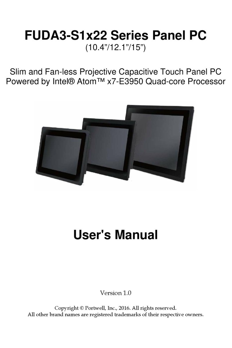
Portwell FUDA3-S1 12 Series User manual

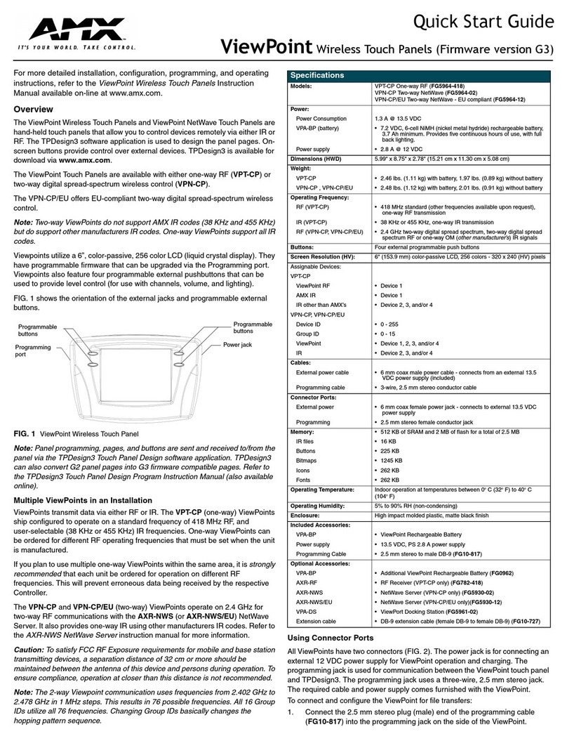
FUDA3-S1x12 Series Panel PC
(10.4”/12.1”/15”)
Slim and Fan-free 5-wire Resistive Touch Panel PC
Powered by Intel® Atom™ x7-E3950 Quad-core Processor
User's Manual
Version 1.0
Copyright © Portwell, Inc., 2022. All rights reserved.
All other brand names are registered trademar s of their respective owners.

Preface
Table of Contents
How to Use This Manual
Chapter 1 System Overview...................................................................................................................... 1-1
1.1 Introduction ..................................................................................................................................... 1-1
1.2 Check List ....................................................................................................................................... 1-3
1.3 Product Specification ...................................................................................................................... 1-5
1.4 Mechanical Dimension.................................................................................................................... 1-6
Chapter 2 System Installation................................................................................................................... 2-1
2.1 Embedded Board H/W Jumper Setting Introduction ....................................................................... 2-1
2.1.1 Main Board ........................................................................................................................... 2-1
2.1.2 Extension Board.................................................................................................................... 2-7
2.2 I/O Kit Installation............................................................................................................................ 2-9
2.3 Memory Module Installation .......................................................................................................... 2-11
2.4 HDD/SSD Storage Installation ...................................................................................................... 2-12
2.5 Half size Mini-PCIe WiFi/BT Module Installation ........................................................................... 2-13
2.6 Half size Mini-mSATA module Installation .................................................................................... 2-15
2.7 Getting Started.............................................................................................................................. 2-16
2.8 I/O Interfaces ................................................................................................................................ 2-17
2.8.1 Front View........................................................................................................................... 2-17
2.8.2 Rear View ........................................................................................................................... 2-18
2.8.3 Top View............................................................................................................................. 2-20
2.8.4 Side View............................................................................................................................ 2-20
2.9 Mounting Method .......................................................................................................................... 2-21
2.9.1 Panel Mount........................................................................................................................ 2-21
2.9.2 VESA®Mount...................................................................................................................... 2-22
Chapter 3 Driver Installation, Touch Usage and PET introduction........................................................ 3-1
3.1 How to Get the Driver...................................................................................................................... 3-1
3.2 Driver Installation ............................................................................................................................ 3-2
3.2.1 Intel® Chipset Driver Installation........................................................................................... 3-2
3.2.2 Intel® HD Graphics Driver Installation .................................................................................. 3-3
3.2.3 Intel® I210 Gigabit Ethernet Controller Driver Installation..................................................... 3-5
3.2.4 Intel® Trust Execution Engine Driver Installation.................................................................. 3-7
3.2.5 Intel® Serial IO Driver Installation......................................................................................... 3-9
3.2.6 Nuvoton Super I/O High-Speed Driver Installation.............................................................. 3-11
3.2.7 EETI eGalax Touch Driver Installation ................................................................................ 3-13
3.2.8 WiFi and Bluetooth Driver Installation ................................................................................. 3-17
3.3 Calibration of the Touch Screen.................................................................................................... 3-21
3.4 Portwell Software Service ............................................................................................................. 3-24
Chapter 4 BIOS Setup Information ........................................................................................................... 4-1
4.1 Entering Setup—Launch System Setup.......................................................................................... 4-1
4.2 Main ................................................................................................................................................ 4-2
4.3 Configuration................................................................................................................................... 4-3
4.4 Security......................................................................................................................................... 4-31
4.5 Boot............................................................................................................................................... 4-32
4.6 Save and Exit................................................................................................................................ 4-35
Chapter 5 Important Instructions.............................................................................................................. 5-1
5.1 Note on the Warranty...................................................................................................................... 5-1
5.2 Exclusion of Accident Liability Obligation........................................................................................ 5-1
5.3 Liability Limitations / Exemption from the Warranty Obligation ....................................................... 5-1
5.4 Declaration of Conformity................................................................................................................ 5-2
Chapter 6 Frequent Asked Questions ...................................................................................................... 6-1
Preface
How to Use This Manual
The manual describes how to configure your FUDA3-S1x12 Series Panel PC system to
meet various operating requirements. It is divided into four chapters, with each
chapter addressing a basic concept and operation of Fan-less Panel PC System.
Chapter 1: System Overview. Present what you have in the box and give you an
overview of the product specifications and basic architecture for Panel PC system.
Chapter 2: System Installation. Show the definitions and locations of all the
interfaces and describe a proper installation guide so that you can easily configure
your system.
Chapter 3: Driver Installation and Touch Usage Guide. Describe the operation
guide for included driver and software.
Chapter 4: BIOS Setup Information. Specify the meaning of each setup parameters,
how to get advanced BIOS performance and update new BIOS. In addition, POST
chec point list will give users some guidelines of trouble-shooting.
Chapter 5: Important Instructions. Indicate some instructions which must be
carefully followed when the Panel PC system is used.
Chapter 6: Frequent Asked Questions. Provide the answers for the most frequently
as ed questions.
The content of this manual is subject to change without prior notice. These changes
will be incorporated in new editions of the document. The vendor may ma e
supplement or change in the products described in this document at any time.
© 2022 Portwell, Inc. All Rights Reserved.
Portwell, Inc.
http://www.portwell.com.tw
Address : No. 242, Bo-Ai Street, Shu-Lin District, New Taipei City, 238, Taiwan
TEL:+886-2-7731-8888 ; FAX:+886-2-7731-9888
Revision History
Revision
Date Details of Change(s)
V1.0 2022/6/20
Initial Release

System Overview
FUDA3-S1x12 Series Panel PC User’s Manual 1-1
Chapter 1
System Overview
1.1 Introduction
FUDA3-S1x12 Series Panel PC is the next generation of Portwell’s standard Panel
PC product line. Keeping the successful experience in designing as well as mar eting
its ascendant, FUDA-S1x10/FUDA2-S1x11 Series Panel PC, in mind, FUDA3-S1x12
Series Panel PC aims at serving IPC customers with much more powerful HMI
solutions which provide high performance and low power consumption. Therefore,
FUDA3-S1x12 Series Panel PC adopts the latest Intel® Atom™ platform, x7-E3950
processor (12 W Max TDP, 2M Cache, 1.6 GHz up to 2.0 GHz) integrating Intel HD
Graphic Gen 9 engine, flexible I/O connectivity and 2 times higher GPU computing
power than FUDA2 series PPC (Intel® Atom™ E3845 platform).
Equipped with a 5-wire resistive type touch screen and a panel with at least
resolution of 1024 x 768 pixels, it is housed in an Aluminum bezel with anodizing
coating that has a full IP65 rated front panel. This feature allows FUDA3-S1x12 Series
Panel PC to be used extensively in harsh environments such as the operating
temperature from -25 to 60 ℃ degrees. The panel PC includes all required interfaces
for industrial application: 1 x HDMI port, 2 x Gigabit Ethernet ports, 1x USB OTG, 2 x
USB 3.0 ports, 2 x USB 2.0, 2 x RS-232/422/485 ports by Expansion: Option 0 it, 1 x
2.5" SATA HDD/SSD can be extract easily from externally, 1x Mini-mSATA can be
mounted on mother board for second storage capacity. One SMA Antenna holes
provide optional WiFi solution via Half-size WiFi Mini-PCIe module or optional LTE
solution via Full-size Mini-PCIe module with SIM soc et.
Furthermore, FUDA3-S1x12 Series offer a name plate customization service with
small MOQ for customer to design their logo, color and style. It is ideal solution for
customer to create itself unique product quic ly.
As we all now, UART port such as RS-232/422/485 is very important I/O to
communicate between device and device at factory. FUDA3 Panel PC adopt new
Super I/O chip to ma e UART ports support high-speed baud rate from 115.2K up to
maximum 921.6K under Windows 10. The advantage can solve I/O communication
slowly problem in factory automation environment and implement High-speed
UARTs Support

System Overview
FUDA3-S1x12 Series Panel PC User’s Manual 1-2
To fulfill different application needs and to secure the system from power input
change, the system accepts DC 12~24V wide range power input with 3-pin terminal
bloc connector for various operating environment. The FUDA3-S1x12 Series Panel
PC offers panel mounting and equipped with standard 75 x75, 100 x 100 mm VESA
mounting holes. It supports many mainstream operating systems, such as Windows
10 and Linux.

System Overview
FUDA3-S1x12 Series Panel PC User’s Manual 1-3
1.2 Check List
The FUDA3-S1x12 Series Panel PC pac age covers the following items:
Essential
One FUDA3-S1x12 Panel PC
Panel Size Model Name
10.4” FUDA3-S1012
12.1” FUDA3-S1212
15” FUDA3-S1512
Screws for HDD installation
M3X4L Screw 4 pieces
3-pin Terminal Bloc Connector (Female)
Optional
Panel Mount Kits
Panel Size Kits (pcs)
10.4” 8 pieces
12.1” 12 pieces
15” 16 pieces
60W Power Adapter with Power Cord (EU/US type) and Power Switch Cable
60W Power Ad pter
Power Cord (US type)
Power Cord (EU type)
Power switch c ble (from DC J ck to 3-pin TBC)

System Overview
FUDA3-S1x12 Series Panel PC User’s Manual 1-4
Selectable I/O Kit
2x RS-232/422/485, 2x USB 2.0
(Exp nsion: Option 0)
2x RS-232/422/485, 2x USB 2.0
(Exp nsion: Option 0)
If any of these items is damaged or missing, please contact your vendor and eep all
pac ing materials for future replacement and maintenance.

System Overview
FUDA3-S1x12 Series Panel PC User’s Manual 1-5
1.3 Product Specification
Model Name
FUDA
3
-
S101
2
FUDA
3
-
S121
2
FU
DA
3
-
S151
2
Display
LCD Size
10.4”
12.1"
15”
N/A
N
/A
Resolution
XGA 1024 x 768
XGA 1024 x 768
XGA 1024 x 768
N
/A
N
/A
rightness
450 cd/m
2
6
00 cd/m
2
450 cd/m
2
N
/A
N
/A
Contrast Ratio
3000:1
700:1
700:1
N
/A
N
/
A
acklight
LED type
LED type
LED type
N
/A
N
/A
Touch
Window
5
-
ire Resistive Single Touch
System
SOC
Intel
®
Atom™
x7
-
E3950
(
Quad
Core
1
.6
G
Hz
, 2M Ca
che,
up
2
.0
GHz)
Memory
DDR3L S
O
-
DIMM
1866
MHz max up to 8
GB
IOS
AMI
Graphics
Intel®
HD
Gen
9
Graphics
LVDS
Single/Dua
l Channel 24
-
bit
LA
N Chipset
Dua
l Intel
®
Gigabit Ethernet
Chipset
Aud
io
N/
A
Watchdog Timer
Programmable
1~255
secs
Storage Device
2.5" SATA HDD / SSD,
Min
i
-
mSATA
OS
indows 10 /
Linux™
I/O Interface
Series Port
2 x RS
-
232/4
22/485
(E
x
pansion: Option 0)
Display
1 x
HDMI
US
1
x
US
B OTG,
2
x USB 3.0, 2 x USB 2.0
(E
x
pansion: Option 0)
Ethernet
2 x Gigabit Ethernet
Others
1 x SMA Antenna hole for iFi/
LTE
Solution
Expansion
1 x
Full
-
size Mini
-
PCIe socket
,
1 x Half-size Mini-PCIe/Mini-mSATA (default: Mini-mSATA)
2 x RS
-
2
32/422/4
85,
1 x RS
-
23
2 (Expansion: option 1)
Mechanical
Mounting (mm)
VESA Mount 75 x 75 & 100 x 100 ; Panel Mount
Weight (Kg)(N)
3.5 Kg
4.3 Kg
5.3 Kg
N
/A
N
/A
Weight (Kg)(G)
5.8 Kg
6.2 Kg
8.2 Kg
N
/A
N
/A
Dimension
314 x 253 x 50.2
mm
343 x 282 x 53.2
mm
425.4 x 330 x 55.6
mm
N/A N/A
Power
Po
wer Supply
DC 12 ~ 24V input with 3
-
pin Terminal Block Connector
Consumption (Max)
3
3.5
(12V);
3
3
.6
(24V)
40.9
(12V);
3
9.4
(24V)
40.5
(12V);
40
.2
(24V)
N/A N/A
Consumption (Min)
1
1.8
(1
2V);
1
4
(24V)
1
2
.0
(12V);
12
.3
(24V)
1
1.2
(12V);
1
2
.
0
(24V)
N/A N/A
Power Adap
tor
D
C12V
~
24V I
nput
wi
th 3
-
p
in
T
erminal
Block
C
onnector
Environmental
OP /Storage Temp
-
2
5
~
6
0
℃
/
-
40~85
℃
(20~90% non
-
condensing)
Vibration
1.0G (
SSD/
M
i
ni
-
mSATA
) and 0.5G (H
DD) , Power on & 2.16G, Packaged; 5~500Hz
, IEC
6
0068
-
2
-
6
Shock
15G peak acceleration, 11 ms (Power on condition)
, IEC 60068
-
2
-
27
Drop
Package with Carton from 96.5 c
m (1
-
Corner, 3
-
Axis, 6
-
Face)
, ISTA
2A Standard
Front Panel
Protection
IP65 (Front) / IP20 (Rear) (IEC 60529 Edition 2.1 Standard)
Certif
ication
CE/FCC Class A
, UK
CA, EN
6236
8
-
1
, EN
61000
-
6
-
2, EN
61000
-
6
-
4

System Overview
FUDA3-S1x12 Series Panel PC User’s Manual 1-6
1.4 Mechanical Dimension
Front and side view of the FUDA3-S1012 system
Bac view of the FUDA3-S1012 system

System Overview
FUDA3-S1x12 Series Panel PC User’s Manual 1-7
Front and side view of the FUDA3-S1212 system
Bac view of the FUDA3-S1212 system

System Overview
FUDA3-S1x12 Series Panel PC User’s Manual 1-8
Front and side view of the FUDA3-S1512 system
Bac view of the FUDA3-S1512 system

System Overview
FUDA3-S1x12 Series Panel PC User’s Manual 1-9

System Installation
FUDA3-S1x12 Series Panel PC User’s Manual 2-1
Chapter 2
System Installation
This chapter provides you with instructions to set up your FUDA3-S1x12 Series Panel
PC. Definitions and locations of all the interfaces are described so that you can easily
configure your system.
2.1 Embedded Board H/W Jumper Setting Introduction
2.1.1 Main Board
FUDA3-S1x12 Series Panel PC adopts PEB-99A5 series mother board. You may
configure the Panel PC by setting jumpers of the mother board to match the needs of
your applications. To select any option, cover the jumper cap (SHORT) or remove
(NC) it from the jumper pins according to the following instructions.
*Note: NC stands for “Not Connect”.
Component side:

System Installation
FUDA3-S1x12 Series Panel PC User’s Manual 2-2
Solder side:
Connector and Jumper setting:
Connector
J1 Full-size Mini-PCIe Socket
J2 H lf-size Mini-PCIe/Mini-mSATA Socket
J3 SATA+PWR
J4 GPIO
J5 LPC Debug Port (For Port 80 debug c rd use)
J6 CMOS B ttery
J7 Customize I/O Slot
J8 RJ-45 Port
J9 RJ-45 Port
J10 USB 3.0 *2
J11 Termin l Block Connector
J12 HDMI Port
J13 USB OTG Port
J15 Front P nel
J16 Spe ker
J17 Spe ker
J18 LCD LVDS B cklight Control
J19 LCD LVDS Connector
J21 Microphone He der
J22 USB 2.0 Connector (For Touch bo rd connection use )
J23 Micro SIM C rd Socket (for J1 Full-size Mini-PCIe socket use)

System Installation
FUDA3-S1x12 Series Panel PC User’s Manual 2-3
Jumpers
JP1 P nel B cklight En ble Select (Def ult: 1-3, 2-4)
JP2 P nel Power Select (Def ult: 1-3)
JP3 CMOS Setting (Def ult: 1-2)
JP4 Mini-mSATA/mini-PCIe Select (Def ult 1-2: Mini-mSATA)
JP5 Auto Power On (Def ult: 2-3)
JPA1 COM1 RI Setting (Def ult: 3-4)
JPA2 COM2 RI Setting (Def ult: 3-4)
JPB1 COM3 RI Setting (Def ult:3-4)
JPB2 COM4 RI Setting (Def ult:3-4)
SW1 Reset Button
SW2 Power Button
D29 St te LED
J4: GPIO Connector (2*5 Pin Header/2mm):
PIN NO. DESCRIPTION PIN NO. DESCRIPTION
1 GPIO1 2 GPIO5
3 GPIO2 4 GPIO6
5 GPIO3 6 GPIO7
7 GPIO4 8 GPIO8
9 GND 10 +5V
J5: LPC Debug Port Pin Assignment
PIN NO. DESCRIPTION PIN NO. DESCRIPTION
1 LAD0 2 3.3V
3 LAD1 4 LPC_RESET
5 LAD2 6 LPC_FRAME
7 LAD3 8 LPC_CLCOK
10 GND
J11: Power Input Connector (Terminal Bloc s 3Px1/5.08mm female)
PIN NO.
DESCRIPTION
1
GND EARTH
2
Vin
-
3
Vin+
J15: Front Panel Connector (1*5 Pin Wafer/2mm)
PIN NO.
DESCRIPTION
1
LED (Hi: Green LED +; Low: Or nge LED -)
2 LED (Hi: Or nge LED+; Low: Green LED-)
3
Power Button
4
Power Button
5 NC

System Installation
FUDA3-S1x12 Series Panel PC User’s Manual 2-4
J18: LCD Inverter Power Connector (1*5 Pin wafer/2mm)
PIN NO.
DESCRIPTION
1
LCD_EN
A
B
LE
2
GND
3
+12V
4
LCD_BLADJ
5
+5V
J19: LCD LVDS Connector (2*15 Pin Hirose/1.25mm)
PIN NO.
Description
PIN NO.
Descripti
on
1 YAP0 2 YAM0
3
YAP1
4
YAM1
5
YAP2
6
YAM2
7
YAP3
8
YAM3
9
CLKAP
10
CLKAM
11
YBP0
12
YBM0
13
YBP1
14
YBM1
15
YBP2
16
YBM2
17
YBP3
1
8
YBM3
19
CLKBP
20
CLKBM
21
DDCPCLK
22
DDCPDATA
23
GND
24
NC
25
GND
26
GND
27
+LVDS
28
+LVDS
29 NC 30 +LVDS
J22: USB Port Connector (1*5 Pin Wafer/2mm)
PIN NO.
DESCRIPTION
1
+ 5V
2
USB_D3-
3
USB_D3+
4
GND

System Installation
FUDA3-S1x12 Series Panel PC User’s Manual 2-5
JP1: Panel Bac light Enable Select
PIN NO. DESCRIPTION
1-3 2-4
Short Short +5V High Active ★ Def ult
PIN NO. DESCRIPTION
1-3 4-6
Short Short +12V High Active
PIN NO. DESCRIPTION
2-4 3-5
Short Short +5V Low Active
PIN NO. DESCRIPTION
3-5 4-6
Short Short +12V Low Active
JP2: Panel Voltage Setup
PIN NO. DESCRIPTION
1-3 3-5 3-4 Volt ge
Short +3.3V TFT LCD ★ Def ult
Short +5V TFT LCD
+12V TFT LCD
JP3: CMOS Setup
PIN NO. DESCRIPTION
1-2 Norm l (Keep CMOS Setup) ★ Def ult
2-3 Cle r CMOS Setup
JP4: Mini-mSATA/Mini-PCIE Selection
PIN NO. DESCRIPTION
1-2 Mini-mSATA ★ Def ult
2-3 Mini-PCIe
JP5: Auto Power on
PIN NO. DESCRIPTION
1-2 Auto Power on ★ Def ult
2-3 Norm l
JPA1: COM2 Pin 9 Function Setup
PIN NO. DESCRIPTION
1-2 3-4 5-6
Short +5V Output
Short RI Function ★ Def ult
Short +12V Output

System Installation
FUDA3-S1x12 Series Panel PC User’s Manual 2-6
JPA2: COM1 Pin 9 Function Setup
PIN NO. DESCRIPTION
1-2 3-4 5-6
Short +5V Output
Short RI Function ★ Def ult
Short +12V Output
JPB1: COM3 Pin 9 Function Setup
PIN NO. DESCRIPTION
1-2 3-4 5-6
Short +5V Output
Short RI Function ★ Def ult
Short +12V Output
JPB2: COM4 Pin 9 Function Setup
PIN NO. DESCRIPTION
1-2 3-4 5-6
Short +5V Output
Short RI Function ★ Def ult
Short +12V Output
SW1: Reset Button
PIN NO. DESCRIPTION
Rele se Norm l
Push Reset
SW2: Power Button
PIN NO. DESCRIPTION
Rele se Norm l
Push Power on
D29: Reset Button
PIN NO. DESCRIPTION
3,4 (Red LED) HDD St te
1,2 (Green LED)
Power St te

System Installation
FUDA3-S1x12 Series Panel PC User’s Manual 2-7
2.1.2 Extension Board
FUDA3-S1x12 Series Panel PC can adopt different I/O extension board. You may
configure the Panel PC by different I/O it options to match mar et needs.
Option 0 (P -P1S2U2):
Option 1 (P -P1S3):
COM port RS-232/422/485 mode setup:
Note: Both COM1 & COM2 support RS-232/422/485 (selectable in BIOS menu).
RS-232 Mode Setup
PIN No.
Sign l Description PIN No.
Sign l Description
1 D t C rrier Detect (DCD) 2 Receive D t (RXD)
3 Tr nsmit D t (TXD) 4 D t Termin l Re dy (DTR)
5 GND 6 D t Set Re dy (DSR)
7 Request to Send (RTS) 8 Cle r to Send (CTS)
9 Ring Indic tor (RI)

System Installation
FUDA3-S1x12 Series Panel PC User’s Manual 2-8
RS-422 Mode Setup
PIN No.
Sign l Description PIN No.
Sign l Description
1 TX- 2 TX+
3 Rx+ 4 Rx-
5 GND 6 RTS-
7 RTS+ 8 CTS+
9 CTS-
RS-485 Mode Setup
PIN No.
Sign l Description PIN No.
Sign l Description
1 DATA- 2 DATA+
3 NC 4 NC
5 GND 6 NC
7 NC 8 NC
9 NC
Table of contents
Other Portwell Touch Panel manuals

Portwell
Portwell FUDA2-S1 21 Series User manual

Portwell
Portwell PEDA S1x30 Series User manual

Portwell
Portwell FUDA2-S1x11 Series User manual

Portwell
Portwell AUDA-S08BS V3 User manual

Portwell
Portwell LEAD-PPC-2150-X User manual

Portwell
Portwell FUDA3-S1-22 Series User manual

Portwell
Portwell EUDA 2 Series User manual

Portwell
Portwell LEAD-PND-2150 Series User manual