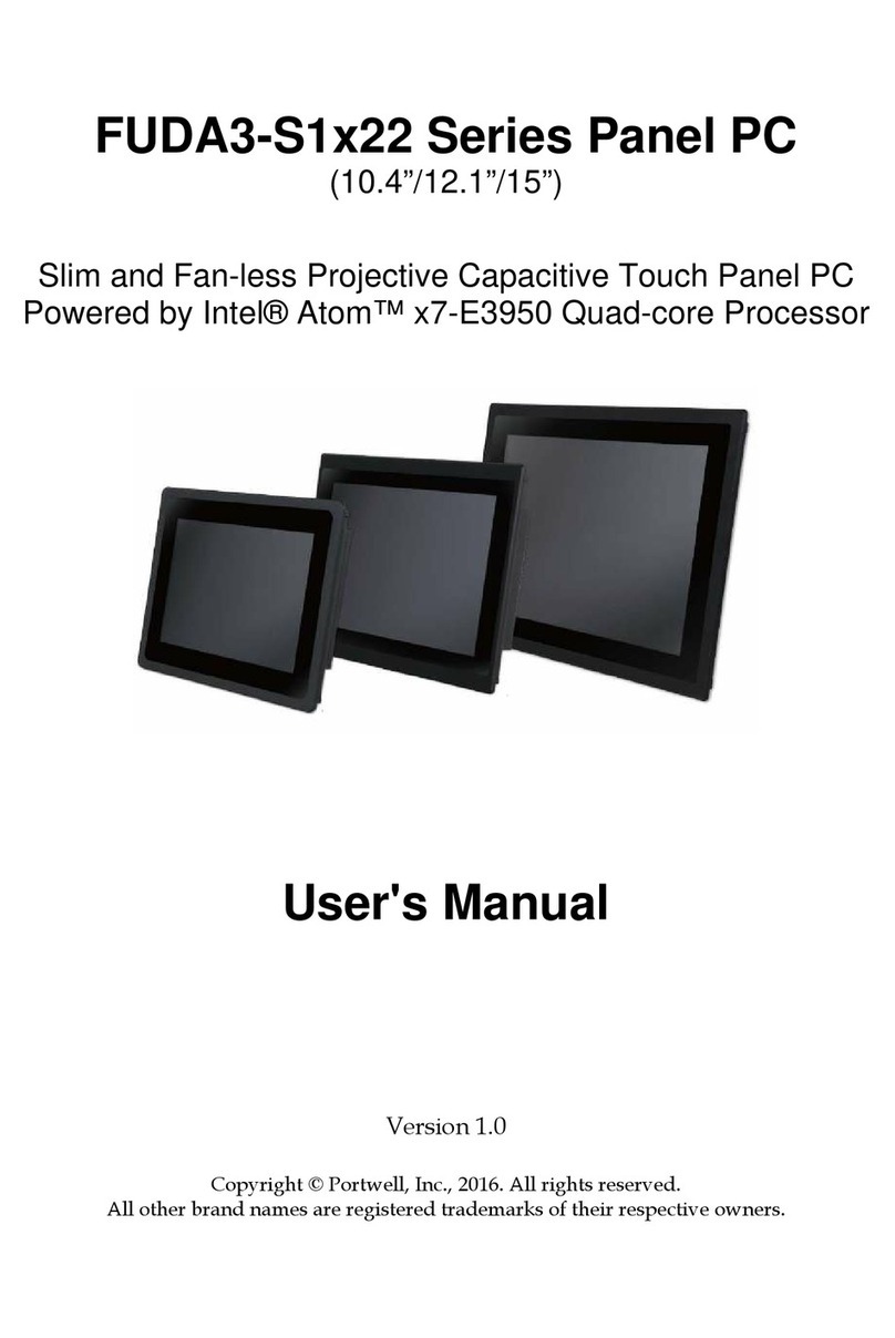
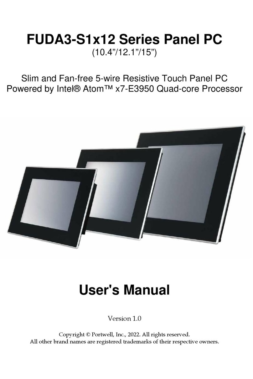
Portwell PEDA S1x30 Series User manual

PEDA-S1x30 Series Panel PC
(12.1”/15”/17”/19”/21.5”)
Modularized Fan-free Panel PC
With High Performance and Flexible Expansion Solution
Powered by Intel® Haswell ULT SoC Processor
User's Manual
Version 1.0
Copyright © Portwell, Inc., 2015. All rights reserved.
All other brand na es are registered trade arks of their respective owners.

Preface
Table of Contents
How to Use This Manual
Chapter 1 System Overview.......................................................................................................1-1
1.1 Introduction ....................................................................................................... 1-1
1.2 Check List ........................................................................................................... 1-2
1.3 Product Specification ........................................................................................ 1-3
1.4 Mechanical Di ension ..................................................................................... 1-4
Chapter 2 System Installation....................................................................................................2-1
2.1 HDD Installation ............................................................................................... 2-1
2.2 CFEX Installation .............................................................................................. 2-1
2.3 PCI/PCIe Card Installation ............................................................................. 2-2
2.4 Me ory Module Expansion ............................................................................ 2-4
2.5 Getting Started ................................................................................................... 2-6
2.6 I/O Interfaces .................................................................................................... 2-6
2.6.1 Front View ................................................................................................. 2-6
2.6.2 Rear View .................................................................................................. 2-7
2.7 Mounting Method ............................................................................................. 2-9
2.7.1 Panel Mount .............................................................................................. 2-9
2.7.2 VESA® Mount ........................................................................................ 2-10
Chapter 3 Driver Installation and Touch Usage Guide............................................................3-1
3.1 Driver Installation ............................................................................................. 3-1
3.2 Calibration of the Touch Screen ...................................................................... 3-1
Chapter 4 BIOS Setup Information............................................................................................4-1
4.1 Entering Setup—Launch Syste Setup ......................................................... 4-1
4.2 Main .................................................................................................................... 4-2
4.3 Syste Setup Utility ......................................................................................... 4-3
4.4 Configuration .................................................................................................... 4-3
4.5 Boot ................................................................................................................... 4-22
4.6 Security ............................................................................................................. 4-24
4.7 Exit ..................................................................................................................... 4-25
Chapter 5 Important Instructions ..............................................................................................5-1
5.1 Note on the Warranty ....................................................................................... 5-1
5.2 Exclusion of Accident Liability Obligation ................................................... 5-1
5.3 Liability Li itations / Exe ption fro the Warranty Obligation............ 5-1
5.4 Declaration of Confor ity ............................................................................... 5-1
Chapter 6 Frequent Asked Questions.......................................................................................6-1

Preface
How to Use This Manual
The anual describes how to configure your FUDA2-S1x11 Series Panel PC syste to
eet various operating require ents. It is divided into four chapters, with each
chapter addressing a basic concept and operation of Fan-less Panel PC Syste .
Chapter 1: System Overview. Present what you have in the box and give you an
overview of the product specifications and basic architecture for Panel PC syste .
Chapter 2: System Installation. Show the definitions and locations of all the
interfaces and describe a proper installation guide so that you can easily configure
your syste .
Chapter 3: Driver Installation and Touch Usage Guide. Describe the operation
guide for included driver and software.
Chapter 4: BIOS Setup Information. Specify the eaning of each setup para eters,
how to get advanced BIOS perfor ance and update new BIOS. In addition, POST
checkpoint list will give users so e guidelines of trouble-shooting.
Chapter 5: Important Instructions. Indicate so e instructions which ust be
carefully followed when the Panel PC syste is used.
Chapter 6: Frequent Asked Questions. Provide the answers for the ost frequently
asked questions.
The content of this anual is subject to change without prior notice. These changes
will be incorporated in new editions of the docu ent. The vendor ay ake
supple ent or change in the products described in this docu ent at any ti e.
Revision History
Revision
Date Details of Change(s)
V1.0 2015/7/1 Initial Release

System Overview
FUDA2-S1x11 Series Panel PC User’s Manual 1-1
Chapter 1
System Overview
1.1 Introduction
PEDA-S1x30 Series Panel PC sets a new standard in HMI solutions. Re arkable
advance and brand new features of this incredible syste akes it powerful for ost
industrial application arkets. By adopting the 4th generation Intel® CoreTM
processor with TDP as low as 15W, PEDA Panel PC is able to provide great
co puting ability while re ain low power consu ption as well as value-opti ized
pricing.
Perfect ther al dissipation and a truly rugged chassis with an IP65 alu inu
bezel allows the syste to operate in harsh industrial environ ents; also, thanks to
plentiful expansion odules and I/O interfaces, it can be used for a variety of
purposes. In conclusion, PEDA Panel PC is a well-integrated and flexible syste
working reliably even in extre e conditions, aking it an ideal platfor for achine
control syste , factory auto ation, indoor/outdoor vending achine, etc.
The 4th generation Intel® Core™ processor features ultralow TDP (ther al design
power) and new technology to deliver a single SoC (syste on chip) solution. By
utilizing this latest technology, the fan-free PEDA Panel PC can opti ize ther al
dissipation as well as si plify the echanics of board and chassis to achieve an
extre ely reliable and stable syste . Also, the syste can be designed to be very
s all and co pact.
Modularization is the core design concept for PEDA Panel PC, which could be
disasse bled to an independent “Box PC” and a “touch panel display”. As a result,
users can choose different sizes of panel fro 12.1˝ to 21.5˝ to integrate with the sa e
“Box PC” by one single cable.
To enhance the flexibility, expansion odules for supple entary add-on cards are
options for PEDA Panel PC. With Portwell’s patent design of creative expansion
cassettes, overheat after add-on cards inserted is no longer a proble , realizing a real
rugged fan-free syste . Installation and replace ent of add-on cards are easy in
innovative PCIe expansion odules.
To fulfill different application needs and to secure the syste fro power input
change, the syste accepts DC 12~24V wide range power input with both 3-pin
ter inal block connector and DC jack for various operating environ ent. The
PEDA-S1x30 Series Panel PC offers panel ounting and equipped with standard 100
x 100 VESA ounting holes. It supports any ainstrea operating syste s,
such as Windows 8.1, Windows 7 and Linux.

System Overview
FUDA2-S1x11 Series Panel PC User’s Manual 1-2
1.2 Check List
The PEDA-S1x30 Series Panel PC package covers the following ite s:
Essential
One PEDA Panel PC
Panel Size Model Name
12.1” PEDA-S1230
15” PEDA-S1530
17” PEDA-S1730
19” PEDA-S1930
21.5” PEDA-S2130
Panel Mount Kits
Panel Size Kits (pcs)
12.1” 10 pieces
15” 10 pieces
17” 18 pieces
19” 18 pieces
21.5” 18 pieces
Screws for HDD installation
M3X4L Screw 4 pieces
Hex-wrench
Cover Sheet for LVDS cable-out hole
The sheet c n cover the hole where LVDS c ble comes
out from the IPC system in order to connect with
P nel Box. By doing th t, the IPC p rt c n become n
independent system.
Driver CD

System Overview
FUDA2-S1x11 Series Panel PC User’s Manual 1-3
Optional
120W Power Adapter with Power Cord (EU/US type)
Power Cord (US type)
Power Cord (EU type)
If any of these ite s is da aged or issing, please contact your vendor and keep all
packing aterials for future replace ent and aintenance.
1.3 Product Specification
Model Name
Model NameModel Name
Model Name
PEDA
PEDAPEDA
PEDA-
--
-S1230
S1230S1230
S1230
PEDA
PEDAPEDA
PEDA-
--
-S1530
S1530S1530
S1530
PEDA
PEDAPEDA
PEDA-
--
-S1730
S1730S1730
S1730
PEDA
PEDAPEDA
PEDA-
--
-S1930
S1930S1930
S1930
PEDA
PEDAPEDA
PEDA-
--
-S2130
S2130S2130
S2130
Display
DisplayDisplay
Display
LCD Size
LCD SizeLCD Size
LCD Size
12.1" 15 17" 19" 21.5
Resolution
ResolutionResolution
Resolution
XGA 1024 x 768 XGA 1024 x 768 SXGA 1280 x 1024 SXGA 1280 x 1024 FHD 1920 x 1080
Brightness
BrightnessBrightness
Brightness
500 cd/m
2
400 cd/m
2
350 cd/m
2
350 cd/m
2
250 cd/m
2
Contrast Ratio
Contrast RatioContrast Ratio
Contrast Ratio
700:1 700:1 1000:1 1000:1 5000:1
Backlig
BackligBacklig
Backlight
htht
ht
LED type LED type LED type LED type LED type
Touch Window
Touch WindowTouch Window
Touch Window
5-Wire Resistive Single Touch (P-CAP Touch by project)
System
SystemSystem
System
SOC
SOCSOC
SOC
Intel® Haswell ULT SoC Platform with Celeron™/Core™ Processor
Memory
MemoryMemory
Memory
2 x DDR3L SO-DIMM 1333/1600 MHz max up to 16 GB
BIOS
BIOSBIOS
BIOS
AMI
Graphics
GraphicsGraphics
Graphics
Intel® Graphics 4400
LVDS
LVDSLVDS
LVDS
Single/Dual Channel 24-bit
LAN Chipset
LAN ChipsetLAN Chipset
LAN Chipset
Intel® WG1210AT Gigabit Ethernet & Intel® WG1218LM Gigabit Ethernet (support iAMT)
Audio
AudioAudio
Audio
Realtek High Definition Audio Codec
Watchdog Timer
Watchdog TimerWatchdog Timer
Watchdog Timer
1~255 levels reset
Storage De
Storage DeStorage De
Storage Device
vicevice
vice
2.5" SATA HDD / SSD, mSATA device, CFEX up to 128GB
OS
OSOS
OS
Windows 7 / Windows 8.1 / Linux™
I/O Interface
I/O InterfaceI/O Interface
I/O Interface
Series Port
Series PortSeries Port
Series Port
1 x RS-232/422/485, 3 x RS-232
Display
DisplayDisplay
Display
1 x HDMI, 1 x Display Port
USB
USBUSB
USB
2 x USB 2.0, 2 x USB 3.0
Ethernet
EthernetEthernet
Ethernet
2 x Gigabit Ethernet
Others
OthersOthers
Others
2 x SMA Antenna hole for WiFi/3G Solution
Expansion
ExpansionExpansion
Expansion
1 x Half-size PCIe expansion slot, 1 x Full-size Mini-PCIe socket,
1 x Half-size Mini-PCIe socket with mSATA support
Mechanical
MechanicalMechanical
Mechanical
Mounting (mm)
Mounting (mm)Mounting (mm)
Mounting (mm)
VESA Mount 100 x 100 ; Panel Mount
Weight (Kg)(N)
Weight (Kg)(N)Weight (Kg)(N)
Weight (Kg)(N)
5 Kg 8 Kg 10 Kg 12 Kg 15 Kg
Weight (Kg)(G)
Weight (Kg)(G)Weight (Kg)(G)
Weight (Kg)(G)
8 Kg 11.4 Kg 12.5 Kg 15 Kg 18 Kg
Dimens
DimensDimens
Dimension
ionion
ion
307 x 253 x 117.9 mm
367 x 312 x 118.6 mm
387 x 340 x 121.8 mm
433 x 373 x 121.9 mm
529 x 338 x 121.9 mm
Power
PowerPower
Power
Power Supply
Power SupplyPower Supply
Power Supply
DC 12 ~ 24V input by 1 x 3-pin Terminal Block Connector & 1 x DC Jack
Consumption (
Consumption (Consumption (
Consumption (
Working
Working Working
Working
without PCIe card
without PCIe cardwithout PCIe card
without PCIe card)
))
)
32W (Max); Idle: 22W;
Sleep: 3.5W
53W (Max); Idle: 32W;
Sleep: 2W
50W (Max); Idle: 38W;
Sleep: 3.5W
48W (Max); Idle: 39W;
Sleep: 3.5W
48W (Max); ldle: 37W;
Sleep: 3.4W
Power Adaptor
Power AdaptorPower Adaptor
Power Adaptor
12V, 10A/120W(Optional)
Environmental
EnvironmentalEnvironmental
Environmental
OP /Storage Temp
OP /Storage TempOP /Storage Temp
OP /Storage Temp
0~50 ℃ / -20~60℃(20~90% non-condensing)
Vibration
VibrationVibration
Vibration
1.0G (CFEX/SSD) and 0.5G (HDD) , Power on & 2.16G, Packaged; 5~500Hz
Shock
ShockShock
Shock
15G peak acceleration, 11 ms (Power on condition)
Drop
DropDrop
Drop
Package with Carton from 96.5 cm (1-Corner, 3-Axis, 6-Face)
Front Panel Protection
Front Panel ProtectionFront Panel Protection
Front Panel Protection
IP65 (Front) / IP20 (Rear) (IEC 60529 Edition 2.1 Standard)
Certification
CertificationCertification
Certification
CE/FCC Class A
System Overview
FUDA2-S1x11 Series Panel PC User’s Manual 1-4
1.4 Mechanical Dimension
Front and back view of the PEDA-S1230 syste
Side view of the PEDA-S1230 syste
Front and back view of the PEDA-S1530 syste
Side view of the PEDA-S1530 syste

System Overview
FUDA2-S1x11 Series Panel PC User’s Manual 1-5
Front and back view of the PEDA-S1730 syste
Side view of the PEDA-S1730 syste
Front and back view of the PEDA-S1930 syste
Side view of the PEDA-S1930 syste

System Overview
FUDA2-S1x11 Series Panel PC User’s Manual 1-6
Front and back view of the PEDA-S2130 syste
Back view of the FUDA2-S1911 syste

System Installation
FUDA2-S1x11 Series Panel PC User’s Manual 2-1
Chapter 2
System Installation
This chapter provides you with instructions to set up your PEDA-S1x30 Series Panel
PC. Definitions and locations of all the interfaces are described so that you can easily
configure your syste . For ore detailed PIN assign ent and ju per setting, please
refer to user’s anual of “PEB-5731-P.”
2.1 HDD Installation
Unique design of the HDD tray allows easy installation and aintenance of 2.5”
HDD/SSD.
Step 1. Loosen the thu bscrews of the
HDD cover and draw out the HDD tray
fro the Panel PC
Step 2. Install the HDD into tray with
screws
Step 3. Push the HDD tray back Step 4. Tighten the thu bscrews and
finish installation
2.2 CFEX Installation
CFEX is a new Co pact Flash (CF) technology initiated by Portwell and adapting
legacy CF type one with advanced pin definitions. This helps overco e reliability
issues with standard co ercial e ory. CFEX also supports SATA 3.0, SPI and
other extensions, and achieves a read speed of 100 to 120Mbyte/s and write speed of
45 to 75Mbyte/s. Co pared with other CF devices, it falls in the sa e low-cost
bracket as CF and CF SATA and is less expensive than CFAST.

System Installation
FUDA2-S1x11 Series Panel PC User’s Manual 2-2
Step 1. Unscrew the CFEX cover Step 2. Take the CFEX card
Step 3. Insert the CFEX card into the slot Step 4. Finish installation
2.3 PCIe Card Installation
PEDA Panel PC Series can support one PCIe x4 (x1 signal) add-on card. Equipped
with an innovative PCI/PCIe expansion odule, user can easily install and replace
his/her own expansion cards.
Step 1. The PEDA Panel PC has two
parts: IPC box and touch panel display.
Step 2. Loose the six screws and ove the
IPC box to detach it fro the panel display.
Step 3. The IPC box and touch panel
display are connected by one single
cable. Detach it carefully.
Step 4. Place the IPC box upside down and
re ove the ounting kits.

System Installation
FUDA2-S1x11 Series Panel PC User’s Manual 2-3
Step 5. Loosen the back cover 2 screws
of the expansion odule
Step 6. Prepare the hex screwdriver which
in the accessory box
Step 7. Loosen the side cover 2 screws of
the expansion odule by the hex
screwdriver
Step 8. Carefully detach the odule fro
the ain syste
Step 9. Loosen the screw of the
expansion odule
Step 10. On the back side, loosen the 3
screws of the expansion odule
Step 11. Install the expansion card via
the PCIe x4 slot
Step 12. Screw the expansion card
*Note: I age of the expansion card is for
reference only.

System Installation
FUDA2-S1x11 Series Panel PC User’s Manual 2-4
Step 13. Install the odule back to the
syste and screw it.
Step 14. Be careful about the PIN 1 location
when connect the cable
Step 15. Screw the IPC box with the
touch panel display
Step 16. Finish installation
Add-on card dimension limitation:
Max di ension of add-on card in WEBS-5482-W is 157 x 111 .
2.4 Memory Module Expansion
PEDA-S1x30 Series Panel PC can support two DDR3L e ory odules up to 16GB.
At least one of the e ory odules will be installed in Portwell factory before
shipping. If user wants to expand the e ory size, please follow the procedure
below.

System Installation
FUDA2-S1x11 Series Panel PC User’s Manual 2-5
Step 1. Detach the IPC box fro the
panel display
Step 2. Place the IPC box upside down and
re ove the ounting kits.
Step 3. Loosen the four screws at back
and side cover of the expansion odule
Step 4. Carefully detach the odule fro
the ain syste
Step 5. Loosen the screws and re ove
the L-shape bracket
Step 6. User can find the e ory socket
after re oving the L-shape bracket
Step 7. Carefully install the e ory
odule
Step 8. Screw all the bracket, attach the IPC
box back to the touch panel display and
finish installation

System Installation
FUDA2-S1x11 Series Panel PC User’s Manual 2-6
2.5 Getting Started
It is easy to get the syste started.
*Note: There are two types of power connectors on PEDA-S1x30 Series Panel PC.
Please connect the power supply to either “Ter inal block” or “AC/DC Adaptor”.
Do not connect to both at the same time.
Step 1. Make sure the power supply
(12~24V) is connected properly
Step 2. Press the power button to turn on
the syste
*Note: Power LED shines BLUE when
syste is “ON”; ORANGE when “OFF”
2.6 I/O Interfaces
2.6.1 Front View
1. F -LCD Display with touch:
The Panel PC is built in a TFT-LCD display and designed with a 5-wire resistive
touch screen. The touch screen allows contacts of pen or finger to ove the ouse
pointer but only functions nor ally after integrating necessary software.
*Note: Do not use a hard or a pointed object (like screw drivers or pliers) to operate
the touch screen.
*Note: P-CAP touch screen could be by project.
2. Black Cover Lens of the touch screen
The Panel PC equips true-flat touch screen which co es with black cover lens.
3. Aluminum Front Bezel:
Rugged Alu inu front bezel eets IP65 protection.

System Installation
FUDA2-S1x11 Series Panel PC User’s Manual 2-7
2.6.2 Rear View
1. Power Button and Power LED:
Press the button to turn ON/OFF the Panel PC.
St tus Power LED
Off N/A
Power in Or nge
Working Blue
2. HDD LED:
It de onstrates th HDD working status of the Panel PC.
St tus HDD LED
Off N/A
Power in N/A
Working Red
3. Reset Button:
Press the button to restart the Panel PC.
4. HDMI:
Type A HDMI display output
5. DP:
DP (DisplayPort) display output
6. DC in 12-24V via DC Jack:
Provide power connection of Panel PC to the ain power source via DC Jack
connector and AC/DC power adapter.
7. DC in 12-24V via 3-pin erminal Block Connector:
Provide power connection of Panel PC to the ain power source via DC power cable.

System Installation
FUDA2-S1x11 Series Panel PC User’s Manual 2-8
8. COM port (RS-232):
Connectors for RS-232 connection
PIN No.
Signal Description
1 DCD#
2 RXD#
3 TXD#
4 DTR#
5 GND
6 DSR#
7 RTS#
8 CTS#
9 RI#
9. Grounding:
It is for grounding purpose.
10. COM port (RS-232/422/485):
Connectors for RS-232/422/485 connection
*Note: RS-232/422/485 configuration is deter ined by BIOS setting. Check BIOS
setting for details.
PIN No.
Signal Description
1 DCD#/DT-
2 RXD#/DT+
3 TXD#/422R+
4 DTR#/422R-
5 GND
6 DSR#
7 RTS#
8 CTS#
9 RI#
11. Gigabit Ethernet:
Two Gigabit Ethernet (10/100/1000 Mbits/sec) LAN ports by using Intel®
WG1210AT Gigabit Ethernet & Intel® WG1218LM Gigabit Ethernet (support iAMT)
12. USB 3.0 (Universal Serial Bus) ports:
Connectors for USB 3.0 and USB 2.0-co patible devices
13. USB 2.0 (Universal Serial Bus) ports:
Connectors for USB 2.0-co patible devices

System Installation
FUDA2-S1x11 Series Panel PC User’s Manual 2-9
14. CFEX:
CFEX is a new Co pact Flash (CF) technology initiated by Portwell and adapting
legacy CF type one with advanced pin definitions. This helps overco e reliability
issues with standard co ercial e ory. CFEX also supports SATA 3.0, SPI and
other extensions, and achieves a read speed of 100 to 120Mbyte/s and write speed of
45 to 75Mbyte/s. Co pared with other CF devices, it falls in the sa e low-cost
bracket as CF and CF SATA and is less expensive than CFAST.
15. One PCIe x 1 Expansion:
The Panel PC supports one PCIe x1 expansion (x4 slot)
16. Mounting Kits for connecting IPC box and touch panel display:
The PEDA Panel PC has two parts: IPC box and touch panel display connecting by
one single cable. Use the ounting kits to ake sure a steady echanical connection
between both.
17. Panel Mount Hole:
The Panel PC can be ounted into a panel or a sub-fra e for industrial cabinet via
panel ount holes and kits.
18. Front Panel with seal at the rear side:
The Panel PC equips a Rugged Alu inu front bezel.
2.7 Mounting Method
2.7.1 Panel Mount
The Panel PC can be ounted into a panel or a sub-fra e for industrial cabinet via
panel ount holes and kits. Check the installation guide and cut-out di ension
below.
*Note: In order to ensure the Panel PC to be protected against dust and water, ount
the syste on a non-textured surface.

System Installation
FUDA2-S1x11 Series Panel PC User’s Manual 2-10
Installation Guide
1. Put the Mounting kits into the
Mounting holes
2. Fix the Panel PC with their fixture by
the screws included
Cut-out Dimension
PEDA
A(mm)
B(mm)
C(mm)
D(mm)
Kits
12.1”
<10 118 310 256.3
X10
15” <8.5 118.6
353.7
297.6
X10
17” <8.5 121.8
390 343 X18
19” <8.5 122 407.4
447.2
X18
21.5”
<8.5 122 533 343 X18
2.7.2 VESA® Mount
The Panel PC can install with VESA® 100x100 co pliant adapter plates.

Software Instructions
FUDA2-S1x11 Series Panel PC User’s Manual 3-1
Chapter 3
Driver Installation and Touch Usage Guide
3.1 Driver Installation
All drivers are included in Panel PC Series V1.00 CD-title in the accessory box.
3.2 Calibration of the Touch Screen
Calibration aligns the active touch-sensitive area of the touch screen with the i age
on the display. Calibration also deter ines the edges of the screen’s i age and
locates the center of the touch screen. If the touch screen is not calibrated properly,
the active area of the touch screen ay not be aligned with the screen’s i age or ay
be unnecessarily s all in size.
1. Make sure the touch driver utility is
installed properly
2. Click [Start] to find the “eGalaxTocuh
Configure Utility”
3. Click [About], you can see the
infor ation and version of the “Touch
Screen Utility”
4. Click [General], the installed USB
touch screen controller is shown.
Table of contents
Other Portwell Touch Panel manuals

Portwell
Portwell FUDA3-S1 12 Series User manual

Portwell
Portwell AUDA-S08BS V3 User manual

Portwell
Portwell FUDA3-S1-22 Series User manual

Portwell
Portwell EUDA 2 Series User manual

Portwell
Portwell LEAD-PND-2150 Series User manual

Portwell
Portwell FUDA2-S1 21 Series User manual

Portwell
Portwell LEAD-PPC-2150-X User manual

Portwell
Portwell FUDA2-S1x11 Series User manual
Popular Touch Panel manuals by other brands

Duomo
Duomo KS23 Trio Labstart manual

Mitsubishi Electric
Mitsubishi Electric Got1000 GT1455-QTBDE General description

Omron
Omron TM Robot S Series user manual

Turner Designs
Turner Designs CyanoFluor user manual

Crestron
Crestron SmarTouch STX-1700CXP Operation guide

L3 comminications
L3 comminications Trilogy ESI-2000 pilot's guide