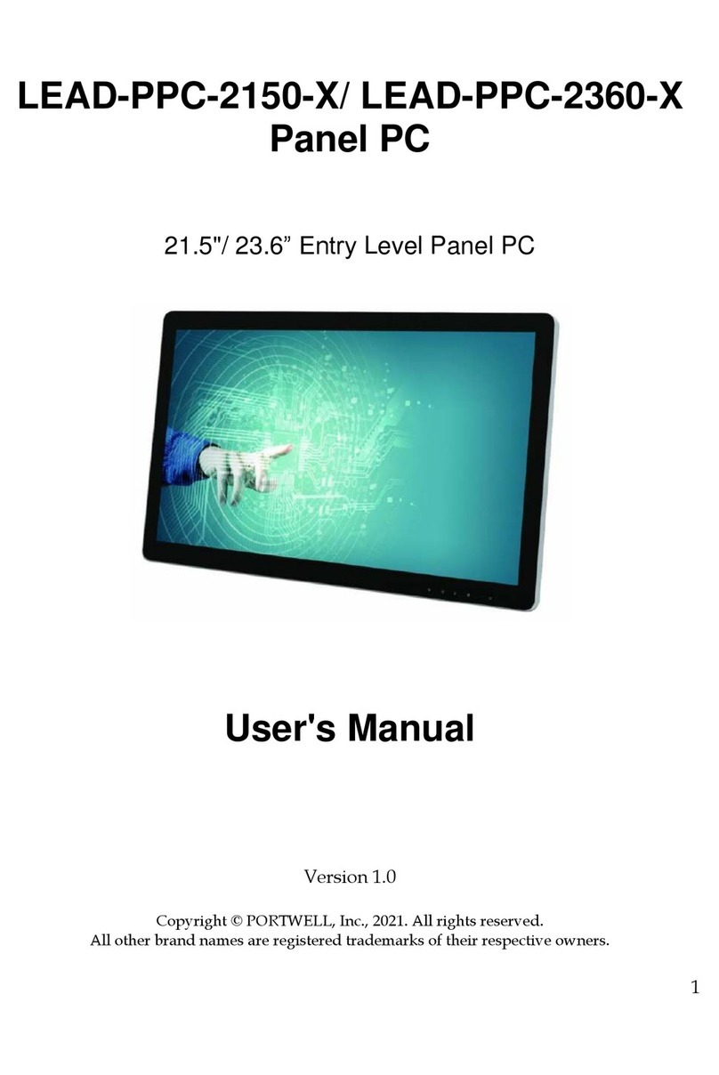
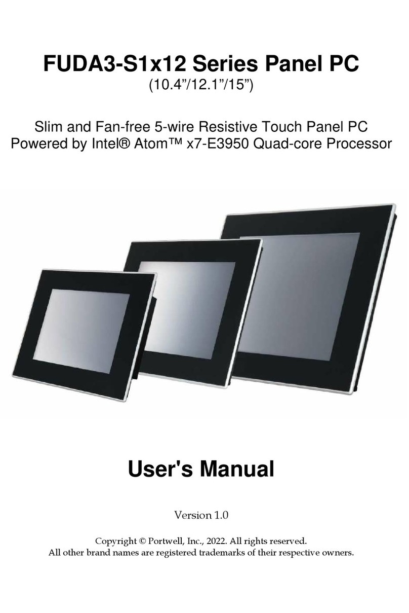
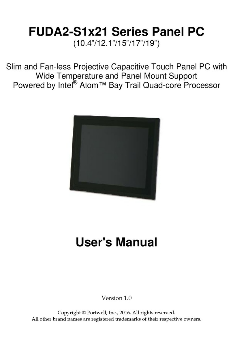
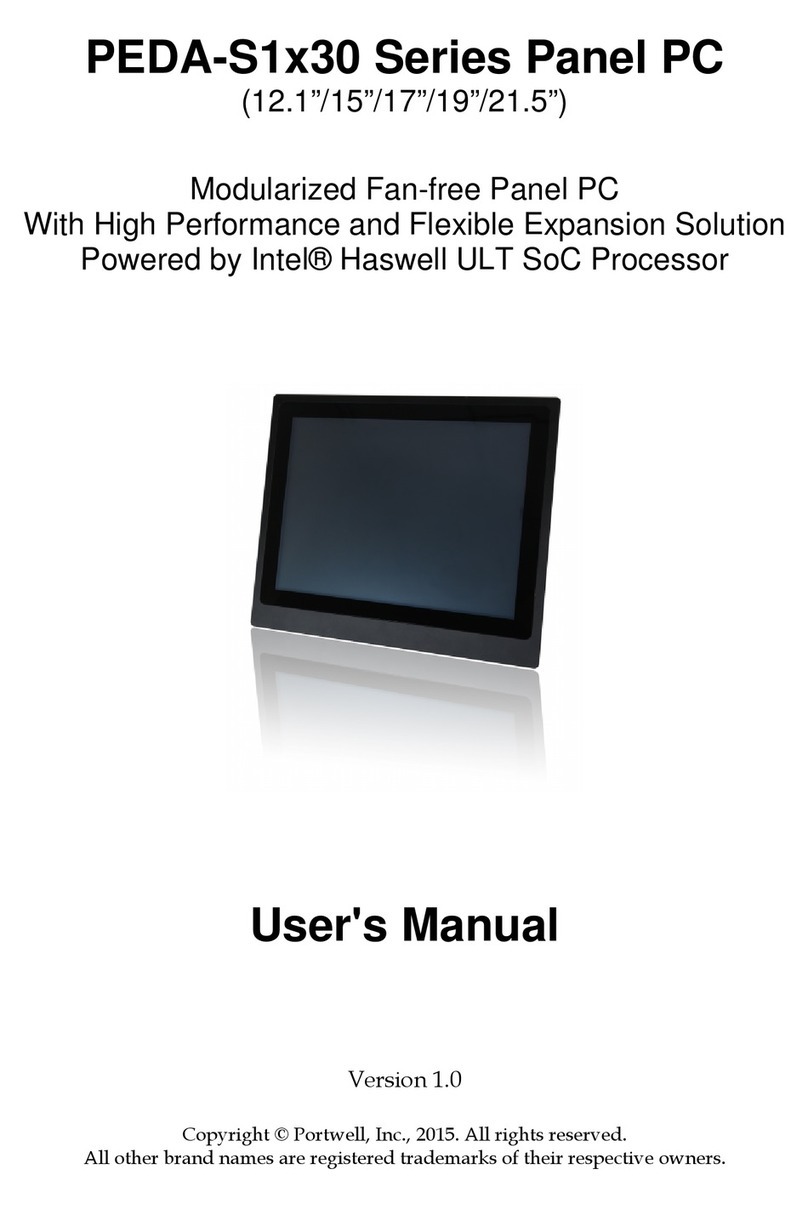
Portwell FUDA2-S1x11 Series User manual

FUDA2-S1x11 Series Panel PC
(10.4”/12.1”/15”/17”/19”)
Slim and Fan-free 5-wire Resistive Touch Panel PC
Powered by Intel® Atom™ Bay Trail Quad-core Processor
User's Manual
Version 1.1
Copyright © Portwell, Inc., 2015. All rights reserved.
All other brand na es are registered trade arks of their respective owners.

Preface
Table of Contents
How to Use This Manual
Chapter 1 System Overview.......................................................................................................1-1
1.1 Introduction ....................................................................................................... 1-1
1.2 Check List ........................................................................................................... 1-2
1.3 Product Specification ........................................................................................ 1-3
1.4 Mechanical Di ension ..................................................................................... 1-4
Chapter 2 System Installation....................................................................................................2-1
2.1 E bedded Board H/W Ju per Setting Introduction ................................. 2-1
2.2 Selectable I/O Kit Installation ......................................................................... 2-7
2.3 Me ory Installation ......................................................................................... 2-8
2.4 HDD Installation ............................................................................................... 2-9
2.5 CF and SD card Installation ............................................................................. 2-9
2.6 Getting Started ................................................................................................. 2-10
2.7 I/O Interfaces .................................................................................................. 2-10
2.7.1 Front View ............................................................................................... 2-10
2.7.2 Rear View ................................................................................................ 2-11
2.7.3 Top View ................................................................................................. 2-12
2.7.4 Side View ................................................................................................. 2-13
2.8 Mounting Method ........................................................................................... 2-13
2.8.1 Panel Mount ............................................................................................ 2-13
2.8.2 VESA® Mount ........................................................................................ 2-14
Chapter 3 Driver Installation and Touch Usage Guide............................................................3-1
3.1 Driver Installation ............................................................................................. 3-1
3.2 Calibration of the Touch Screen ...................................................................... 3-1
3.3 Light Sensor Function Setting ......................................................................... 3-3
Chapter 4 BIOS Setup Information............................................................................................4-1
4.1 Entering Setup—Launch Syste Setup ......................................................... 4-1
4.2 Main .................................................................................................................... 4-2
4.3 Configuration .................................................................................................... 4-3
4.4 Security ............................................................................................................. 4-20
4.5 Boot ................................................................................................................... 4-21
4.6 Save and Exit ................................................................................................... 4-23
Chapter 5 Important Instructions ..............................................................................................5-1
5.1 Note on the Warranty ....................................................................................... 5-1
5.2 Exclusion of Accident Liability Obligation ................................................... 5-1
5.3 Liability Li itations / Exe ption fro the Warranty Obligation............ 5-1
5.4 Declaration of Confor ity ............................................................................... 5-1
Chapter 6 Frequent Asked Questions.......................................................................................6-1

Preface
How to Use This Manual
The anual describes how to configure your FUDA2-S1x11 Series Panel PC syste to
eet various operating require ents. It is divided into four chapters, with each
chapter addressing a basic concept and operation of Fan-less Panel PC Syste .
Chapter 1: System Overview. Present what you have in the box and give you an
overview of the product specifications and basic architecture for Panel PC syste .
Chapter 2: System Installation. Show the definitions and locations of all the
interfaces and describe a proper installation guide so that you can easily configure
your syste .
Chapter 3: Driver Installation and Touch Usage Guide. Describe the operation
guide for included driver and software.
Chapter 4: BIOS Setup Information. Specify the eaning of each setup para eters,
how to get advanced BIOS perfor ance and update new BIOS. In addition, POST
checkpoint list will give users so e guidelines of trouble-shooting.
Chapter 5: Important Instructions. Indicate so e instructions which ust be
carefully followed when the Panel PC syste is used.
Chapter 6: Frequent Asked Questions. Provide the answers for the ost frequently
asked questions.
The content of this anual is subject to change without prior notice. These changes
will be incorporated in new editions of the docu ent. The vendor ay ake
supple ent or change in the products described in this docu ent at any ti e.
Revision History
Revision
Date Details of Change(s)
V1.0 2015/6/17
Initial Release
V1.1 2015/7/1 Add chapter of “E bedded Board H/W Ju per Setting
Introduction”

System Overview
FUDA2-S1x11 Series Panel PC User’s Manual 1-1
Chapter 1
System Overview
1.1 Introduction
FUDA2-S1x11 Series Panel PC is the next generation of Portwell’s standard Panel
PC product line. Keeping the successful experience in designing as well as arketing
its ascendant, FUDA-S1x10 Series Panel PC, in ind, FUDA2-S1x11 Series Panel PC
ai s at serving IPC custo ers with uch ore powerful HMI solutions which
provide high perfor ance and low power consu ption. Therefore, FUDA2-S1x11
Series Panel PC adopts the latest Intel Ato platfor , Bay Trail-I SoC processor
E3845 (10 W Max TDP, 2M Cache, 1.91 GHz).
The 4th generation Intel Ato Bay Trail-I series provides extended te perature
fro -40 to 110 degrees, high I/O connectivity, integrated e ory controller, error
correcting code (ECC), virtualization, and built-in security capabilities within 10W
ther al design power (TDP). A ong the , E3845 SoC processor is designed for
applications including highly efficient and dedicated i age signal processing with
secure content delivery, visually appealing HMI thin clients and obile HMI devices.
Equipped with a 5-wire resistive type touch screen and a panel with at least
resolution of 1024 x 768 pixels, it is housed in an Alu inu bezel with anodizing
coating that has a full IP65 rated front panel. This feature allows FUDA2-S1x11 Series
Panel PC to be used extensively in harsh environ ents such as the operating
te perature fro -20 to 70 ℃ degrees. The panel PC includes all required interfaces
for industrial application: 1 x DVI-I port, 2 x Gigabit Ethernet port, 3 x USB 1.1/2.0, 1
x USB 3.0, 2 x RS-232/422/485 port, 1 x 2.5" SATA HDD, 1x CF and 1 x SD socket for
storage capacity. One SMA Antenna holes provide optional wireless solution via half
size Mini-PCIe odule.
Further ore, facilitated with an a bient light sensor, FUDA2-S1x11 Series Panel
PC is capable of auto atically adjust panel brightness by sensing light intensity in the
surroundings, which allows the Panel PC to opti ize the display’s visibility in
se i-outdoor environ ents. Other than providing co fortable viewing experience,
this function also benefits FUDA2 Series by lowering the power consu ption and
extending the lifeti e of LED display.
To fulfill different application needs and to secure the syste fro power input
change, the syste accepts DC 12~24V wide range power input with 3-pin ter inal
block connector for various operating environ ent. The FUDA2-S1x11 Series Panel
PC offers panel ounting and equipped with standard 75 x75, 100 x 100 VESA
ounting holes. It supports any ainstrea operating syste s, such as Windows
8.1, Windows 7 and Linux.
System Overview
FUDA2-S1x11 Series Panel PC User’s Manual 1-2
1.2 Check List
The FUDA2-S1x11 Series Panel PC package covers the following ite s:
Essential
One FUDA2-S1x11 Panel PC
Panel Size Model Name
10.4” FUDA2-S1011
12.1” FUDA2-S1211
15” FUDA2-S1511
17” FUDA2-S1711
19” FUDA2-S1911
Panel Mount Kits
Panel Size Kits (pcs)
10.4” 8 pieces
12.1” 12 pieces
15” 16 pieces
17” 16 pieces
19” 20 pieces
Screws for HDD installation
M3X4L Screw 4 pieces
Driver CD
3-pin Ter inal Block Connector (Fe ale)
Optional
60W Power Adapter with Power Cord (EU/US type) and Switch Cable
60W P wer Adapter
P wer C rd (US type)
P wer C rd (EU type)
P wer Switch Cable (fr m DC Jack t 3-pin TBC)

System Overview
FUDA2-S1x11 Series Panel PC User’s Manual 1-3
Selectable I/O Kit
2x RS-232/422/485, 1x RS-232
(Expansi n: Opti n 1)
1x RS-232/422/485, 2x USB p rts and 1x Line- ut
(Expansi n: Opti n 2)
If any of these ite s is da aged or issing, please contact your vendor and keep all
packing aterials for future replace ent and aintenance.
1.3 Product Specification
Model Name
Model NameModel Name
Model Name
FUDA2
FUDA2FUDA2
FUDA2-
--
-S1011
S1011S1011
S1011
FUDA2
FUDA2FUDA2
FUDA2-
--
-S1211
S1211S1211
S1211
FUDA2
FUDA2FUDA2
FUDA2-
--
-S1511
S1511S1511
S1511
FUDA2
FUDA2FUDA2
FUDA2-
--
-S1
S1S1
S17
77
711
1111
11
FUDA2
FUDA2FUDA2
FUDA2-
--
-S1
S1S1
S19
99
911
1111
11
Display
DisplayDisplay
Display
LCD Size
LCD SizeLCD Size
LCD Size
10.4” 12.1 15” 17 19
Resolution
ResolutionResolution
Resolution
XGA 1024 x 768 XGA 1024 x 768 XGA 1024 x 768 SXGA 1280 x 1024 SXGA 1280 x 1024
Brightness
BrightnessBrightness
Brightness
450 cd/m
2
500 cd/m
2
450 cd/m
2
350 cd/m
2
350 cd/m
2
Contrast Ratio
Contrast RatioContrast Ratio
Contrast Ratio
3000:1 700:1 700:1 700:1 1000:1
Backlight
BacklightBacklight
Backlight
LED type LED type LED type LED type LED type
Touch Window
Touch WindowTouch Window
Touch Window
5-Wire Resistive Single Touch (P-CAP Touch by project)
System
SystemSystem
System
SOC
SOCSOC
SOC
Intel® Atom™ Qual-Core E3845 (1.91 GHz)
Memory
MemoryMemory
Memory
DDR3L SO-DIMM 1333/1600 MHz max up to 8 GB
BIOS
BIOSBIOS
BIOS
AMI
Graphics
GraphicsGraphics
Graphics
Intel® Gen7 Graphics
LVDS
LVDSLVDS
LVDS
Single/Dual Channel 24-bit
LAN Chipset
LAN ChipsetLAN Chipset
LAN Chipset
Dual Intel® I210IT Gigabit Ethernet (Support Jumbo Frame)
Aud
AudAud
Audio
ioio
io
Realtek High Definition Audio Codec
Watchdog Timer
Watchdog TimerWatchdog Timer
Watchdog Timer
1~255 levels reset
Storage Device
Storage DeviceStorage Device
Storage Device
2.5 SATA HDD / SSD, Compact Flash II up to 64 GB, SD card
OS
OSOS
OS
Windows 7 / Windows 8.1 / Linux™
I/O Interface
I/O InterfaceI/O Interface
I/O Interface
Series Port
Series PortSeries Port
Series Port
2 x RS-232/422/485 (Expansion : default)
Display
DisplayDisplay
Display
1 x DVI-I
USB
USBUSB
USB
1 x USB 2.0, 1 x USB 3.0, 2 x USB 2.0 (Expansion: default)
Ethernet
EthernetEthernet
Ethernet
2 x Gigabit Ethernet
Others
OthersOthers
Others
1 x SMA Antenna hole for WiFi/3G Solution
Expansion
ExpansionExpansion
Expansion
2 x RS-232/422/485, 1 x RS-232 (Expansion: option 1)
1 x Line-out, 1 x RS-232/422/485, 2 x USB 2.0 (Expansion: option 2)
Mechanical
MechanicalMechanical
Mechanical
Mounting (mm)
Mounting (mm)Mounting (mm)
Mounting (mm)
VESA Mount 75 x 75 & 100 x 100 ; Panel Mount
Weight (Kg)(N)
Weight (Kg)(N)Weight (Kg)(N)
Weight (Kg)(N)
3.5 Kg 4.3 Kg 5.3 Kg 6.8 Kg 7.8 Kg
Weight (Kg)(G)
Weight (Kg)(G)Weight (Kg)(G)
Weight (Kg)(G)
5.8 Kg 6.2 Kg 8.2 Kg 9.5 Kg 11.2 Kg
Dimension
DimensionDimension
Dimension
314 x 253 x 50.2 mm
343 x 282 x 53.2 mm
425.4 x 330 x 55.6 mm
437 x 375 x 58.6 mm
480 x 400 x 58.6 mm
Power
PowerPower
Power
Power Supply
Power SupplyPower Supply
Power Supply
DC 12 ~ 24V input with 3-pin Terminal Block Connector
Consumption (Max)
Consumption (Max)Consumption (Max)
Consumption (Max)
32W (12V); 35W (24V)
29W (12V); 30W (24V)
30W (12V); 31W (24V)
38W (12V); 38W (24V)
34W (12V); 34W (24V)
Consumption (Min)
Consumption (Min)Consumption (Min)
Consumption (Min)
10W (12V); 12W (24V)
Power Adaptor
Power AdaptorPower Adaptor
Power Adaptor
12V, 5A/60W(Optional)
Environmental
EnvironmentalEnvironmental
Environmental
OP /Storage Temp
OP /Storage TempOP /Storage Temp
OP /Storage Temp
-25~70 ℃ / -40~85℃(20~90% non-condensing)
Vibration
VibrationVibration
Vibration
1.0G (CF/SSD/SD) and 0.5G (HDD) , Power on & 2.16G, Packaged; 5~500Hz
Shock
ShockShock
Shock
15G peak acceleration, 11 ms (Power on condition)
Drop
DropDrop
Drop
Package with Carton from 96.5 cm (1-Corner, 3-Axis, 6-Face)
Front Panel Protection
Front Panel ProtectionFront Panel Protection
Front Panel Protection
IP65 (Front) / IP20 (Rear) (IEC 60529 Edition 2.1 Standard)
Certif
CertifCertif
Certification
icationication
ication
CE/FCC Class A

System Overview
FUDA2-S1x11 Series Panel PC User’s Manual 1-4
1.4 Mechanical Dimension
Front and side view of the FUDA2-S1011 syste
Back view of the FUDA2-S1011 syste

System Overview
FUDA2-S1x11 Series Panel PC User’s Manual 1-5
Front and side view of the FUDA2-S1211 syste
Back view of the FUDA2-S1211 syste

System Overview
FUDA2-S1x11 Series Panel PC User’s Manual 1-6
Front and side view of the FUDA2-S1511 syste
Back view of the FUDA2-S1511 syste

System Overview
FUDA2-S1x11 Series Panel PC User’s Manual 1-7
Front and side view of the FUDA2-S1711 syste
Back view of the FUDA2-S1711 syste

System Overview
FUDA2-S1x11 Series Panel PC User’s Manual 1-8
Front and side view of the FUDA2-S1911 syste
Back view of the FUDA2-S1911 syste

System Installation
FUDA2-S1x11 Series Panel PC User’s Manual 2-1
Chapter 2
System Installation
This chapter provides you with instructions to set up your FUDA2-S1x11 Series Panel
PC. Definitions and locations of all the interfaces are described so that you can easily
configure your syste .
2.1 Embedded Board H/W Jumper Setting Introduction
FUDA2-S1x11 Series Panel PC adopts PEB-99A4 other board. You ay configure
the Panel PC by setting ju pers of the other board to atch the needs of your
applications. To select any option, cover the ju per cap (SHORT) or re ove (NC) it
fro the ju per pins according to the following instructions.
*Note: NC stands for “Not Connect”.
Component side:

System Installation
FUDA2-S1x11 Series Panel PC User’s Manual 2-2
Solder side:
Connector and Jumper setting:
C nnect r
J2 Reserve f r CH7511 Backlight c ntr l.(Wafer/2.0mm)
J3 DDR3 SO-DIMM S cket.
J4 C mpact Flash c nnect r.
J5 PCI-E X 1 Sl t.
J6 Mini-PCI-E Sl t.(Half size)
J7 SATA C nnect r with p wer.
J8 GPIO C nnect r.(2*5 Pin/2.0mm)
J9 SM- Bus C nnect r.
J10 Battery C nnect r.
J11 PCI-E X4 Sl t(Right angle) f r Audi and COM P rt Signal .
J12 USB P rt 0~1 D-Sub C nnect r. (Up:USB2.0 D wn:USB3.0)
J13 RJ45 C nnect r.
J14 RJ45 C nnect r.
J15 DVI-I D-sub C nnect r.
J16 P wer Input C nnect r. (Terminal Bl cks 3Px1/5.08mm female)
J17 LCD Inverter P wer C nnect r. (1*5 Pin wafer/2mm)
J18 LCD LVDS C nnect r. (2*15 Pin Hir se/1.25mm)
J19 SD Card.
J20 Fr nt Panel C nnect r. (1*5 Pin Wafer/2mm)
J21 T uch Panel C nnect r. (1*5 Pin Header/2.54mm)
J22 USB P rt 3 C nnect r (1*4 Pin Wafer/2mm).
J23 Light sens r C nnect r (1*6 Pin Wafer/1mm).

System Installation
FUDA2-S1x11 Series Panel PC User’s Manual 2-3
Jumpers
JP1 Clear CMOS.
JP2 Backlight v ltage setup.
JP3 LCD Panel V ltage Setup.
JP4 LCD Panel Type Setup.
JP7 GPIO V ltage selecti n.
JP8 Audi ut.(Fr m amplifier)
JP9 LPC Debug P rt.
JP10 COM PORT RI and p wer s urce adjust pin.
JP11 COM PORT RI and p wer s urce adjust pin.
JP12 COM PORT RI and p wer s urce adjust pin.
JP13 COM PORT RI and p wer s urce adjust pin.
SW1 LCD Res luti n Setup
SW2 AT/ATX & BIOS rec very Setup.
J8: GPIO Connector (2*5 Pin Header/2 ):
PIN NO. DESCRIPTION PIN NO. DESCRIPTION
1 GPIO0 2 GPIO4
3 GPIO1 4 GPIO5
5 GPIO2 6 GPIO6
7 GPIO3 8 GPIO7
9 GND 10 +5V
J16: Power Input Connector (Ter inal Blocks 3Px1/5.08 fe ale)
PIN NO.
DESCRIPTION
1 GND EARTH
2 Vin-
3 Vin+
J17: LCD Inverter Power Connector (1*5 Pin wafer/2 )
PIN NO.
DESCRIPTION
1 LCD_ENBLT
2 GND
3 +12V
4 LCD_BLADJ
5 +5V
J18: LCD LVDS Connector (2*15 Pin Hirose/1.25 )
PIN NO.
Descripti n PIN NO.
Descripti n
1 YAP0 2 YAM0
3 YAP1 4 YAM1
5 YAP2 6 YAM2
7 YAP3 8 YAM3
9 CLKAP 10 CLKAM
11 YBP0 12 YBM0

System Installation
FUDA2-S1x11 Series Panel PC User’s Manual 2-4
13 YBP1 14 YBM1
15 YBP2 16 YBM2
17 YBP3 18 YBM3
19 CLKBP 20 CLKBM
21 DDCPCLK 22 DDCPDATA
23 GND 24 NC
25 GND 26 GND
27 +LVDS 28 +LVDS
29 NC 30 +LVDS
J20: Front Panel Connector (1*5 Pin Wafer/2 )
PIN NO.
DESCRIPTION
1 LED (Hi: Green LED +; L w: Orange LED -)
2 LED (Hi: Orange LED+; L w: Green LED-)
3 P wer Butt n
4 P wer Butt n
5 NC
J21: Touch Panel Connector (1*6 Pin Header/2.54 )
PIN NO.
DESCRIPTION
1 UL
2 UR
3 Pr be
4 LL
5 LR
J22: USB Port 3 Connector (1*5 Pin Wafer/2 )
PIN NO.
DESCRIPTION
1 + 5V
2 USB_D3-
3 USB_D3+
4 GND
JP1: CMOS Setup
PIN NO. DESCRIPTION
1-2 N rmal (Keep CMOS Setup) ★ Default
2-3 Clear CMOS Setup
JP2: LCD Panel Inverter ON/OFF Signal Setup
PIN NO. DESCRIPTION
1-3 2-4
Sh rt Sh rt +5V High Active ★ Default
PIN NO. DESCRIPTION
1-3 4-6
Sh rt Sh rt +12V High Active

System Installation
FUDA2-S1x11 Series Panel PC User’s Manual 2-5
PIN NO. DESCRIPTION
2-4 3-5
Sh rt Sh rt +5V L w Active
PIN NO. DESCRIPTION
3-5 4-6
Sh rt Sh rt +12V L w Active
JP3: LCD Panel Voltage Setup
PIN NO. DESCRIPTION
1-3 3-5 3-4 V ltage
Sh rt +3.3V TFT LCD ★ Default
Sh rt +5V TFT LCD
+12V TFT LCD
JP4: LCD Panel Type Setup
PIN NO. DESCRIPTION
1-3 3-5 2-4 4-6
Sh rt CCFL LCD
Sh rt LED LCD ★ Default
Sh rt CCFL LCD Brightness Limit
Sh rt LED LCD Brightness Limit
JP7: GPIO Power Selection
PIN NO. DESCRIPTION
1-2 5V Level ★ Default
2-3 3.3V Level
JP8: Internal Audio Connector
PIN NO. DESCRIPTION
1 Audi _R+
2 Audi _R-
3 Audi _L+
4 Audi _L-
JP9: LPC Debug Port Pin Assign ent
PIN NO. DESCRIPTION PIN NO. DESCRIPTION
1 LAD0 2 3.3V
3 LAD1 4 LPC_RESET
5 LAD2 6 LPC_FRAME
7 LAD3 8 LPC_CLCOK
10 GND

System Installation
FUDA2-S1x11 Series Panel PC User’s Manual 2-6
JP10: COM2 Pin 9 Function Setup
PIN NO. DESCRIPTION
1-2 3-4 5-6
Sh rt +5V Output
Sh rt RI Functi n ★ Default
Sh rt +12V Output
JP11: COM1 Pin 9 Function Setup
PIN NO. DESCRIPTION
1-2 3-4 5-6
Sh rt +5V Output
Sh rt RI Functi n ★ Default
Sh rt +12V Output
JP12: COM4 Pin 9 Function Setup
PIN NO. DESCRIPTION
1-2 3-4 5-6
Sh rt +5V Output
Sh rt RI Functi n ★ Default
Sh rt +12V Output
JP13: COM3 Pin 9 Function Setup
PIN NO. DESCRIPTION
1-2 3-4 5-6
Sh rt +5V Output
Sh rt RI Functi n ★ Default
Sh rt +12V Output
SW1: LCD Resolution Setup
PIN NO. Res luti n P rt
1 2 3 4
ON ON ON ON 800 x 600 (18bit) Single
OFF ON ON ON 1024 x768 (18bit)
Single
ON OFF ON ON 1024 x768 (24bit)
Single
OFF OFF ON ON 1280 x 768 (18bit)
Single
ON ON OFF ON 1280 x 800 (18bit)
Single
OFF ON OFF ON 1280 x 960 (18bit)
Single
ON OFF OFF ON 1280 x 1024 (24bit)
Dual
OFF OFF OFF ON 1366 x 768 (18bit)
Single
ON ON ON OFF 1366 x 768 (24bit)
Single
OFF ON ON OFF 1440 x 900 (24bit)
Dual
ON OFF ON OFF 1400 x 1050 (24bit)
Dual
OFF OFF ON OFF 1600 x 900 (24bit)
Dual

System Installation
FUDA2-S1x11 Series Panel PC User’s Manual 2-7
ON ON OFF OFF 1680 x 1050 (24bit)
Dual
OFF ON OFF OFF 1600 x 1200 (24bit)
Dual
ON OFF OFF OFF 1920 x 1080 (24bit)
Dual
OFF OFF OFF OFF 1920 x 1200 (24bit)
Dual
*Note: Default setting depends on the panel size.
*Note: Diagra of adjusting to resolution 800 x 600
SW2: AT/ATX & BIOS recovery Setup
PIN NO. DESCRIPTION
1-4(P rt1)
ON: AT M de
OFF:ATX M de ★ Default
2-3(P rt2)
ON: Rec ver BIOS
OFF: Disable ★ Default
*Note: Diagra of SW2 default setting
2.2 Selectable I/O Kit Installation
In addition to default I/O interfaces, including 1x DVI, 2x RS-232/422/485, 4x USB
and 2x Gigabit Ethernet, to further enhance syste flexibility as well as to increase
the versatility in application fields, FUDA2 Series allows users to select different I/O
co binations for various arket de ands.

System Installation
FUDA2-S1x11 Series Panel PC User’s Manual 2-8
1. Confir the position of Golden Finger
Connector
2.
Fix the I/O daughter board to the ain
board syste
2.3 Memory Installation
FUDA2 Series supports one DDR3L SO-DIMM e ory odule. It’s easy to install by
just opening the back cover.
1. Unscrew the back cover to detach it 2. Re ove the IPC back cover
3. Insert Me ory odule to the slot 4. Press down the e ory odule and
finish installation

System Installation
FUDA2-S1x11 Series Panel PC User’s Manual 2-9
2.4 HDD Installation
FUDA2 Series supports 1x 2.5” HDD/SSD. The unique design of the HDD tray
allows easy installation and aintenance. (The height ust be less than 10 )
1. Re ove the screws of HDD tray cover 2. Push the rod to release HDD tray
3. Install the HDD into tray with screws 4. Push HDD tray back into PPC
5. Screw the cover and finish installation 6. Inside view of installed HDD in PPC
2.5 CF and SD card Installation
CF and SD card are both supported in FUDA2 Series. It is easy to install CF and SD
card by opening the cover at side and insert the card.
1. CF cover locates at the right side.
Unscrew and re ove the side bracket.
2. Carefully insert CF and SD card into the
socket.
CF card SD card
3. Co plete insertion (Eject CF card by
pressing the elastic stick on the right side)
4. Screw the side bracket and finish
installation
CF card SD card
Table of contents
Other Portwell Touch Panel manuals

Portwell
Portwell LEAD-PND-2150 Series User manual

Portwell
Portwell EUDA 2 Series User manual

Portwell
Portwell FUDA3-S1 12 Series User manual

Portwell
Portwell PEDA S1x30 Series User manual

Portwell
Portwell AUDA-S08BS V3 User manual

Portwell
Portwell LEAD-PPC-2150-X User manual

Portwell
Portwell FUDA3-S1-22 Series User manual

Portwell
Portwell FUDA2-S1 21 Series User manual
Popular Touch Panel manuals by other brands

AMX
AMX Modero NXD-500i Operation/reference guide

ICOP Technology
ICOP Technology VOX-070-TS-EX2C8-V user manual

BOSER Technology
BOSER Technology BPF-3215-V user manual

Extron electronics
Extron electronics TLP Pro 1220MG Setup guide

Advantech
Advantech PPC-L126 user manual

Elo Touch Solutions
Elo Touch Solutions 17" X-Series user manual