Portwell FUDA2-S1 21 Series User manual

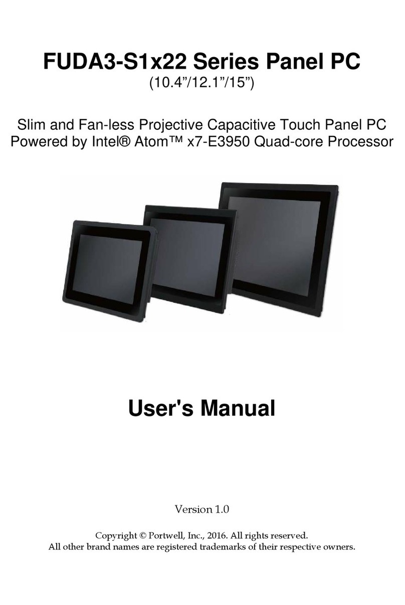
FUDA2-S1x21 Series Panel PC
(10.4”/12.1”/15”/17”/19”)
Slim and Fan-less Projective Capacitive Touch Panel PC with
Wide Temperature and Panel Mount Support
Powered by Intel®Atom™Bay Trail Quad-core Processor
User's Manual
Version 1.0
Copyright © Portwell, Inc., 2016. All rights reserved.
All other brand names are registered trademarks of their respective owners.

Preface
Table of Contents
How to Use This Manual
Chapter 1 System Overview.......................................................................................................1-1
1.1 Introduction.................................................................................................................................. 1-1
1.2 Check List ..................................................................................................................................... 1-2
1.3 Product Specification .................................................................................................................. 1-4
1.4 Mechanical Dimension................................................................................................................ 1-5
1.5 Safety Instruction....................................................................................................................... 1-10
1.5.1 Electrostatic Discharge (ESD) ........................................................................................ 1-11
1.5.2 Grounding Method ......................................................................................................... 1-11
1.5.3 Instructions for the Lithium Battery ............................................................................. 1-12
1.5.4 FCC Statement ................................................................................................................. 1-12
1.5.5 Electromagnetic Compatibility...................................................................................... 1-12
Chapter 2 System Installation....................................................................................................2-1
2.1 Embedded Board H/W Jumper Setting Introduction ............................................................ 2-1
2.1.1 Main Board......................................................................................................................... 2-1
2.1.2 Extension Board ................................................................................................................. 2-7
2.2 I/O Extension Kit Installation.................................................................................................. 2-10
2.3 Memory Installation.................................................................................................................. 2-11
2.4 HDD Installation........................................................................................................................ 2-11
2.5 Half-size mini PCIe module Installation ................................................................................ 2-12
2.6 CF and SD card Installation ..................................................................................................... 2-13
2.7 Getting Started ........................................................................................................................... 2-13
2.8 I/O Interfaces ............................................................................................................................. 2-14
2.8.1 Front View ........................................................................................................................ 2-14
2.8.2 Rear View ......................................................................................................................... 2-15
2.8.3 Top View........................................................................................................................... 2-16
2.8.4 Side View .......................................................................................................................... 2-17
2.9 Mounting Method ..................................................................................................................... 2-17
2.9.1 Panel Mount ..................................................................................................................... 2-17
2.9.2 VESA®Mount .................................................................................................................. 2-18
Chapter 3 Driver Installation and Touch Usage Guide............................................................3-1
3.1 Driver Installation........................................................................................................................ 3-1
3.2 Windows 7 Gesture for Multi-Touch Demand........................................................................ 3-1
Chapter 4 BIOS Setup Information............................................................................................4-1
4.1 Entering Setup—Launch System Setup.................................................................................... 4-1
4.2 Main............................................................................................................................................... 4-2
4.3 Configuration ............................................................................................................................... 4-3
4.4 Security ....................................................................................................................................... 4-20
4.5 Boot.............................................................................................................................................. 4-21
4.6 Save and Exit .............................................................................................................................. 4-23
Chapter 5 Important Instructions ..............................................................................................5-1
5.1 Note on the Warranty ................................................................................................................. 5-1
5.2 Exclusion of Accident Liability Obligation .............................................................................. 5-1
5.3 Liability Limitations / Exemption from the Warranty Obligation....................................... 5-1
5.4 Declaration of Conformity.......................................................................................................... 5-1
Chapter 6 Frequent Asked Questions.......................................................................................6-1

Preface
How to Use This Manual
The manual describes how to configure your FUDA2-S1x21 Series Panel PC system to
meet various operating requirements. It is divided into four chapters, with each
chapter addressing a basic concept and operation of Fan-less Panel PC System.
Chapter 1: System Overview. Present what you have in the box and give you an
overview of the product specifications and basic architecture for Panel PC system.
Chapter 2: System Installation. Show the definitions and locations of all the
interfaces and describe a proper installation guide so that you can easily configure
your system.
Chapter 3: Driver Installation and Touch Usage Guide. Describe the operation
guide for included driver and software.
Chapter 4: BIOS Setup Information. Specify the meaning of each setup parameters,
how to get advanced BIOS performance and update new BIOS. In addition, POST
checkpoint list will give users some guidelines of trouble-shooting.
Chapter 5: Important Instructions. Indicate some instructions which must be
carefully followed when the Panel PC system is used.
Chapter 6: Frequent Asked Questions. Provide the answers for the most frequently
asked questions.
The content of this manual is subject to change without prior notice. These changes
will be incorporated in new editions of the document. The vendor may make
supplement or change in the products described in this document at any time.
Portwell, Inc. clearly informs the users that this manual only encloses a general
description of technical processes and instructions which may not be applicable in
every single case. In cases of doubt, please contact Portwell, Inc.
© 2016 Portwell, Inc. All Rights Reserved.
Portwell, Inc.
http://www.portwell.com.tw
Address :No. 242, Bo-Ai Street, Shu-Lin District, New Taipei City, 238, Taiwan
TEL:+886-2-7731-8888 ;FAX:+886-2-7731-9888

Preface
Revision History
Revision
Date
Details of Change(s)
V1.0
2017/4/19
Initial Release

System Overview
FUDA2-S1x21 Series Panel PC User’s Manual 1-1
Chapter 1
System Overview
1.1 Introduction
Powered by Intel® Atom™ platform, Bay Trail-I SoC processor E3845, which
provides extended temperature and high I/O connectivity within 10W thermal
design power (TDP), FUDA2 Panel PC is an ideal platform for applications like
highly efficient and dedicated image signal processing with secure content delivery
and visually appealing HMI thin clients.
Equipped with a high resolution panel and a sleek, responsive, multi-touch screen,
FUDA2 Multi-Touch Panel PC comes with an IP65 rated front bezel and true-flat
design. This allows the system to be operated in harsh environment. With its refined
appearance, rugged mechanical chassis and multiple modular flexibility, FUDA2
Panel PC's application-oriented design provides customers an ideal HMI solution for
factory automation applications.
Thanks to its robustness and easy operation, Panel PC with projective capacitive
touch screen becomes a popular solution in the factory automation industry. With the
latest touch screen technology, FUDA2 Multi-Touch Panel PC Series is responsive
even when thick industrial gloves are worn and supports palm rejection. Moisture,
contaminant, and cutting oil are common in an industrial environment, so it is
important these materials don’t cause any false actions to the machine. Last but not
least, its excellent noise immunity makes it suitable in industrial application.
FUDA2 Panel PC features all required interfaces for industrial application: 12V ~
24V DC input, dual LAN, multiple USB ports and RS-232/422/485 selectable in BIOS
with auto-flow function. Different I/O extension kits can be chosen to serve different
market demand.

System Overview
FUDA2-S1x21 Series Panel PC User’s Manual 1-2
1.2 Check List
The FUDA2-S1x21 Series Panel PC package covers the following items:
Essential
One FUDA2-S1x21 Panel PC
Panel Size
Model Name
10.4”
FUDA2-S1021
12.1”
FUDA2-S1221
15”
FUDA2-S1521
17”
FUDA2-S1721
19”
FUDA2-S1921
Screws for HDD installation
M3X4L Screw 4 pieces
Driver CD
3-pin Terminal Block Connector (Female)
Optional
Panel Mount Kits
Panel Size
Kits (pcs)
10.4”
8 pieces
12.1”
8 pieces
15”
14 pieces
17”
16 pieces
19”
20 pieces
60W Power Adapter with Power Cord (EU/US type) and Switch Cable
60W Power Adapter
Power Cord (US type)
Power Cord (EU type)
Power Switch Cable (from DC Jack to 3-pin TBC)

System Overview
FUDA2-S1x21 Series Panel PC User’s Manual 1-3
I/O Extension Kit for FUDA2-S1021
2x RS-232/422/485
(Expansion: Option 0)
1x RS-232/422/485, 1x Line-out
(Expansion: Option 1)
2x USB 2.0, 1x Line-out
(Expansion: Option 2)
I/O Extension Kit for FUDA2-S12/15/17/1921
2x RS-232/422/485, 2x USB 2.0
(Expansion: Option 0)
2x RS-232/422/485, 1x RS-232
(Expansion: Option 1)
1x RS-232/422/485, 2x USB 2.0 and 1x Line-out
(Expansion: Option 2)
If any of these items is damaged or missing, please contact your vendor and keep all
packing materials for future replacement and maintenance.

System Overview
FUDA2-S1x21 Series Panel PC User’s Manual 1-4
1.3 Product Specification
Model Name
FUDA2-S1021
FUDA2-S1221
FUDA2-S1521
FUDA2-S1721
FUDA2-S1921
Display
LCD Size
10.4”
12.1"
15”
17"
19"
Resolution
XGA 1024 x 768
XGA 1024 x 768
XGA 1024 x 768
SXGA 1280 x 1024
SXGA 1280 x 1024
Brightness
450 cd/m2
600 cd/m2
450 cd/m2
350 cd/m2
350 cd/m2
Contrast Ratio
3000:1
700:1
700:1
1000:1
1000:1
Backlight
LED type
LED type
LED type
LED type
LED type
Touch Window
Projective Capacitive Multi-Touch (10 points)
System
SOC
Intel®Atom™ Quad-Core E3845 (1.91 GHz)
Memory
DDR3L SO-DIMM 1333/1600 MHz max up to 8 GB
BIOS
AMI
Graphics
Intel® Gen7 Graphics
LVDS
Single/Dual Channel 24-bit
LAN Chipset
Dual Intel®I210IT Gigabit Ethernet (Support Jumbo Frame)
Audio
Realtek®High Definition Audio Codec
Watchdog Timer
Programmable 1~255 secs
Storage Device
2.5" SATA HDD / SSD, Compact Flash II up to 64 GB, SD card
OS
Windows 7 / Windows 8.1 / Windows 10 / Linux™
I/O Interface
Series Port
2 x RS-232/422/485 (Expansion : Option 0)
Display
1 x DVI-I
USB
1 x USB 2.0, 1 x USB 3.0
1 x USB 2.0, 1 x USB 3.0, 2 x USB 2.0 (Expansion: Option 0)
Ethernet
2 x Gigabit Ethernet
Others
1 x SMA Antenna hole for WiFi/3G Solution
Expansion
1 x Half mPCIe socket
1 x RS-232/422/485, 1
x Line-out (Option 1)
1 x Half-size Mini PCIe socket
2 x RS-232/422/485, 1 x RS-232 (Expansion: Option 1)
1 x Line-out, 1 x RS-232/422/485, 2 x USB 2.0 (Expansion: Option 2)
1 x Line-out, 2 x USB
2.0 (Option 2)
Mechanical
Mounting (mm)
VESA Mount 75 x 75 & 100 x 100 ; Panel Mount
Weight (Kg)(N)
3.5 Kg
3.9 Kg
5.1 Kg
6.5 Kg
7.6 Kg
Weight (Kg)(G)
5.8 Kg
6 Kg
7.8 Kg
9.8 Kg
11.5 Kg
Dimension
282 x 238 x 57.3 mm
305 x 260 x 58.2 mm
384 x 310 x 56.6 mm
437 x 375 x 63.2 mm
480 x 400 x 60.4 mm
Power
Power Supply
DC 12 ~ 24V input with 3-pin Terminal Block Connector
Consumption (Max)
41W (12V); 40W (24V)
34W (12V); 34W (24V)
39W (12V); 38W (24V)
47W (12V); 46W (24V)
40W (12V); 42W (24V)
Consumption (Min)
15W (12V); 16W (24V)
13W (12V); 14W (24V)
16W (12V); 17W (24V)
14W (12V); 15W (24V)
20W (12V); 21W (24V)
Power Adaptor
12V, 5A/60W(Optional)
Environmental
OP /Storage Temp
-25~70 ℃/ -40~85℃(20~90% non-condensing)
Vibration
1.0G (CF/SSD/SD) and 0.5G (HDD) , Power on & 2.16G, Packaged; 5~500Hz, IEC 60068-2-6
Shock
15G peak acceleration, 11 ms (Power on condition), IEC 60068-2-27
Drop
Package with Carton from 96.5 cm (1-Corner, 3-Axis, 6-Face), ISTA 2A Standard
Front Panel Protection
IP65 (Front) / IP20 (Rear), IEC 60529 Edition 2.1 Standard
Certification
CE/FCC Class A
Pollution Degree
2

System Overview
FUDA2-S1x21 Series Panel PC User’s Manual 1-5
1.4 Mechanical Dimension
Front and side view of the FUDA2-S1021 system
Back view of the FUDA2-S1021 system

System Overview
FUDA2-S1x21 Series Panel PC User’s Manual 1-6
Front and side view of the FUDA2-S1221 system
Back view of the FUDA2-S1221 system

System Overview
FUDA2-S1x21 Series Panel PC User’s Manual 1-7
Front and side view of the FUDA2-S1521 system
Back view of the FUDA2-S1521 system

System Overview
FUDA2-S1x21 Series Panel PC User’s Manual 1-8
Front and side view of the FUDA2-S1721 system
Back view of the FUDA2-S1721 system

System Overview
FUDA2-S1x21 Series Panel PC User’s Manual 1-9
Front and side view of the FUDA2-S1921 system
Back view of the FUDA2-S1921 system

System Overview
FUDA2-S1x21 Series Panel PC User’s Manual 1-10
1.5 Safety Instruction
Caution:
This section should be carefully read and please abide by the instructions for
your own safety and correct use of the unit.
The chapter also includes information on approval and interference inhibition of your
unit. Please abide by the warnings and instructions on the unit and in the manual.
The FUDA2-S1x21 Series Panel PC was built and tested by Portwell, Inc. in
accordance with and kept the company within under perfectly safe condition.
In order to retain this condition and ensure safe operation, the users must abide by
the instructions and warnings
The unit must be used in accordance with the instructions of usage.
The electrical installations in the room must not violate the requirements of the
local (country-specific) regulations.
Pay careful attention that there are no cables, especially power cables, in areas that
people can go over them.
Only use the power cord supplied as specification. Don’t use damaged power
cords.
Hints for DC power connection: The DC power source should be able to be switched
off and on via an isolating switch. The unit is only completely disconnected from the
DC main power source when the DC power cord is disconnected either from the
power source or the unit. Therefore, the DC power cord and its connectors must
always remain within reach. The Power source should be SELV or from the
secondary circuits are circuits where separation from MAINS CIRCUITS is achieved
by a transformer in which the primary windings are separated from the secondary
windings by REINFORCED INSULATION, DOUBLE INSULATION, or a screen
connected to the PROTECTIVE CONDUCTOR TERMINAL
Hints for AC power connection via external AC/DC adapter: The main power cable
of the optional external AC/DC adapter serves as disconnecting device. For this
reason the outlet of the AC power source must be located near to the device and easy
to reach.
Never place the unit under direct sunlight, near heat sources or in a humid place.
Make sure the unit has proper ventilation.
All plugs on the connection cables must be screwed or locked to the housing.
FUDA2-S1x21 Series Panel PC is designed to be used on the desk or upright with
the I/O interfaces downwards.
The unit generates heat under operation condition. Make sure it is properly
ventilated. Never cover up the air intake and exhaust openings of the unit. Do not
impede the fins of the heat sink.
Be aware of the warm surface of heat sink at back side. A protective wear is
recommended.

System Overview
FUDA2-S1x21 Series Panel PC User’s Manual 1-11
Repairs may only be operated by specialists or technicians qualified and
authorized by Portwell, Inc.
Maintenance or repair on the open unit may only be operated by specialists or
technicians qualified and authorized by Portwell, Inc. and familiar with the
related hazards.
When accessing internal components, users must switch off the unit and
disconnect it from the power source.
Only original accessories (or suggested optional parts) approved and supplied by
Portwell, Inc. may be used.
The installation that the safety of any system incorporating the equipment is the
responsibility of the assembler of the system.
If the equipment is used in a manner not specified by the manufacturer, the
protection provided by the equipment may be impaired.
Assumption of safe operation no longer possible must be taken,
- if the unit has obvious damage or
- if the unit no longer functions.
Under such cases, the unit must be shut down and secured against any
unintended operation.
1.5.1 Electrostatic Discharge (ESD)
A sudden discharge of electrostatic electricity can damage electrostatic-sensitive
devices or circuits. Adequate packaging and grounding techniques are essential to
avoid damage. Following precautions should be taken:
1. Deliver printed circuit boards in electrostatic-safe containers such as cartons,
boxes or anti-static bags.
2. Keep electrostatic-sensitive parts in their containers until they reach an
electrostatic-free station.
3. Follow adequate grounding when a sensitive PCB, components, or assemblies are
touched.
4. Store electrostatic-sensitive PCB’s in a protective packaging or on conductive
foam.
1.5.2 Grounding Method
Protect against electrostatic damage of the unit by taking the following preventative
measures:
1. Cover workstations with approved anti-electrostatic material. Provide a wrist
strap connected to a working bench and properly grounded tools and equipment.
2. For extra protection use anti-electrostatic mats, heel straps, or air ionizers.
3. Handle electrostatic-sensitive components, PCBs, and assemblies with care
nearby the case or the edge of the board.
4. Prevent contact with pins, leads, or circuitry.
5. Switch off power and input signals before plugging and removing connectors or
test equipment.

System Overview
FUDA2-S1x21 Series Panel PC User’s Manual 1-12
6. Keep the work area free from non-conductive materials such as ordinary plastic
assembly aids and Styrofoam.
7. Use field service tools with conductivity, such as screwdrivers, pliers, and
vacuum cleaners.
8. Always put drives and PCBs with the component-side down on the working
bench.
1.5.3 Instructions for the Lithium Battery
Caution:
Please contact. Portwell, Inc directly. Prohibit replace by user
Do not throw away used CMOS batteries to domestic waste. Throw away the
battery according to the local regulations pertaining to the disposal of these
special materials (e. g. to the collecting points for disposal of batteries).
1.5.4 FCC Statement
This equipment has been tested and found to comply with the limits for a Class A
digital device, pursuant to Part 15B of the FCC Rules. These limits are designed to
provide reasonable protection from harmful interference when the equipment is
operated in a commercial environment. This equipment generates, uses, and can
radiate radio frequency energy and, if not installed and used in accordance with the
instruction manual, may cause harmful interference to radio communications.
Operation of this equipment in residential areas is likely to cause harmful
interference in which case the users will be required to correct the interference at
his/her own expense.
1.5.5 Electromagnetic Compatibility
The system has been designed for industrial use. The most recent version of the EMC
guidelines (EMC Directive 2014/30/EU) is applied following standards, EN 55011/
EN 61000-6-4 / EN 61000-6-2 and EN 55032 / EN 55024. If users modify and/or add
device to the equipment (e.g. installation of add-on cards), the prerequisite for the CE
conformity declaration (safety requirement) may not be applicable anymore.

System Installation
FUDA2-S1x21 Series Panel PC User’s Manual 2-1
Chapter 2
System Installation
This chapter provides you with instructions to set up your FUDA2-S1x21 Series Panel
PC. Definitions and locations of all the interfaces are described so that you can easily
configure your system.
2.1 Embedded Board H/W Jumper Setting Introduction
2.1.1 Main Board
FUDA2-S1x21 Series Panel PC adopts PEB-99A4 mother board. You may configure
the Panel PC by setting jumpers of the mother board to match the needs of your
applications. To select any option, cover the jumper cap (SHORT) or remove (NC) it
from the jumper pins according to the following instructions.
*Note: NC stands for “Not Connect”.
Component side:

System Installation
FUDA2-S1x21 Series Panel PC User’s Manual 2-2
Solder side:
Connector and Jumper setting:
Connector
J2
Reserve for CH7511 Backlight control.(Wafer/2.0mm)
J3
DDR3 SO-DIMM Socket.
J4
Compact Flash connector.
J5
PCI-E X 1 Slot.
J6
Mini-PCI-E Slot.(Half size)
J7
SATA Connector with power.
J8
GPIO Connector.(2*5 Pin/2.0mm)
J9
SM- Bus Connector.
J10
Battery Connector.
J11
PCI-E X4 Slot(Right angle) for Audio and COM Port Signal .
J12
USB Port 0~1 D-Sub Connector. (Up:USB2.0 Down:USB3.0)
J13
RJ45 Connector.
J14
RJ45 Connector.
J15
DVI-I D-sub Connector.
J16
Power Input Connector. (Terminal Blocks 3Px1/5.08mm female)
J17
LCD Inverter Power Connector. (1*5 Pin wafer/2mm)
J18
LCD LVDS Connector. (2*15 Pin Hirose/1.25mm)
J19
SD Card.
J20
Front Panel Connector. (1*5 Pin Wafer/2mm)
J21
Touch Panel Connector. (1*5 Pin Header/2.54mm)
J22
USB Port 3 Connector (1*4 Pin Wafer/2mm).
J23
Light sensor Connector (1*6 Pin Wafer/1mm).

System Installation
FUDA2-S1x21 Series Panel PC User’s Manual 2-3
Jumpers
JP1
Clear CMOS.
JP2
Backlight voltage setup.
JP3
LCD Panel Voltage Setup.
JP4
LCD Panel Type Setup.
JP7
GPIO Voltage selection.
JP8
Audio out.(From amplifier)
JP9
LPC Debug Port.
JP10
COM2 PORT RI and power source adjust pin.
JP11
COM1 PORT RI and power source adjust pin.
JP12
COM4 PORT RI and power source adjust pin.
JP13
COM3 PORT RI and power source adjust pin.
SW1
LCD Resolution Setup
SW2
AT/ATX & BIOS recovery Setup.
J8: GPIO Connector (2*5 Pin Header/2mm):
PIN NO.
DESCRIPTION
PIN NO.
DESCRIPTION
1
GPIO0
2
GPIO4
3
GPIO1
4
GPIO5
5
GPIO2
6
GPIO6
7
GPIO3
8
GPIO7
9
GND
10
+5V
J16: Power Input Connector (Terminal Blocks 3Px1/5.08mm female)
PIN NO.
DESCRIPTION
1
Functional GND
2
Vin-
3
Vin+
J17: LCD Inverter Power Connector (1*5 Pin wafer/2mm)
PIN NO.
DESCRIPTION
1
LCD_ENBLT
2
GND
3
+12V
4
LCD_BLADJ
5
+5V
J18: LCD LVDS Connector (2*15 Pin Hirose/1.25mm)
PIN NO.
Description
PIN NO.
Description
1
YAP0
2
YAM0
3
YAP1
4
YAM1
5
YAP2
6
YAM2
7
YAP3
8
YAM3
9
CLKAP
10
CLKAM
11
YBP0
12
YBM0

System Installation
FUDA2-S1x21 Series Panel PC User’s Manual 2-4
13
YBP1
14
YBM1
15
YBP2
16
YBM2
17
YBP3
18
YBM3
19
CLKBP
20
CLKBM
21
DDCPCLK
22
DDCPDATA
23
GND
24
NC
25
GND
26
GND
27
+LVDS
28
+LVDS
29
NC
30
+LVDS
J20: Front Panel Connector (1*5 Pin Wafer/2mm)
PIN NO.
DESCRIPTION
1
LED (Hi: Green LED +; Low: Orange LED -)
2
LED (Hi: Orange LED+; Low: Green LED-)
3
Power Button
4
Power Button
5
NC
J21: Touch Panel Connector (1*6 Pin Header/2.54mm)
PIN NO.
DESCRIPTION
1
UL
2
UR
3
Probe
4
LL
5
LR
J22: USB Port 3 Connector (1*5 Pin Wafer/2mm)
PIN NO.
DESCRIPTION
1
+ 5V
2
USB_D3-
3
USB_D3+
4
GND
JP1: CMOS Setup
PIN NO.
DESCRIPTION
1-2
Normal (Keep CMOS Setup) ★Default
2-3
Clear CMOS Setup
JP2: LCD Panel Inverter ON/OFF Signal Setup
PIN NO.
DESCRIPTION
1-3
2-4
Short
Short
+5V High Active ★Default
PIN NO.
DESCRIPTION
1-3
4-6
Short
Short
+12V High Active
This manual suits for next models
5
Table of contents
Other Portwell Touch Panel manuals

Portwell
Portwell PEDA S1x30 Series User manual

Portwell
Portwell AUDA-S08BS V3 User manual

Portwell
Portwell FUDA2-S1x11 Series User manual

Portwell
Portwell LEAD-PPC-2150-X User manual

Portwell
Portwell FUDA3-S1-22 Series User manual

Portwell
Portwell LEAD-PND-2150 Series User manual

Portwell
Portwell EUDA 2 Series User manual

Portwell
Portwell FUDA3-S1 12 Series User manual