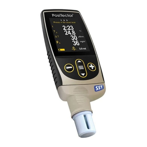
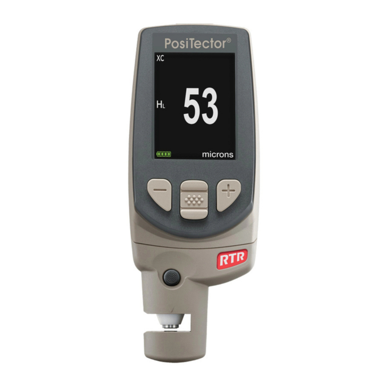
POSITECTOR SHD Verifier User manual

Instruction Manual v. 1.0
Returning for Service
If you need to return the PosiTector SHD Verifier for service, describe the
problem fully and include reading results, if any. Be sure to include contact
information including your company name, company contact, telephone
number and fax number or email address. defelsko.com/support
The PosiTector SHD Verifier kit is ideal for checking the accuracy and
operation of shore hardness durometers and is an important component
in fulfilling both ISO and in-house quality control requirements.
The kit is ready to use with all PosiTector SHD Shore Hardness
Durometers. The Smart Sensor Indicator (SSI) has been preset, and no
additional configuration is required or recommended. If the SSI settings
are mistakenly altered, see Reconfiguring the SSI Device (pg. 3).
Range: 0 - 10 lbs
Resolution: 0.001 lbs
Accuracy: +0.004 lbs (+17.8 mN)
NOTE: Device displays imperial units only.
4
Introduction
Introduction
Technical Data
Technical Data
Load
Cell
Smart Sensor Indicator (SSI)
Load Cell Cable
Limited Warranty, Sole Remedy and Limited Liability
DeFelsko's sole warranty, remedy, and liability are the express limited
warranty, remedy, and limited liability that are set forth on its website:
www.defelsko.com/terms.
www.defelsko.com
© DeFelsko Corporation USA 2017. All Rights Reserved
This manual is copyrighted with all rights reserved and may not be
reproduced or transmitted, in whole or part, by any means, without
written permission from DeFelsko Corporation.
DeFelsko and PosiTector are trademarks of DeFelsko Corporation
registered in the U.S. and in other countries. Other brand or product
names are trademarks or registered trademarks of their respective
holders.
Every effort has been made to ensure that the information in this manual
is accurate. DeFelsko is not responsible for printing or clerical errors.
Verifier
DEVICE COMES COMPLETE
with load cell, smart sensor indicator,
built-in rechargeable Lithium Ion
batteries with universal AC adaptor,
replaceable Shore A (aluminum) and
Shore D (brass) targets, allen wrench,
instructions, Sample Certificate of
Accuracy, hard shell carrying case,
two Certificates of Calibration
traceable to NIST, one (1) year
warranty.
www. .com information@itm.com1.800.561.8187

1. Remove the PosiTector SHD Verifier
and Smart Sensor Indicator from the case.
Make sure to place the PosiTector SHD
Verifier on a stable flat surface.
2. Connect the Load Cell Cable to
the Smart Sensor Indicator
The PosiTector SHD Verifier includes Certificates of Calibration for the SSI
and load cell. For information on returning your PosiTector SHD Verifier for
recertification, contact DeFelsko or your local dealer.
The PosiTector SHD Verifier, with valid Certificates of Calibration, can be
used to check the accuracy of PosiTector SHD Shore Hardness
Durometers. A sample Certificate of Accuracy is included.
The SSI device comes pre-configured for verification of PosiTector SHD
Shore Hardness Durometers. No additional configuration is required or
recommended.
If the SSI is mistakenly altered, configuration can be restored by following
the steps outlined in our Reconfiguration Guide. Contact DeFelsko for more
information.
2 3
PosiTector SHD Verifier Set-up
Reconfiguring the SSI Device
Certification
Certification
3. Select a SHD A (aluminum) or SHD D (brass) target and insert it into
the load cell as shown. Note: Inspect the targets before installing. To
prevent damage to the PosiTector SHD D probe tip, the SHD D (brass)
target is designed to be dented during testing and will periodically need to
be replaced. The SHD A (aluminum) target will not be dented during testing
and should be replaced if there is any damage to the top surface.
4.1 Perform a Gage Reset on the PosiTector SHD
4.2 Select Continuous Reading Mode from the Setup menu on the
PosiTector SHD.
4.3 Turn the Micrometer Adjustment so that it is set between 1 and 2.
4.4 Place the PosiTector SHD probe into Probe Holder. Ensure that the
probe tip doesn’t touch the target.
For detailed instructions see the PosiTector SHD Calibration Procedure
Shore A 10 20 30 40 50 60 70 80 90
SHD Verifier
Displays (lbs) 0.292 0.461 0.629 0.798 0.967 1.135 1.304 1.472 1.641
Shore D 10 20 30 40 50 60 70 80 90
SHD Verifier
Displays (lbs) 0.999 1.999 2.998 3.997 4.996 5.996 6.995 7.994 8.994
4.5 Power on the Smart Sensor Indicator
4.6 Turn the Micrometer Adjustment to lower the probe onto the target until
the desired load is displayed on the SHD Verifier corresponding to the
Shore A or Shore D verification points illustrated below.
4.7 Verify that the PosiTector SHD is reading within + 1 Shore value of
the corresponding load.
Repeat steps 4.6 – 4.7 for each verification point.
Quick Calibration Procedure
SHD
Target
Probe
Holder
Target Micrometer
Adjustment
www. .com information@itm.com1.800.561.8187

1. Remove the PosiTector SHD Verifier
and Smart Sensor Indicator from the case.
Make sure to place the PosiTector SHD
Verifier on a stable flat surface.
2. Connect the Load Cell Cable to
the Smart Sensor Indicator
The PosiTector SHD Verifier includes Certificates of Calibration for the SSI
and load cell. For information on returning your PosiTector SHD Verifier for
recertification, contact DeFelsko or your local dealer.
The PosiTector SHD Verifier, with valid Certificates of Calibration, can be
used to check the accuracy of PosiTector SHD Shore Hardness
Durometers. A sample Certificate of Accuracy is included.
The SSI device comes pre-configured for verification of PosiTector SHD
Shore Hardness Durometers. No additional configuration is required or
recommended.
If the SSI is mistakenly altered, configuration can be restored by following
the steps outlined in our Reconfiguration Guide. Contact DeFelsko for more
information.
2 3
PosiTector SHD Verifier Set-up
Reconfiguring the SSI Device
Certification
Certification
3. Select a SHD A (aluminum) or SHD D (brass) target and insert it into
the load cell as shown. Note: Inspect the targets before installing. To
prevent damage to the PosiTector SHD D probe tip, the SHD D (brass)
target is designed to be dented during testing and will periodically need to
be replaced. The SHD A (aluminum) target will not be dented during testing
and should be replaced if there is any damage to the top surface.
4.1 Perform a Gage Reset on the PosiTector SHD
4.2 Select Continuous Reading Mode from the Setup menu on the
PosiTector SHD.
4.3 Turn the Micrometer Adjustment so that it is set between 1 and 2.
4.4 Place the PosiTector SHD probe into Probe Holder. Ensure that the
probe tip doesn’t touch the target.
For detailed instructions see the PosiTector SHD Calibration Procedure
at dl.defelsko.com/pdf/manuals/PosiTectorSHD-Verifier-v1.0.pdf
Shore A 10 20 30 40 50 60 70 80 90
SHD Verifier
Displays (lbs) 0.292 0.461 0.629 0.798 0.967 1.135 1.304 1.472 1.641
Shore D 10 20 30 40 50 60 70 80 90
SHD Verifier
Displays (lbs) 0.999 1.999 2.998 3.997 4.996 5.996 6.995 7.994 8.994
4.5 Power on the Smart Sensor Indicator
4.6 Turn the Micrometer Adjustment to lower the probe onto the target until
the desired load is displayed on the SHD Verifier corresponding to the
Shore A or Shore D verification points illustrated below.
4.7 Verify that the PosiTector SHD is reading within + 1 Shore value of
the corresponding load.
Repeat steps 4.6 – 4.7 for each verification point.
Quick Calibration Procedure
SHD
Target
Probe
Holder
Target Micrometer
Adjustment
www. .com information@itm.com1.800.561.8187

Instruction Manual v. 1.0
Returning for Service
If you need to return the PosiTector SHD Verifier for service, describe the
problem fully and include reading results, if any. Be sure to include contact
information including your company name, company contact, telephone
The PosiTector SHD Verifier kit is ideal for checking the accuracy and
operation of shore hardness durometers and is an important component
in fulfilling both ISO and in-house quality control requirements.
The kit is ready to use with all PosiTector SHD Shore Hardness
Durometers. The Smart Sensor Indicator (SSI) has been preset, and no
additional configuration is required or recommended. If the SSI settings
are mistakenly altered, see Reconfiguring the SSI Device (pg. 3).
Range: 0 - 10 lbs
Resolution: 0.001 lbs
Accuracy: +0.004 lbs (+17.8 mN)
NOTE: Device displays imperial units only.
4
Introduction
Introduction
Technical Data
Technical Data
Load
Cell
Smart Sensor Indicator (SSI)
Load Cell Cable
Limited Warranty, Sole Remedy and Limited Liability
DeFelsko's sole warranty, remedy, and liability are the express limited
warranty, remedy, and limited liability that are set forth on its website:
© DeFelsko Corporation USA 2017. All Rights Reserved
This manual is copyrighted with all rights reserved and may not be
reproduced or transmitted, in whole or part, by any means, without
written permission from DeFelsko Corporation.
DeFelsko and PosiTector are trademarks of DeFelsko Corporation
registered in the U.S. and in other countries. Other brand or product
names are trademarks or registered trademarks of their respective
holders.
Every effort has been made to ensure that the information in this manual
is accurate. DeFelsko is not responsible for printing or clerical errors.
Verifier
DEVICE COMES COMPLETE
with load cell, smart sensor indicator,
built-in rechargeable Lithium Ion
batteries with universal AC adaptor,
replaceable Shore A (aluminum) and
Shore D (brass) targets, allen wrench,
instructions, Sample Certificate of
Accuracy, hard shell carrying case,
two Certificates of Calibration
traceable to NIST, one (1) year
warranty.
www. .com information@itm.com1.800.561.8187
Table of contents
Other POSITECTOR Test Equipment manuals