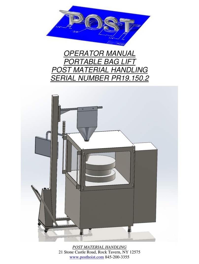
Post PR21.43 User manual

POST MATERIAL HANDLING
21 Stone Castle Road, Rock Tavern, NY 12575
www.posthoist.com 845-200-3355
TABLE OF CONTENTS
TABLE OF CONTENTS.................................................................................................................................... 2
INTRODUCTION .............................................................................................................................................. 3
DESCRIPTION................................................................................................................................................... 3
PRINCIPLE OF OPERATION........................................................................................................................... 3
GENERAL SPECIFICATIONS.......................................................................................................................... 4
LIFT OPERATION............................................................................................................................................. 4
MANUAL CONTROL MODE OF OPERATION (Maintenance only)............................................................. 4
TEACH MODE OF OPERATION TO SET POSITIONS (Maintenance only)................................................. 5
EMERGENCY STOP......................................................................................................................................... 6
SAFETY ............................................................................................................................................................. 6
INSTALLATION INSTRUCTIONS .................................................................................................................. 6
MAINTENANCE ............................................................................................................................................. 10
STATUS INDICATOR LIGHT......................................................................................................................... 10
REMOVING THE INVERSION ACCESS COVER ........................................................................................11
GAIN ACCESS TO THE INVERSION COMPONENTS............................................................................... 12
CLEANING PROCEDURES........................................................................................................................... 13
SLOT COVER AND SHROUD REMOVAL................................................................................................... 13
POWER DISCONNECT .................................................................................................................................. 13
DISCHARGE VALVE AND ACTUATOR REMOVAL .................................................................................. 13
CHECK LIFT CHAIN TENSION.................................................................................................................... 14
TENSION THE LIFT CHAIN.......................................................................................................................... 15
APPROVAL DRAWING.................................................................................................................................. 16
ELECTRICAL SCHEMATIC........................................................................................................................... 17
PNUEMATIC SCHEMATIC............................................................................................................................ 20
WARRANTY.................................................................................................................................................... 21

POST MATERIAL HANDLING
21 Stone Castle Road, Rock Tavern, NY 12575
www.posthoist.com 845-200-3355
INTRODUCTION
This manual provides operating, maintenance and service information regarding
the Post Material Handling Post Lift. Keep this manual available to management,
operator and maintenance personnel who are responsible for the equipment’s
operation and maintenance.
It is essential to read, understand and follow the recommendations of this manual
before operating or servicing this equipment. Failure to do so could result in serious
injury, death and/or property damage.
This equipment should be operated only by qualified personnel. If there are
questions concerning the operation of this equipment please contact:
21 Stone Castle Road, Rock Tavern, NY 12575
www.posthoist.com 845-200-3355
DESCRIPTION
PRINCIPLE OF OPERATION
This equipment is designed to automatically raise, invert, and slew drums to discharge
into a mixer inlet. This lift has been designed for drums that are 19” in diameter and 31”
tall with a maximum weight of 300lbs. A 6” butterfly valve is mounted to the drum cone
and can be opened to discharge the contents of each drum.
Selector switches are located on the rear of the machine to control the functions of the
lift and bring the drum to the discharge position.
An Emergency Stop push pull operator is available for emergency situations.
This lift operates using 120VAC / 60 Hz / Single phase power. The full load amperage
(FLA) of the lift is 20. In addition to electrical power, the lift requires 5 SCFM of clean
dry air. A junction box is provided to connect air and electrical power to the machine.
This box should be mounted in the ceiling above the lift by the installer.
A power disconnect switch is located on the side of the machine.

POST MATERIAL HANDLING
21 Stone Castle Road, Rock Tavern, NY 12575
www.posthoist.com 845-200-3355
GENERAL SPECIFICATIONS
Maximum capacity: 300lbs.
Lift Height: 12’- 6”
Operating voltage: 120 VAC
Operating current load: 20A maximum
LIFT OPERATION
1. Turn the power disconnect switch to the on position. The indicator light will blink slowly.
2. Pull the Emergency Stop mushroom button out if it had been depressed.
3. Press the RESET button. The light will be steady on.
4. Place a drum in the drum cradle on the center of the platform.
5. Switch the LOAD DISCH switch to the DISCH (discharge) position. The drum cradle will clamp.
6. When the drum is secure, switch the LOAD DISCH selector switch to the DISCH position again.
The drum will raise, invert, slew, then lower to the discharge position.
7. Switch the VALVE OPEN CLOSE selector switch to the OPEN position. The butterfly valve will
open, discharging the product into the blender.
8. When the drum is empty, switch the VALVE OPEN CLOSE selector switch back to the CLOSE
position.
9. Switch the LOAD DISCH switch to the LOAD position. The drum will raise, slew back to the
load position, invert to the upright position and lower the load height.
10. Switch the LOAD DISCH switch to the LOAD position again to release the drum.
Note: Pressing the RESET button during the automatic sequence will stop all motion and put the
machine in semi-automatic mode. At this point, the LOAD DISCH selector switch must be held
in position to operate. Emergency stop will also cause the Post Lift to go into semi-automatic
mode. The Post Lift will automatically return to automatic mode when it reaches the load
position and the drum cradle is unclamped.
MANUAL CONTROL MODE OF OPERATION (Maintenance only)
1. Turn the power disconnect switch to the on position. The indicator light will blink slowly.
2. Pull the Emergency Stop mushroom button out if it had been depressed.
3. Press the RESET button. The light will be steady on.
4. Press and hold the RESET button for at least 5 seconds to enter manual control mode. The
indicator light will display 1 slow and 1 fast blink. This indicates the lift is in manual drum
clamping mode.
5. Switch the LOAD DISCH switch to the LOAD position to unclamp the drum cradle.
6. Switch the LOAD DISCH switch to the DISCH position to clamp the drum.
7. Press the RESET button again to put the Post Lift in manual raise/lower mode. The indicator
light will display 1 slow and 2 fast blinks.
8. Switch the LOAD DISCH switch to the LOAD position. The drum cradle will lower.
9. Switch the LOAD DISCH switch to the DISCH position. The drum cradle will rise.
10. Press the RESET button again to put the Post Lift in manual inversion mode. The indicator light
will display 1 slow and 3 fast blinks.
11. Switch the LOAD DISCH switch to the LOAD position. The drum cradle will invert toward the
load position.

POST MATERIAL HANDLING
21 Stone Castle Road, Rock Tavern, NY 12575
www.posthoist.com 845-200-3355
12. Switch the LOAD DISCH switch to the DISCH position. The drum cradle will invert to the load
position.
13. Press the RESET button again to put the Post Lift in manual slew mode. The indicator light will
display 1 slow and 4 fast blinks.
14. Switch the LOAD DISCH switch to the LOAD position. The drum cradle will slew in the
clockwise direction.
15. Switch the LOAD DISCH switch to the DISCH position. The drum cradle will slew in the counter
clockwise direction
16. Pressing the RESET button will cycle through the 4 manual modes.
17. To turn off manual mode, press and release the EMERGENCY STOP button, then press the
RESET button.
TEACH MODE OF OPERATION TO SET POSITIONS (Maintenance only)
1. Turn the power disconnect switch to the on position. The indicator light will blink slowly.
2. Pull the Emergency Stop mushroom button out if it had been depressed.
3. Press the RESET button. The light will be steady on.
4. Unclamp the drum clamp and position the drum cradle in the load position using the manual
controls (see above).
5. Press and hold the RESET button for at least 5 seconds to enter manual control mode. Use the
manual controls to position the drum in the load position prior to teaching.
6. Unclamp the drum clamp and position the drum cradle in the load position using the manual
controls (see the MANUAL CONTROL section above).
7. Press and hold the RESET button again for at least 5 seconds to enter teach mode. The
indicator light will display 2 slow and 1 fast blink.
8. Switch the LOAD DISCH switch and position the drum cradle so the lifting plate is slightly above
the floor level. Manually push the slew to the desired load position.
9. Press the RESET button again. The drum cradle will clamp. The indicator light will display 2
slow and 2 fast blinks.
10. Switch the LOAD DISCH switch to the DISCH position. The drum cradle will rise and invert.
Release the LOAD DISCH selector switch when the drum cradle has raised over 30 inches.
Switch the LOAD DISCH switch to the DISCH position again. The drum cradle will complete the
drum inversion, then lift. Continue until the drum cradle reaches the desired slew height. This is
a clearance height above the discharge position.
11. When at the desired slew height and the drum inverted, press the RESET button again. The
indicator light will display 2 slow and 3 fast blinks.
12. Switch the LOAD DISCH switch to the LOAD or DISCH position. The Post Lift will slew toward
the discharge height. Release the LOAD DISCH selector switch when over the receiving port.
The slew angle does not have to be exactly over the receiving port at this point. The final slew
angle will be set after lowering into the receiving port.
13. Press the RESET button again. The indicator light will display 2 slow and 4 fast blinks.
14. Switch the LOAD DISCH switch to the DISCH position. The drum cradle will lower into the
receiving port. Manually rotate the post to the exact slewing angle desired.
15. Press the RESET button again to accept the final position.
16. Switch and hold the LOAD DISCH switch to the LOAD position. The Post Lift will return to the
load position in semi-automatic mode.
17. The Post Lift will now repeat the taught positions when discharging.
18. Click here for a video demonstration of teach mode.

POST MATERIAL HANDLING
21 Stone Castle Road, Rock Tavern, NY 12575
www.posthoist.com 845-200-3355
EMERGENCY STOP
Pressing the “Emergency Stop” button will stop the lift and discharge cycle immediately at any time.
To recover from an Emergency stop condition (when in a safe operating condition), pull to release the
emergency stop button, then press the RESET button on the face of the panel.
SAFETY
Do not operate the lift if the maintenance schedule has not been followed.
Never stand under the load to be lifted.
This equipment is not designed to lift or carry personnel. Post Material Handling will not be
responsible for any injury resulting from personnel lifted.
The equipment should only be operated by qualified personnel that have thoroughly read and
understood the information in this manual.
The post lift has been specifically designed for lifting drums. The post lift is not a general utility
lift and should not be used purposes other than lifting the drums it was designed for.
Do not operate this equipment if any unusual noise or vibration is observed.
INSTALLATION INSTRUCTIONS
1. The top plate may be mounted to the ceiling structure prior to installation. The lift may also be in-
stalled with the top plate mounted in the slew bearing. Assure that the top slew bearing set screw
is tight to prevent it from sliding off the top plate shaft. Position the top plate and ceiling mount so
the center of the shaft is 46 ¾” from the inlet port of the receiving equipment. This is the 46 ¾”
reach dimension shown in the layout drawing below.
2. The carriage is shipped above the center of gravity. Strap the post at the carriage and lift it into
position under the top plate.
3. Loosen the set screw and raise the top slew bearing into position. Install the bearing bolts and
leave the top slew bearing set screw loose.

POST MATERIAL HANDLING
21 Stone Castle Road, Rock Tavern, NY 12575
www.posthoist.com 845-200-3355
4. Plum the lift in its vertical position. Install (4) anchor bolts to secure the baseplate to the floor.
5. Connect single phase 120VAC power and a ¼” air line to the flexible metal conduit power feed
line located at the top of the machine.
6. Following the procedure describe in the manual control section in this document, lower the car-
riage to a height where the inversion assembly can be installed.

POST MATERIAL HANDLING
21 Stone Castle Road, Rock Tavern, NY 12575
www.posthoist.com 845-200-3355
7. Lower the carriage to a height where the inversion assembly can be installed.
8. Install the inversion assembly. There are (4) hooks that mount the inversion assembly to the
carriage. Tighten the set screws.
9. Install the slot cover. Insert the slot cover screws through the slot cover retainer and into the
slot cover mounts.

POST MATERIAL HANDLING
21 Stone Castle Road, Rock Tavern, NY 12575
www.posthoist.com 845-200-3355
10. Serpentine the slot cover behind the slot cover guide rods and in front of the carriage plates.
Attach the slot cover mounts to the tensioner at the base of the machine. Tighten the tensioner bolt.
11. Install the inversion shroud using the supplied hardware.

POST MATERIAL HANDLING
21 Stone Castle Road, Rock Tavern, NY 12575
www.posthoist.com 845-200-3355
MAINTENANCE
Check the chain tension within the first two weeks of operation. Check the chain tension after the
next two months of operation, then on a six month periodic maintenance schedule.
To check chain tension, remove the slot cover on the font of the machine (See slot cover removal
instructions below). Check for slack in the chain on the under side of the lift carriage. If there is chain
slack, tighten the tensioning nuts as shown in the following diagram.
Lubricate the lift chain every six months. Remove the slot cover as described below to gain access to
the lift chain.
STATUS INDICATOR LIGHT
The following describes the status of the machine
The indicator will illuminate as described below to indicate the machine status.
Light off: Power to the machine is off
1 slow blink: Safety relay has been tripped. Pull the EMERGENCY STOP button and press the
RESET button
2 fast blink: Fall arrestor triggered. A high speed indication caused the fall arrestor to trigger.
Determine the cause of the error and press the RESET button when resolved.
4 fast blinks: Chain slack detected. Check the chain tension as described.
5 fast blinks: The minimum height over travel limit was activated. Raise the lift off the minimum height
sensor.
6 fast blinks: The maximum height over travel limit was activated. Lower the lift off the minimum
height sensor.
1 slow blink and 1 fast blink: Manual clamping mode is active.
1 slow blink and 2 fast blinks: Manual lift/lower mode is active.
1 slow blink and 3 fast blinks: Manual inversion mode is active.

POST MATERIAL HANDLING
21 Stone Castle Road, Rock Tavern, NY 12575
www.posthoist.com 845-200-3355
REMOVING THE INVERSION ACCESS COVER
Remove the access cover screws to gain access to the pneumatic adjustments.
Adjust the pneumatic regulator up or down to increase or decrease the drum clamping pressure.

POST MATERIAL HANDLING
21 Stone Castle Road, Rock Tavern, NY 12575
www.posthoist.com 845-200-3355
CLEANING PROCEDURES
The entire machine is wash down rated. It can be cleaned with water from a light hose or a damp
cloth.
SLOT COVER AND SHROUD REMOVAL
Major components can be accessed by removing the inversion shroud and slot cover. First remove
the inversion shroud screws. Lift off the shroud. Remove shroud to gain access to the inversion
components. Remove the slot cover tensioning clamps located on the underside of the base plate.
Remove the slot cover brace. Slide the slot cover through the inversion assembly. Major components
can be accessed by removing the inversion shroud and slot cover.
POWER DISCONNECT
Main power should be disconnected at the service panel supplying the lift. Asecondary disconnect is
located on the front of the control enclosure.
DISCHARGE VALVE AND ACTUATOR REMOVAL
Remove the tri-clamp connector to remove the discharge valve and actuator assembly.

POST MATERIAL HANDLING
21 Stone Castle Road, Rock Tavern, NY 12575
www.posthoist.com 845-200-3355
CHECK LIFT CHAIN TENSION
Remove the slot cover as described earlier. Check the chain tension on the underside of the carriage.
The chain tension sensor has a light that should be illuminated when the chain is properly tensioned.

POST MATERIAL HANDLING
21 Stone Castle Road, Rock Tavern, NY 12575
www.posthoist.com 845-200-3355
TENSION THE LIFT CHAIN
Remove the slot cover as described above to gain access to the chain tensioning nuts. Check the
lower portion of the chain, below the lift carriage, for tension. If the chain is loose, tighten the chain
tensioning double nuts. Do not over tighten.
If the chain cannot be tensioned any more, replace the chain.
Table of contents
Other Post Lifting System manuals
Popular Lifting System manuals by other brands

MetalTech
MetalTech PJ-PJST OPERATIONAL SAFETY AND ASSEMBLY INSTRUCTIONS

Braun Corporation
Braun Corporation NCL Century Series Service manual

Denios
Denios FW-N manual

Bosch
Bosch VLS 5140 Initial Operation Instruction

Atlas
Atlas 14KOF-EXT Installation & operation manual

Mountway
Mountway Aquila operating instructions