Ferplast HY1001 User manual

Instruction Manual
Low Profile Lift Table
Note: Owner/Operator must read and understand this instruction
manual before using the low profile lift table.

1
THANK YOU VERY MUCH FOR SELECTING OUR PRODUCT. THIS
INSTRUCTION MANUAL DESCRIBES CORRECT OPERATING
METHOD TO ENSURE PROLONGED SERVICE LIFE. PLEASE READ
AND COMPLETELY UNDERSTAND THIS MANUAL BEFORE
OPERATING THE LOW PROFILE LIFT TABLE. ALWAYS KEEP THIS
MANUAL AT AN APPROPRIATE PLACE. IF THE MANUAL OR
WARNING DECAL IS MISSING, PLEASE CONTACT WITH DEALER.
Note: This Manual has been prepared for skilled and competent
personal. It provides instructions for using the product correctly and
parts list. This Manual cannot replace the professional skills and
expertise of the user.
1. WARNING! If operating the lift table improperly,
a person may be seriously injured. Therefore,
operate properly according to the following
instruction
.
◇ Read & thoroughly understand the Instruction Manual completely
before using. Follow all safety instructions strictly.
◇ It is necessary to check all safety devices before operation.
◇ Make sure that there are no obstacles in the working area.
◇ Do not put foot or hand in scissors mechanism or through frame.
◇ Screw the lifting eyes on the base frame before working on the lift
table.
◇ Do not overload the lift table. Load should be distributed on the table
according to relevant load distribution chart.
◇ Pay attention if local voltage and frequency is as same as the input
specification of the lift table.
◇ Use the lift table on flat and solid ground.
◇ All the electrical connection and disconnection operations must be
carried out by skilled and competent personal.
◇ While operation, it is forbidden to contact the moving parts of the lift

2
table.
◇ While the lift table moving, it is forbidden to adjust or to move the load.
◇ It is forbidden to lift the load, which perhaps does harm to a person or
other object.
◇ It is forbidden to operate the lift table while a person is under the table.
◇ Do not adjust the safety valve of hydraulic power pack.
◇ It is forbidden to operate the lift table even if there is small structure
distortion.
◇ Do not use in an explosive or flammable place.
2. CAUTION! If operating the lift table improperly,
a person may be injured. Therefore, operate
properly according to the following instruction.
◇ The lift table is a movable lifter designed to lift or lower rated load. Do
not use it for other purpose.
◇ Do not allow a person to operate the lift table, who does not
understand its operation.
◇ It is forbidden to change the lift table without manufacturer’s written
admission.
◇ It is necessary to use the spare parts designated by manufacturer.
◇ Make sure to keep a distance between the table and ambient objects
enough to operate the lift table safely.
◇ Keep the hydraulic system under clean and safe condition.
◇ The hydraulic power pack features an electric lowering control. The
coils must be fed with the required voltage as described on those coils.
The power supply voltage should not exceed ±10% of the rated required
voltage.
◇ Always do maintenance and routine check while the lift table is
unloaded.
◇ The lift table is not waterproof and should be used in a dry
environment.
3
3.DAILY INSPECTION
Daily inspection is effective to find the malfunction or fault on the lift table.
Before operation, check the lift table according to the following points.
CAUTION! Do not use the lift table if any
malfunction or fault is found.
◇ Check all the terms of WARNING and CAUTION.
◇ Check scratches, bending or crack on the lift table.
◇ Check smooth movement of the table.
◇ Check if there is any hydraulic oil leakage.
◇ Check the vertical creep of the table.
◇ Check if all the bolts and nuts are firmly tightened.
4.OPERATING THE LIFT TABLE
■ LOADING
The maximum capacity of the lift table is 1000kg. Load should be
distributed on the lift table equably.
■ Lifting the Table CAUTION! Do not overload the lift table.
Ensure the balance of loading. Do not load
partially or concentrically.
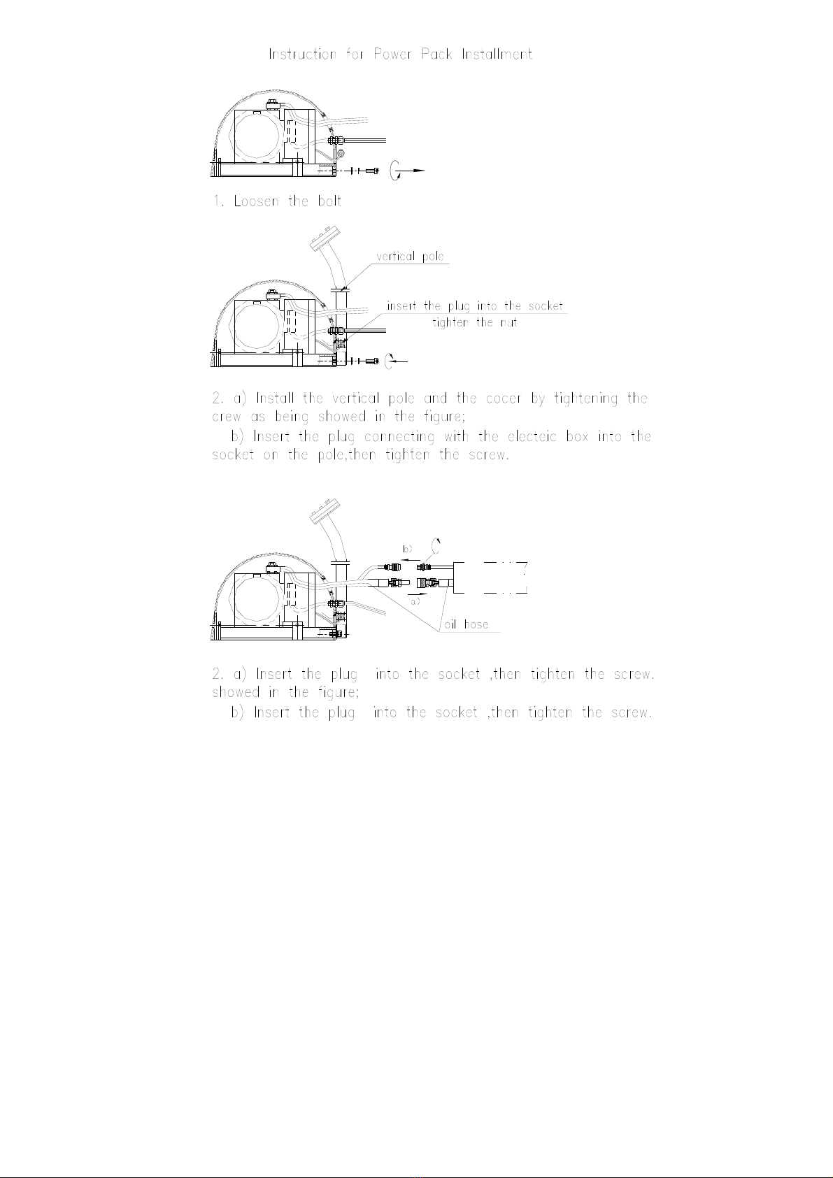
◇ Screw and loose emergency stop switch.
◇ Push the UP button and power pack starts to work to lift the load.
◇ Loose the UP button and power pack stops working.
■ Lowering the Table
WARNING! Do not put foot or hand in
scissors mechanism.

4
◇ Push the DOWN button and the table will lower.
◇ Loose the DOWN button and the table will stop.
NOTE
◇ The table is equipped with an aluminum guard to avoid accidental
danger.
◇ If aluminum guard strikes an object while the table lowers, stop
operation and check the lift table. After making sure no any abnormality,
strike the UP button slightly and then the electric system will function as
before.
◇ Emergency stop
◇ There are two methods of emergency stop as follows.
◇ Push down the emergency stop switch and the movement of table
stops.
◇ Strike aluminum guard upward and the movement of table also stops.
■ Transportation
If necessary, the lift table can be transported with attached ringbolts.
◇ Pay attention to the maximum capacity of lifting equipment to be used.
◇ Keep the ringbolts with reasonableness.

5
5.SPECIFICATIONS
Motor
Model Capacity
(kg) Min. Height
(mm) Max. Height
(mm)
Platform
Length
(mm)
Platform
Width
(mm)
Approx. Lifting
Time while
Loaded Rated
Capacity Output
(w) Voltage
(V) Revolution
(r/min) Protection
Class Insulation
Class
Net Weight
(kg)
HY1001 1000 85 860 1450 1140 ≤20s 1100 415 1400 IP.54 F 357
HY1002 1000 85 860 1600 1140 ≤20s 1100
415 1400 IP.54 F 364
HY1003 1000 85 860 1450 800 ≤20s 1100
415 1400 IP.54 F 326
HY1004 1000 85 860 1600 800 ≤20s 1100
415 1400 IP.54 F 332
HY1005 1000 85 860 1600 1000 ≤20s 1100
415 1400 IP.54 F 352
HY1501 1500 105 880 1600 800 ≤20s 1500
415 1400 IP.54 F 362
HY1502 1500 105 880 1600 1000 ≤20s 1500
415 1400 IP.54 F 401
HY1503 1500 105 880 1600 1200 ≤20s 1500
415 1400 IP.54 F 415
HY2001 2000 105 880 1600 1200 ≤20s 2200
415 1400 IP.54 F 419
HY2002 2000 105 880 1600 1000 ≤20s 2200
415 1400 IP.54 F 405
6.HYDRAULIC CIRCUIT & ELECTRIC PRINCIPLE DIAGRAM
See Figure 1 & Figure 2.
Fig. 1 Hydraulic circuit

6
35W 0-18-24V/200,
19 B TRANSFORMER 240,380,400 1
18 Q
SUBVOLTAGE OVERCURRENT
GUARD LIMIT 1 USER PROVIDE
FOR ONESELF
17 M HYDRAULIC POWER PACK 1
16 FL MALFUNCTION LIMIT SWITCH ME-8104 7
15 XL
LOWERING LIMIT SWITCH 1
USER PROVIDE
FOR ONESELF
14 SL LIFTING LIMIT SWITCH ME-8104 1
13 AN3 EMERGENCY STOP 1
12 AN2 DOWN BUTTON 1
11 AN1 UP BUTTON 1
10 K3 RELA
Y
943-1C-24DS 1 7A
9 K2 RELA
Y
HRS2H-S-DE24V 1
8 K1 RELA
Y
943-1C-24DS 1 7A
7 J1 CONTACTOR K6, AC24V 1
6 C ELECTROLYTIC CAPACITOR 470U50V 1 HORIZONTAL
5 V2 SILICON DIODE 1A 1
4 V1 SILICON RECTIFYING BRIDGE 5A 1
3 R3 RESISTOR 1.8KΩ/1W 1
2 R2 FASTACTING FUSE 3A 1
1 R1 FASTACTING FUSE 0.25A 1
NUMBER SYMBOL NAME MODEL&STANDARD QUANTITY REMARK
Fig. 2 Electric Principle Diagram

7
7.Service INSTRUCTIONS
■ Do routine check of fasteners, packing and oil leaking.
■ Do routine check of the function of the lift table.
■ Before service the lift table, make sure to turn off the AC power supply.
■ After service it is necessary to check the function of the lift table again.
■ ONLY a qualified personnel can do service work.
■ Do routine check of the micro-switches on the safety guard.
■ Do routine check of the hydraulic system by listening its noise, touch
motor’s surface.
Caution: It is necessary to turn off the AC power supply before touch
motor’s surface.
■ Pay attention to clear or even replace the oil filter after operating for a
long time.
■ Appropriate lubrication is necessary to make the lift table work easily
and have a prolonged service life.
■ Following table is recommended to service the lift table periodically.
Content After every 500
hours’ working or
every 3 months later
After every 2000
hours’ working o
r
every year
Check oil level of oil tank ☆
Check the cleanliness of oil filter ☆
Fasten all the connecting parts again ☆
Check wear and tear of pressure oil pipes ☆
Check hydraulic cylinder ☆
Fix main parts tightly again ☆
Check the function of micro-switches ☆
Check whole working state of the lift table ☆
Lubricate all the joints and pivot points ☆
Check wear and tear of all axial bushes ☆
Replace hydraulic oil for the first time Accumulated working ten hours’
Replace hydraulic oil ☆
Check oil leaking ☆
Remark:
☆
stands for proceeding the item.
8

9
8.TROUBLE SHOOTING
Note: Before service it is necessary to screw two eyebolts into relevant
screw-holes on the basis lest the table lowers accidentally
Trouble Cause Remedy
Table cannot
lift while
motor works
normally
◇ Eyebolt has not been
removed
◇ AC voltage phrases
mistake
◇ Electromagnetic
dysfunctions
◇ The table is overloaded
◇ Remove eyebolt
◇ Correct AC voltage phrase
◇ Check the function of
electromagnetic valve and repair
it
◇ Remove excessive load
Table cannot
lift and motor
does not
work
◇ Lowering limit switch (if
existed) damaged ◇ Replace limit switch
Table cannot
lower
◇ Lowering limit switch or
micro-switch on safety guard
damaged
◇ Electromagnetic valve
dysfunctions
◇ Safety guard works
◇ Something wrong with
electric circuit board
◇ Replace lowering limit
switch or micro-switch.
◇ Check the function of
electromagnetic valve and repair
it
◇ Strike the UP button
slightly
◇ Replace electric circuit
board
Table’s legs
go over limit
position (if
existed)
while table
lowers
◇ Internal leaking in
electromagnetic valve
◇ Packing damaged in
hydraulic cylinder
◇ Repair electromagnetic
valve and if necessary replace it
◇ Check and replace packing
Table cannot
reach the
highest
position
◇ Oil not enough
◇ Limit switch damaged
◇ Fill enough oil
◇ Check and repair limit
switch. If necessary, replace it

10
LIFT TABLE HY
NO. Description Model Qty
1 HY main frame 1
2/C01 Power Control Assambly 1
3 Slope 1
HY Main Frame

11
HY Main Frame
NO. Description Model Qty
1 Chassis 1
2 Fixed plate 1
3 Washer Ø6 2
4 Inner hexagon screw M6*10 2
5 Safety switch 8104 7
6 Bolt M4*10 14
7 Bolt M4*25 14
8 Eyebolt 3
9 Scissor 1
10 Self-locking nut M24 2
11 Washer 2
12 Washer 2
13 Shear fork shaft 2
14 Include shaft 2
15 Circlip for shaft Ø20 2
16 Self-lubricating iron set SF10-2030 2
17 Roller 2
18 Self-lubricating iron set SF10-2025 4
19 Roller 4
20 Round pin Ø6*40 4
21 Catch 8
22 Limit piece 1
23 Table 1
24 Link block 6
25 Self-locking nut M6 4
26 Fill block 4
27 Bolt M6*45 8.8级4
28 Self-lubricatingiron set SF10-2210 4
29 Roller 4

12
30 Self-lubricatingiron set SF10-2215 2
31 Circlip for shaft Ø22 4
32 Axle 2
33 Roller 2
34/H03 Hydro-cylinder 2
35 Bolt M8*30 2
36 Spring washer Ø8 2
37 Endcap for hydro-cylinder HU1000-02-11 2
38 Link bolt M14*1.5 2
39 Bonded washer Ø14 4
40 Oil pipe 1
41 Seal ring 2
42 Quick disconnect coupling M16*1.5 1
43 Oil pipe 700mm 3000mm 1
44 O ring 3
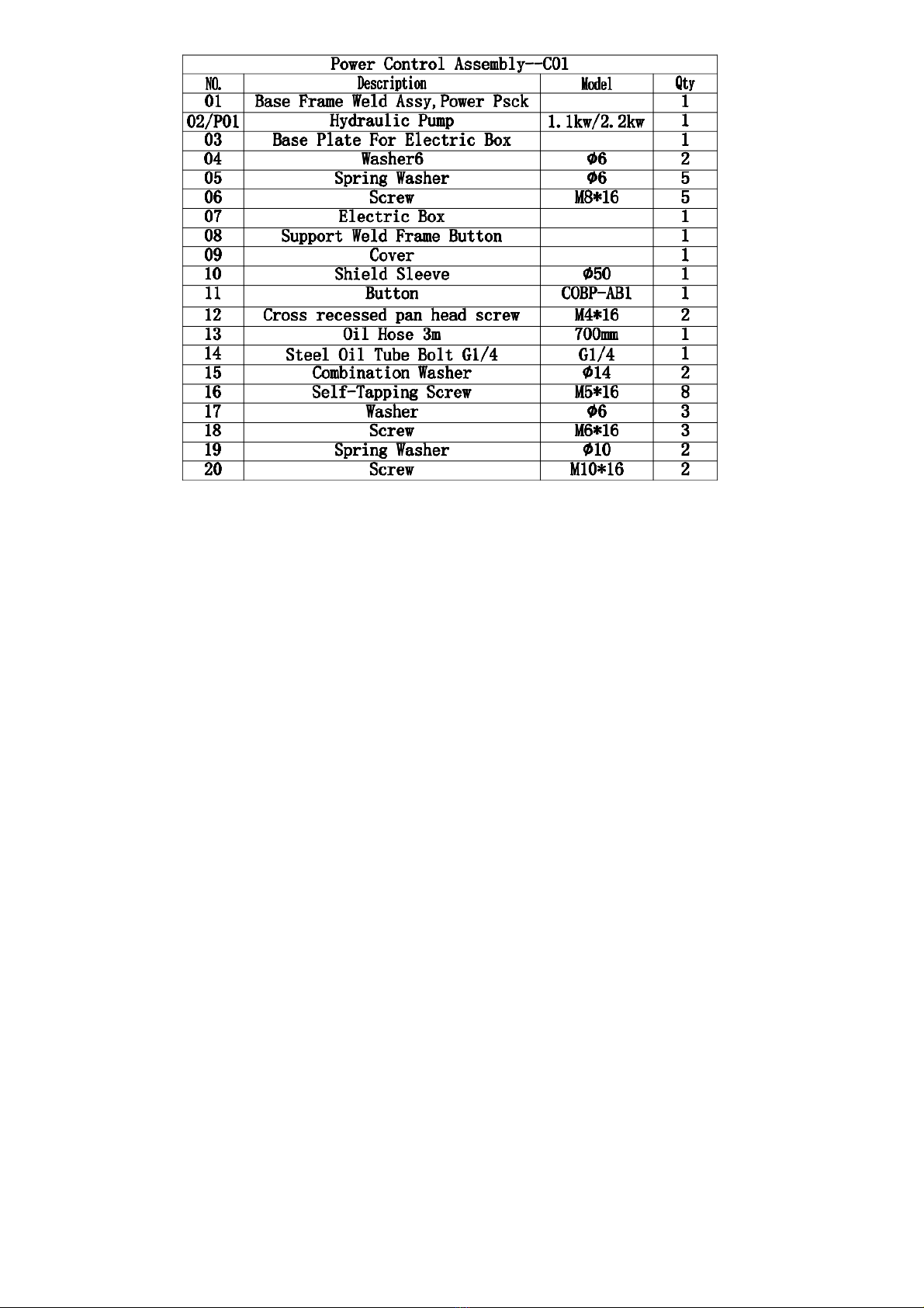
Power Control Assambly—CO1
13
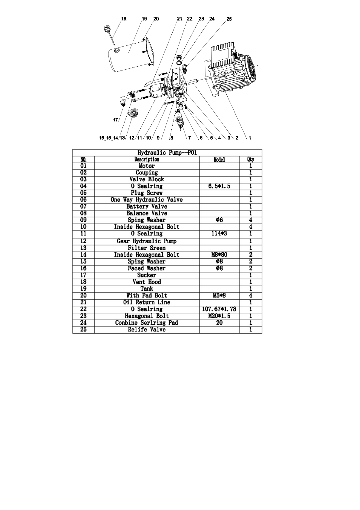
Hydraulic Pump-P01
14
.

15
Electric Box
This manual suits for next models
9
Table of contents


