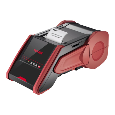
Postek iQ200 User manual


FCC Notice
This device complies with Part 15 of the FCC Rules. Operation is subject to the following two
conditions: (1) this device may not cause harmful interference, and (2) this device must accept any
interference received, including interference that may cause undesired operation.
This equipment may generate, use and/or radiate radio frequency energy. If not installed and used in
full accordance with this User’s Manual, interference to radio communications may occur. This
equipment complies with the limits for a Class A Information Technology Equipment pursuant to
Part 15 of the FCC Rules, which are designed to provide reasonable protection against such
interference when operated in a commercial environment. Operation of this equipment in a
residential area may also cause interference. In such case the user, at his/her expense, will be
required to correct the interference using whatever means necessary.
Trademarks
POSTEK is a registered trademark by POSTEK Electronics Co., Ltd.
ARM is a registered trademark of Advanced RISC Machines Ltd.
Microsoft, Windows are registered trademarks of Microsoft Corporation.
Copyright
© 2021 by Postek Electronics Co., Ltd. All rights reserved. Under the copyright laws, this manual
cannot be reproduced in any form without the prior written permission of POSTEK. No patent
liability is assumed, with respect to the use of the information contained herein.
Disclaimer
POSTEK barcode/RFID printers are developed and produced by Postek Electronics Co., Ltd
(hereinafter as “POSTEK”) with the adoption of direct thermal/thermal transfer printing and RFID
encoding techniques. For thermal transfer printing, matching ribbons and media are required.
Meanwhile, the wide variety of RFID chip and antenna designs make it difficult to guarantee RFID
tag’s 100% compatibility with POSTEK printers, to satisfy your printing needs, please consult with
the local reseller(s) to choose the matching consumables for POSTEK printers.
This manual has been validated and reviewed for accuracy. The instructions and descriptions it
contains are accurate for the POSTEK printer at the time of this manual’s distribution. However,
succeeding printers and manuals are subject to change without notice. POSTEK assumes no liability
for damages incurred directly or indirectly from errors, omissions or discrepancies between the
printer and this manual.
To protect your interest, and to prevent loss due to improper handling, please read the

corresponding user’s manual before operation, and don't use the printer during abnormal conditions.
In no event shall POSTEK be liable for any damage or loss caused by human misoperation,
including but not limited to loss of business profits, business interruption, loss of business
information, or other pecuniary loss.
Although this manual describes and details many issues which could possibly occur, the
manufacturer cannot warrant against unpredictable conditions during the printer’s application. For
problems such as the printer not working, missed or unclear print content, etc., POSTEK and/or its
resellers are responsible for troubleshooting (according to POSTEK Warranty Clauses). In no event
shall POSTEK or the resellers involved be liable for any direct or indirect loss, including but not
limited to loss of business profits, business interruption, loss of business information, or other
pecuniary loss.
Important Safety Instructions
•Only qualified and trained service technicians should attempt to repair the printer.
•Do not place the printer on or near a heat source.
•Be sure that the output of the power adapter is 24VDC and your power source matches the
rating listed on the power adapter. Be certain your power source is grounded.
•To avoid getting an electric shock, do not use a worn or damaged power cord. If the power cord
becomes damaged or frayed, replace it immediately.
•Do not insert anything into the ventilation slots or openings on the printer.
•The printer and power adapter should never be operated in a location where either one can get
wet. Personal injury may result.
•The printhead becomes hot while printing. To protect from damaging the printhead and risk of
personal injury, avoid touching the printhead.
•To get increased printhead longevity and higher quality printouts, always use approved labels,
tags and thermal transfer ribbons. Approved supplies can be ordered from your Postek
authorized reseller.
•Static electricity that accumulates on the surface of the human body or other surfaces can
damage or destroy the printhead or electronic components in this device. DO NOT touch the
printhead or the electronic components with bare hands.
•Place the printer on a flat, firm, solid surface.
•Never operate in a high temperature environment.
•Turn off the power when not in use for extended periods.
•Follow all recommendations and setup instructions included in this manual.

iQ200 User’s Manual Contents
i
Contents
Preface ..........................................................................................................................1
Important Notes...........................................................................................................2
Chapter 1: Introduction..............................................................................................3
1.1 Specifications.........................................................................................................................3
1.2 Contents in the Box................................................................................................................4
Chapter 2: Setup and Use...........................................................................................5
2.1 Main Parts and Structures......................................................................................................5
2.1.1 Front View.....................................................................................................................5
2.1.2 Internal View.................................................................................................................6
2.1.3 Rear View......................................................................................................................7
2.2 Setting up the Printer..............................................................................................................8
2.2.1 Interface Connection.....................................................................................................8
2.2.2 Connecting the Printer ..................................................................................................8
2.2.3 Loading the Media........................................................................................................9
2.3 Using the External Media Stand ..........................................................................................12
2.4 Changing the Position of Reflective Media Sensor.............................................................17
Chapter 3: Operations and Settings ........................................................................20
3.1 Basic Operations..................................................................................................................20
3.1.1 Power Switch ..............................................................................................................20
3.1.2 The Front Panel...........................................................................................................20
3.1.3 Advanced Functions....................................................................................................22
3.1.4 DIP Switches...............................................................................................................23
3.1.5 Setting Operation Mode..............................................................................................25
3.2 WIFI Settings.......................................................................................................................26
3.3 Installing Windows Driver and Label Editing Software......................................................27
Chapter 4: Maintenance...........................................................................................28
4.1 Cleaning the Printhead.........................................................................................................28
4.2 Cleaning the Platen Roller ...................................................................................................28
4.3 Cleaning the Printer Interior ................................................................................................29
4.4 Cleaning the Sensors............................................................................................................29
Chapter 5: Troubleshooting......................................................................................30
5.1 LED Error Indications..........................................................................................................30
5.2 Miscellaneous Issues............................................................................................................31
Appendix
A: Interface Specifications......................................................................32
Appendix B: ASCII Table.........................................................................................33
iQ200 User’s Manual Preface
1
Preface
This manual explains how to set up and begin using your iQ printer. It also provides detailed
information on configuring your printer, basic operations, care and troubleshooting.
Please read this manual carefully before using the POSTEK iQ printer.
Symbol Conventions
The symbols that may be found in this document are defined as follows.
Symbol
Description
Alerts you to a medium or low risk hazard that could, if not avoided, result
in moderate or minor injury.
Alerts you to a potentially hazardous situation thatcould, if not avoided,
result in equipment damage, data loss, performance deterioration, or
unanticipated results.
Provides additional information to emphasize or supplement important
points in the main text.
Version
Version 1.2, published in August, 2021.

iQ200 User’s Manual Important Notes
2
Important Notes
Please read the following passages thoroughly before proceeding.
Printhead
The thermal printhead can be easily damaged due to its precision construction. A printhead
damaged by misuse is not covered under the terms of the warranty. To ensure longevity of the
printhead, please note the following:
•DO NOT scrape or use tools that might damage the printhead surface.
•To protect from corroding the printhead, DO NOT touch the printhead with bare hands.
•DO NOT use thermal paper or thermal transfer ribbons which contain Na, K or Cl elements.
•Keep printhead from any form of liquid or dampness.
•Only use a cotton swab dipped in anhydrous isopropyl alcohol to clean the printhead.
•Always use high-quality consumables:
➢When the printhead module is closed, pressure is placed directly onto the printhead; dirt
such as paper scraps, sand, dust and glue can scrape or damage the printhead.
➢Therefore, please always inspect consumables for high quality before purchasing. Any
printhead damage caused by poor quality consumables is not covered under warranty.
Cutter (Optional)
The printer equipped with a cutter can automatically cut the label after printing. However,
automatic cutters pose a safety hazard since the blades are very sharp. To prevent injuries and cutter
failures while using one of the many types of automatic cutters, please follow the safety and
maintenance rules listed below:
•Before using the cutter, be sure you have been trained by a qualified individual. A written
procedure covering the cutter's use is recommended.
•It is very important to choose the right cutter model for the application to ensure personal safety
and prevent damage to the cutter caused by cutting wrong types of media.
•Keep loose items such as long hair, clothing, jewelry, away from the cutter.
•Don't put anything except print media inside the cutter.
•Turn off power of printer if you notice abnormality with the cutting process and alert a
qualified technician to resolve the issue.
•Never cut a print media which exceeds the maximum operating conditions of the cutter.
•Not every cutter model is designed to be able to cut through adhesive. Use only the dedicated
cutters to cut through adhesive materials. Even so, regular cleaning is required to remove the
adhesive built up on the blades over time to prevent cutter jam.
•Routine inspection and maintenance are required to be performed by a qualified technician to
keep the cutter in good working conditions.

iQ200 User’s Manual Chapter 1: Introduction
3
Chapter 1: Introduction
1.1 Specifications
Item
Description
Printing Mode
Direct Thermal
Resolution
203dpi
Max Printing Speed
6 ips (152.4 mm/s)
Max Printing Width
4.09″ (104 mm)
Max Printing Length
40″(1016 mm)
HEATTM Level
II
Memory
8 MB FLASH ROM, 16 MB SDRAM
Media
Width: 4.72″(120 mm) max., 0.98” (25 mm) min.
OD: 5″ (127 mm) max. or 9″ (228.6 mm) max. (using External Media
Stand).
ID: 1″ (25.4 mm) min.
Media Thickness
0.0023″ ~ 0.0098″ (0.06 ~ 0.25 mm), including liner
Media Sensor
Reflective/Transmissive
Fonts
Five built-in dot matrix ASCII fonts, user-downloadable TrueType Fonts
Barcode Types
1D Barcode: Code 39, Code 93, Code 128/subset A,B,C, Codabar,
Interleave 2 of 5, UPC A/E 2 and 5 add-on, EAN-13/8/128, UCC-128,
etc.
2D Barcode: MaxiCode, PDF417, Data Matrix, QR Code, etc.
Interfaces
RS-232 Serial, USB DEVICE 2.0
Power Adapter
Input: AC100~240 V, 50~60 Hz
Output: DC 24 V, 2.5 A
Weight
3.97 lbs (1.8 kgs)
Dimensions
W 8.58″ (218mm) x D 10.0″(255mm) x H 5.91″(150 mm)
Operating
Environment
Temperature: 32F ~ +104F (0C ~ 40C)
Relative humidity: 5% - 85% non condensing
Storage environment
Temperature: -40F ~ +140F (-40C ~ 60C)
Relative humidity: 5% - 85% non condensing
Optional Items
Wi-Fi, Bluetooth, Guillotine Cutter, External Label Rewinder, Media
Guide Adapter, 10/100 M Adaptive Ethernet Port
HEATTM, or Heating Equilibrium Adaptive Tuning, is a POSTEK designed and developed
cutting-edge technology that sets the benchmark for heat management in thermal printing. Printers
equipped with HEATTM have significant improvements in their printout clarity and print speed. The
HEATTM level represents the fineness of the heating uniformity with level I being the finest.

iQ200 User’s Manual Chapter 1: Introduction
4
1.2 Contents in the Box
Inspect the shipping carton(s) for possible shipping damage, if damage is discovered, notify the
shipping company to report the nature and extent of the damage.
Please check the items according to the Quick Start Guide. If there are any items missing, notify
your authorized reseller.

iQ200 User’s Manual Chapter 2: Setup and Use
5
Chapter 2: Setup and Use
2.1 Main Parts and Structures
2.1.1 Front View
Figure 2-1 Front View
Table 2-1 Front View Description
Number
Description
1
[READY] Indicator
2
[MEDIA] Indicator
3
WIFI Indicator
4
[PAUSE/Self Test] Button
5
[FEED/Calibration] Button
6
[CANCEL/Reset] Button
7
Tear-off Bar
8
Cover Handle
9
Observation Window

iQ200 User’s Manual Chapter 2: Setup and Use
6
2.1.2 Internal View
Figure 2-2 shows the detailed structure of the printer.
Figure 2-2 Internal View
Table 2-2 Internal View Description
Number
Description
1
Handle
2
Printhead Assembly
3
Platen Roller
4
Media Guide
5
Media Guide Rod
6
Media Compartment

iQ200 User’s Manual Chapter 2: Setup and Use
8
2.2 Setting up the Printer
2.2.1 Interface Connection
When connecting the iQ printer to a computer via the USB interface cable, make sure to utilize the
same USB port used during the driver installation process. If the same USB port is not available or
not known, then please go to the printer driver’s Properties Dialogue Box, and make sure the
correct port is checked under the Ports tab.
The iQ supports RS-232 Serial and USB interface connections, you can choose to connect the
printer to the computer via these ports.
To connect:
•Make sure the printer is powered OFF.
•The printer will identify the communication port automatically.
•The default values of printer port can be obtained from the self-test report (see 3.1.3 Advanced
Functions/Obtaining Printer Configuration Information).
•Cable configurations for Serial (RS-232C) interface can be found in Appendix
A: Interface
Specifications of this guide.
•Please take the following measures to reduce cable noise.
➢Restrict the length of the interface cable to less than 6’ (1.83 M) if possible.
➢Keep the interface cable separate from power cords.
2.2.2 Connecting the Printer
⚫Do not use the printer near liquids or corrosive chemicals.
⚫Using the wrong power adapter may cause damage to your printer. POSTEK assumes no
liability for any damage in such cases. The rating for the printer is 24VDC.
1. Make sure the printer is switched OFF.
2. Connect the power cord to the Power Adapter
3. Connect the Power Adapter’s DC output plug to the DC IN port on the back of the printer.
4. Plug the power cord into a live wall outlet.

iQ200 User’s Manual Chapter 2: Setup and Use
9
2.2.3 Loading the Media
iQ printer can be operated under four different modes: Standard Mode, Tear-off Mode, Cutter Mode,
and Peeler Mode.
•In Standard Mode, the printer stops and goes into standby as soon as the print job is complete.
•In Tear-off Mode, after the print job is finished, the printer will feed the label until the edge of
it aligns with the edge of the Tear-off Bar allowing easy tear off for the user.
•In Cutter Mode, the printer stops and cuts the printed label(s) (Only available on models with
cutter installed).
•In Peeler Mode, printer stops and waits for the printed and peeled off label to be taken away
before resuming the print job (Only available on models with peeler installed).
Standard Mode
To load media into the iQ printer while under Standard Mode, follow the steps below:
1. Lift the right cover of the printer and lift the Handle of the Printhead, as shown in Figure 2-4.
Figure 2-4 Lift the Handle
2. Load a roll of media (labels facing up) on the Media Spindle, then slide the two Media Roll
Guides, with smooth sides facing toward the media, onto the Media Spindle from each end until
both Media Roll Guides touch the media. When placing a roll of media with a 3″ ID core,
please slide the two Core Adapters onto the Media Spindle first, as shown in Figure 2-5.

iQ200 User’s Manual Chapter 2: Setup and Use
10
Figure 2-5 Place Media Roll on Media Spindle
3. Place the entire unit into the printer’s Media Compartment.
4. Position the media roll in the middle of the Spindle, using the ruler on the Media Spindle for
alignment. See Figure 2-6.
Figure 2-6 Load the Media
Media Roll
Media Roll Adaptors
Media Spindle
Media Roll Guide
Media Roll
Module correctly
fitted with Spindle
and Guides

iQ200 User’s Manual Chapter 2: Setup and Use
11
5. Thread the media under the Media Guide Rod, over and pass the Platen Roller to the front of
the printer.
6. Slide the Media Guide to the edge of the media, making sure that the media remains flat and is
placed in the middle of the Tear-off Bar. This can be checked with the ruler on the Tear-off Bar.
See Figure 2-7.
Figure 2-7 Media Loaded
7. Press down the Handle of the Printhead to lock the Printhead. See Figure 2-7.
8. Turn on the printer, press and hold the [FEED/Calibration] button (hold for around 4 seconds),
then the printer will automatically feed labels and the media calibration is done.
Calibration must be made when media is loaded to the printer for the first time, or when there
is a change to a different type of media.
Media Guide

iQ200 User’s Manual Chapter 2: Setup and Use
12
2.3 Using the External Media Stand
It is recommended to install the External Media Stand when the outer diameter of the media roll is
larger than 4 inches or when fanfold media is applied.
Label Roll
To load label roll on External Media Stand, follow the steps below:
1. Place the front part of the External Media Stand under the printer, making sure the two rear
rubber feet of the printer are fitted into the two holes on the media stand, see Figure 2-8.
Figure 2-8 Place the External Media Stand
2. Lift the right cover of the printer and lift the Handle of the Printhead. See Figure 2-9.
External Media Stand
Rear rubber feet

iQ200 User’s Manual Chapter 2: Setup and Use
13
Figure 2-9 Lift the Handle
3. Load a roll of media (labels facing up) on the Media Spindle, then slide the two Media Roll
Guides, with smooth sides facing toward the media, onto the Media Spindle from each end until
both Media Roll Guides touch the media. When placing a roll of media with a 3″ ID core,
please slide the two Core Adapters onto the Media Spindle first, as shown in Figure 2-10.
4.
Figure 2-10 Place Media Roll on Media Spindle
5. Place the entire unit onto the External Media Stand.
Media Roll
Media Roll Adaptors
Media Spindle
Media Roll Guide
Media Roll
Module correctly
fitted with Spindle
and Guides

iQ200 User’s Manual Chapter 2: Setup and Use
14
6. Position the media roll in the middle of the Spindle, using the ruler on the Media Spindle for
alignment. See Figure 2-11.
Figure 2-11 Load the Media
7. Thread the media under the Media Guide Rod, over and pass the Platen Roller to the front of
the printer.
8. Slide the Media Guides to the edge of the media, making sure that the media remains flat and is
placed in the middle of the Tear-off Bar. This can be checked with the ruler on the Tear-off Bar.
See Figure 2-12.
Figure 2-12 Thread the Media
9. Press down the Handle of the Printhead to lock the Printhead, then close the right cover. See
Figure 2-13.
Media Guide

iQ200 User’s Manual Chapter 2: Setup and Use
15
Figure 2-13 Media loaded
Fanfold Label
To load fanfold media on External Media Stand, follow the steps below:
1. Place the front part of the External Media Stand under the printer, making sure the two rear
rubber feet of the printer are fitted into the two holes on the media stand, see Figure 2-14.
Figure 2-14 Place the External Media Stand
2. Lift the right cover of the printer and lift the Handle of the Printhead. See Figure 2-15.
External Media Stand
Rear rubber feet

iQ200 User’s Manual Chapter 2: Setup and Use
16
Figure 2-15 Lift the Handle
3. Thread the folded label through the media slot at the rear end of the printer, and go on to thread
the media under the Media Guide Rod, over and pass the Platen Roller to the front of the
printer.
4. Slide the Media Guides to the edge of the media, making sure that the media remains flat and is
placed in the middle of the Tear-off Bar. This can be checked with the ruler on the Tear-off Bar.
See Figure 2-16.
Figure 2-16 Thread the Media through Media Slot
5. Press down the Handle of the Printhead to lock the Printhead, then close the right cover. See
Figure 2-17.
Table of contents
Other Postek Label Maker manuals

Postek
Postek G2000e User manual

Postek
Postek TX SERIES User manual

Postek
Postek V8i User manual

Postek
Postek IQ SERIES User manual

Postek
Postek I Series User manual

Postek
Postek G-2108 User manual

Postek
Postek I Series User manual

Postek
Postek Q8 User manual

Postek
Postek TX Exp Series User manual

Postek
Postek C168 User manual