CONNECTING A RECEIVER
The Aura 8 supports three separate connection methods - direct connection of up to (2)
DSM2/DSMX remote receivers; data connection for Futaba S.Bus, JR XBus (Mode B),
Graupner HOTT, DSM SRXL, and certain PPM streams; and traditional PWM connections.
Follow the diagrams below to appropriately connect the Aura to a receiver of your choice.
Note that these connections are basic representations, and that the app provides much
more exibility in the types of setups possible with the AURA.
COMPLIANCE INFORMATION FOR THE EUROPEAN UNION
LIMITED WARRANTY
Warranty Coverage - Flex Innovations, Inc. and its authorized resellers (“Flex”) warrant to
the original purchaser that the product purchased (the“Product”) it will be free from
defects in materials and workmanship at the date of purchase.
Outside of Coverage - This warranty is not transferable and does not cover: (i) Products
with more than 45 days after purchased date; (ii) Damage due to acts of God, accident,
misuse, abuse, negligence,commercial use, or due to improper use, installation, operation
or maintenance; (iii) Modication of or to any part of the Product; (iv) Product not
compliant with applicable technical regulations; (v) Shipping damage; (vi) Cosmetic
damage.
OTHER THAN THE EXPRESS WARRANTY ABOVE, FLEX MAKES NO OTHER WARRANTY OR
REPRESENTATION, AND HEREBY DISCLAIMS ANY AND ALL IMPLIED WARRANTIES,
INCLUDING, WITHOUT LIMITATION, THE IMPLIED WARRANTIES OF NONINFRINGEMENT,
MERCHANTABILITY AND FITNESS FOR A PARTICULAR PURPOSE. THE PURCHASER
ACKNOWLEDGES THAT THEY ALONE HAVE DETERMINED THAT THE PRODUCT WILL
SUITABLY MEET THE REQUIREMENTS OF THE PURCHASER’S INTENDED USE.
Purchaser’s Solution - Flex’s sole obligation and purchaser’s sole and exclusive remedy
shall be that Flex will, at its option, either (i) service, or (ii) replace, any Product determined
by Flex to be defective. Flex reserves the right to inspect any and all Product(s) involved in
a warranty claim. Service or replacement decisions are at the sole discretion of Flex. Proof
of purchase is required for all warranty claims. SERVICE OR REPLACEMENT AS PROVIDED
UNDER THIS WARRANTY IS THE PURCHASER’S SOLE AND EXCLUSIVE REMEDY.
Limitation of Liability - FLEX SHALL NOT BE LIABLE FOR SPECIAL, INDIRECT, INCIDENTAL
OR CONSEQUENTIAL DAMAGES, LOSS OF PROFITS OR PRODUCTION OR COMMERCIAL LOSS
IN ANY WAY, REGARDLESS OF WHETHER SUCH CLAIM IS BASED IN CONTRACT, WARRANTY,
TORT, NEGLIGENCE, STRICT LIABILITY OR ANY OTHER THEORY OF LIABILITY, EVEN IF FLEX
HAS BEEN ADVISED OF THE POSSIBILITY OF SUCH DAMAGES.
Further, in no event shall the liability of Flex exceed the individual price of the Product on
which liability is asserted. As Flex has no control over use, setup, assembly, modication or
misuse, no liability shall be assumed nor accepted for any resulting damage or injury. By
the act of use, setup or assembly, the user accepts all resulting liability. If you as the
purchaser or user are not prepared to accept the liability associated with the use of the
Product, purchaser is advised to return the Product immediately in new and unused
condition to the place of purchase.
Law - These terms are governed by Florida law (without regard to conict of law
principals). This warranty gives you specic legal rights, and you may also have other rights
which vary from state to state. FLEX RESERVES THE RIGHT TO MODIFY THIS WARRANTY
AT ANY TIME WITHOUT PRIOR NOTICE.
Questions & Assistance - For customer support in your region, visit:
http://www.exinnovations.com/index.php/reseller-sub Inspection or Services - If
this Product needs to be inspected or serviced and is compliant in the region you live and
use the Product in, please contact your regional Flex authorized reseller. Pack the Product
securely using a shipping carton. Please note that original boxes needs to be included, but
are not designed to withstand the rigors of shipping without additional protection. Ship
via a carrier that provides tracking and insurance for lost or damaged parcels, as Flex is not
responsible for merchandise until it arrives and is accepted at our facility.
Warranty Requirements - For Warranty consideration, you must include your original
sales receipt verifying the proof of purchase date. Provided warranty conditions have
been met, your Product will be replaced free of charge. Shipping charges are as follow: to
Flex by customer, Flex out it is by Flex. Service or replacement decisions are at the sole
discretion of Flex.
KNOW BEFORE YOU FLY
Know Before You Fly is an education campaign founded by the Association for Unmanned
Vehicle Systems International (AUVSI), the Academy of Model Aeronautics (AMA), and the
Small UAV Coalition in partnership with the Federal Aviation Administration (FAA) to
educate prospective users about the safe and responsible operation of unmanned aircraft
systems (UAS). Please observe the following guidelines when operating your aircraft.
Follow community-based safety guidelines, as developed by organizations such as
the Academy of Model Aeronautics (AMA).
Fly no higher than 400 feet and remain below any surrounding obstacles when possible.
Keep your sUAS in eyesight at all times, and use an observer to assist if needed.
Remain well clear of and do not interfere with manned aircraft operations, and you must
see and avoid other aircraft and obstacles at all times.
Do not intentionally y over unprotected persons or moving vehicles, and remain at
least 25 feet away from individuals and vulnerable property.
Contact the airport or control tower before ying within ve miles of an airport.
Do not y in adverse weather conditions such as in high winds or reduced visibility.
Do not y under the inuence of alcohol or drugs.
Ensure the operating environment is safe and that the operator is competent and
procient in the operation of the sUAS.
Do not y near or over sensitive infrastructure or property such as power stations,
heavily traveled roadways, correctional/water treament/government facilities, etc.
Check and follow all local laws and ordinances before ying over private property.
Do not conduct surveillance or photograph persons in areas where there is an
expectation of privacy without the individual’s permission (see AMA’s privacy policy).
For more safety information, please download the Know Before You Fly brochure at
www.knowbeforeyouy.org.
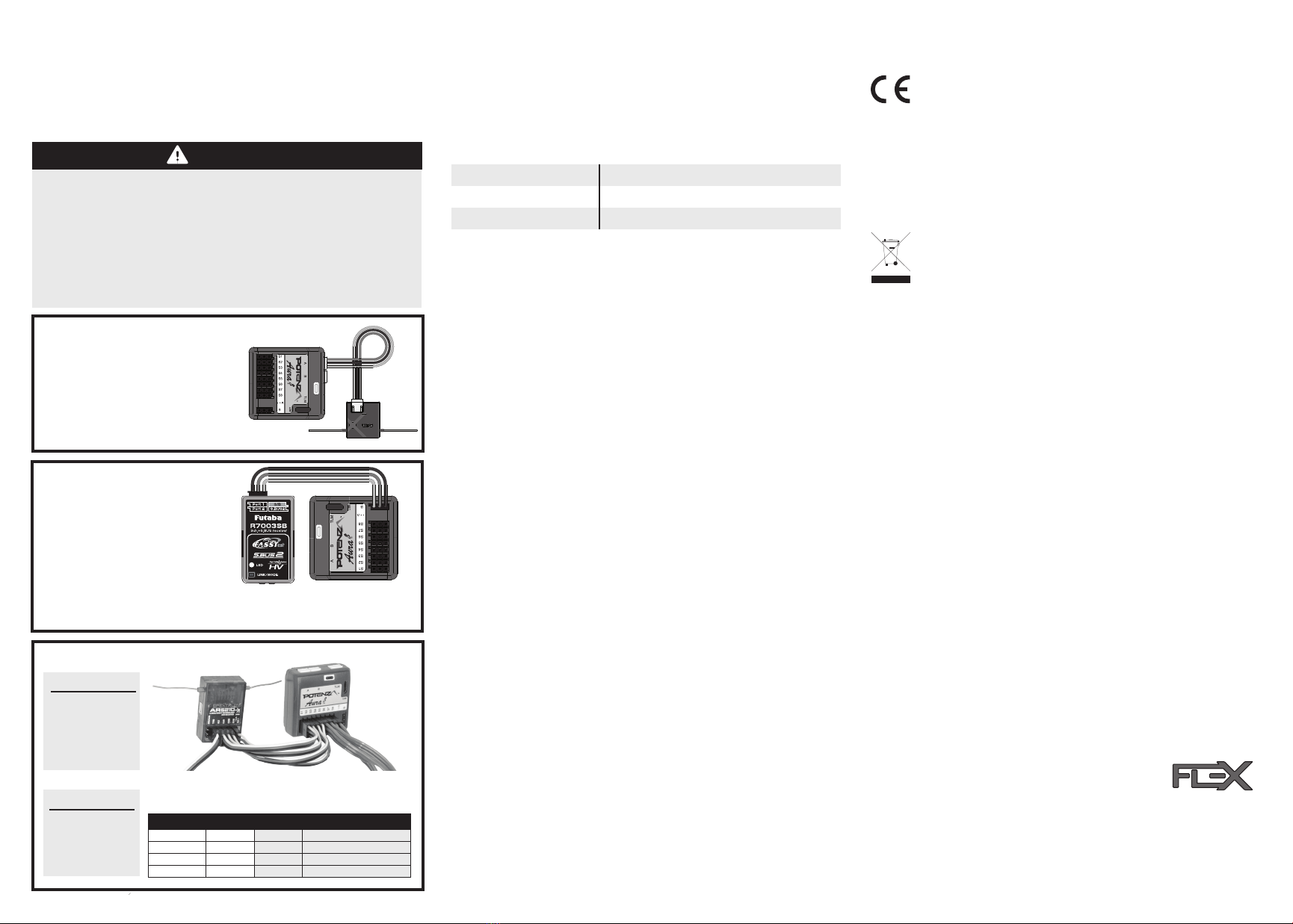
DSM Remote Receiver(s) Connection
Connect up to two (2) remote DSM2/DSMX
receivers to Mini Ports A and B on the front
side of the unit. If only one (1) remote receiver
is being used, it MUST be plugged in to Port ‘A’
Attach the remote antenna securely to the
fuselage using hook-and-loop tape or double
sided foam tape.
Servo Bus Port B Data Connection
Insert the included male to male extension
into Port ‘B’ on the face of the Aura and
connect to your receiver‘s data port:
Futaba S.Bus - S.Bus port
JR XBus (Mode B) - XBus port
Graupner SumD of 8 - Port 8 (typical)
DSM via SRXL - SRXL Port
Certain PPM Streaming Recievers
© 2015 Flex Innovations, Inc.
Premier Aircraft™, Potenza™, and Top Value RC™ are trademarks or registered trademarks of Flex Innovations, Inc.
Android is a trademark of Google Inc. iPhone® is a trademark of Apple Inc registered in the US and other countries.
DSM®, DSM2™, and DSMX™ are trademarks of Horizon Hobby, Inc.
Futaba is a registered trademark of Futaba Denshi Kogyo Kabushiki Kaisha Corporation of Japan.
HoTT is a registered trademark of SJ, Inc.
Created 7/2015
INNOVATIONS
TM
Declaration of Conformity (In accordance with ISO/IEC 17050-1)
Product(s): Aura 8 Advanced Flight Control System
Item Number(s): FPZAURA8
The object of declaration described above is in conformity with the requirements of the
specications listed below, following the provisions of the EMC Directive 2004/108/EC.
EN 55024
EN 55022
EN 61000-4-3
EN 61000-4-3
EN 55022/CISPR 22
Instructions for disposal of WEEE by users in the European Union
This product must not be disposed of with other waste. Instead, it is the
user’s responsibility to dispose of their waste equipment by handing it over
to a designated collections point for the recycling of waste and electronic
equipment. The sepearate collection and recycling of your waste equipment
at the time of disposal will help to conserve natural resources and ensure
that it is recycled in a manner that protects human health and the
environment. For more information about where to drop o your waste
equipment for recycling, please contact your local city oce, your household
waste disposal service or where you purchased the product.
3pc Male to Male Servo/ Serial Bus Cable
FPZAURA08 Aura 8 Flight Contol System (open stock)
FPZAU01
FPZAU02 Micro USB Cable
REPLACEMENT PARTS LISTING
Left Aileron
Rudder
Elevator
CONTROL SURFACE
Right Aileron
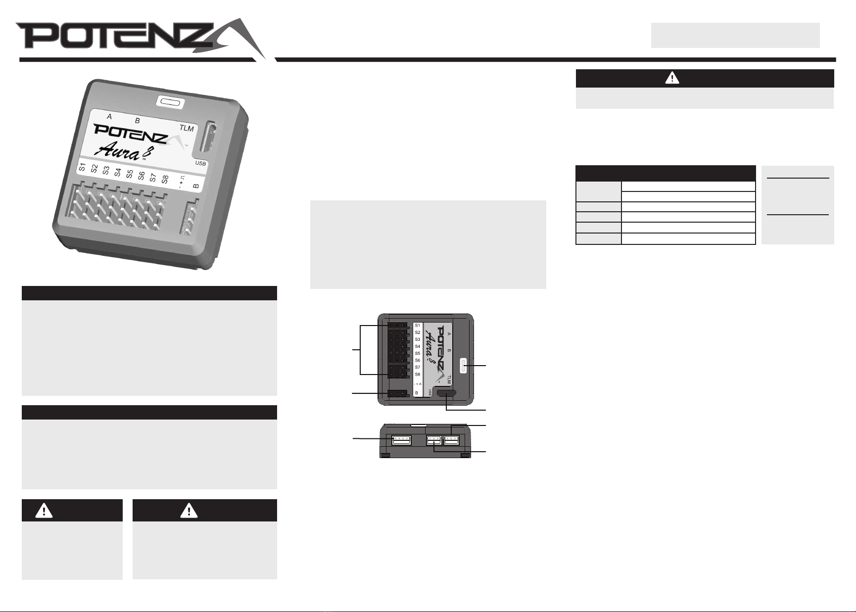
AURA 8
S5
S6
S8
S7
RECEIVER
Aileron
Rudder
Elevator
AURA 8
CH5/Gear S4
S1
S3
S2
CONNECTIONS IN CONNECTIONS OUT
Traditional PWM Connection (Typical Connections)
Lead to
ESC/BEC
Leads to ight
control servos
WARNING
Exercise extreme caution when plugging in any lead that could potentially supply power, or short
power buses. It is possible to 'reverse' or 'short' a power connection by even partially plugging in
a connector. Examples (but not limited to):
§ Connecting multiple batteries or power leads. Use switches, extensions, and Y harnesses
with extreme care.
§ Connecting PWM Cables. Install PWM cables with power removed from the system. Inspect
carefully before powering the system.
THE USER MUST PROVIDE AURA WITH A STABLE AND RELIABLE
POWER SUPPLY. FAILURE TO DO SO COULD RESULT IN LOSS OF
CONTROL OR CRASH.
AURA 8 SOFTWARE CONFIGURATION- PC PROGRAM APP
For advanced users with complex airplanes, visit http://www.exinnovations.com/aura
and follow the links to download the free Aura PC programming app. Select the 'New’
model wizard, which provides step-by-step guidance to create a brand new model
program for the Aura 8. Basic installations and setups (non-PWM) can be accomplished
following the "quick setup" instructions without the use of a PC.
NOTE
The stock Aura 8 (not
pre-installed in any
airframe) will not
auto-detect PWM
connections. Please use
the Applications new
model wizard to
congure for PWM.
NOTE
ESC/THROTTLE WILL
CONNECT TO THE
RECEIVER DIRECTLY. NO
CONNECTION FROM THE
AURA TO RECEIVER WILL
BE MADE FOR THE ESC.
Refer to your radio manufacturer’s instructions for specic information regarding
conguring your system’s serial bus communication settings for use with third party
applications and hardware.