Due to continuous product development Advanced Air (U.K.) Ltd
reserves the right to change any information without prior notice.
Burrell Way,
Thetford, Norfolk,
IP24 3QU, England
Tel: +44 (0) 1842 753624
Fax: +44 (0) 1842 762032
Email: sales@advancedair.co.uk
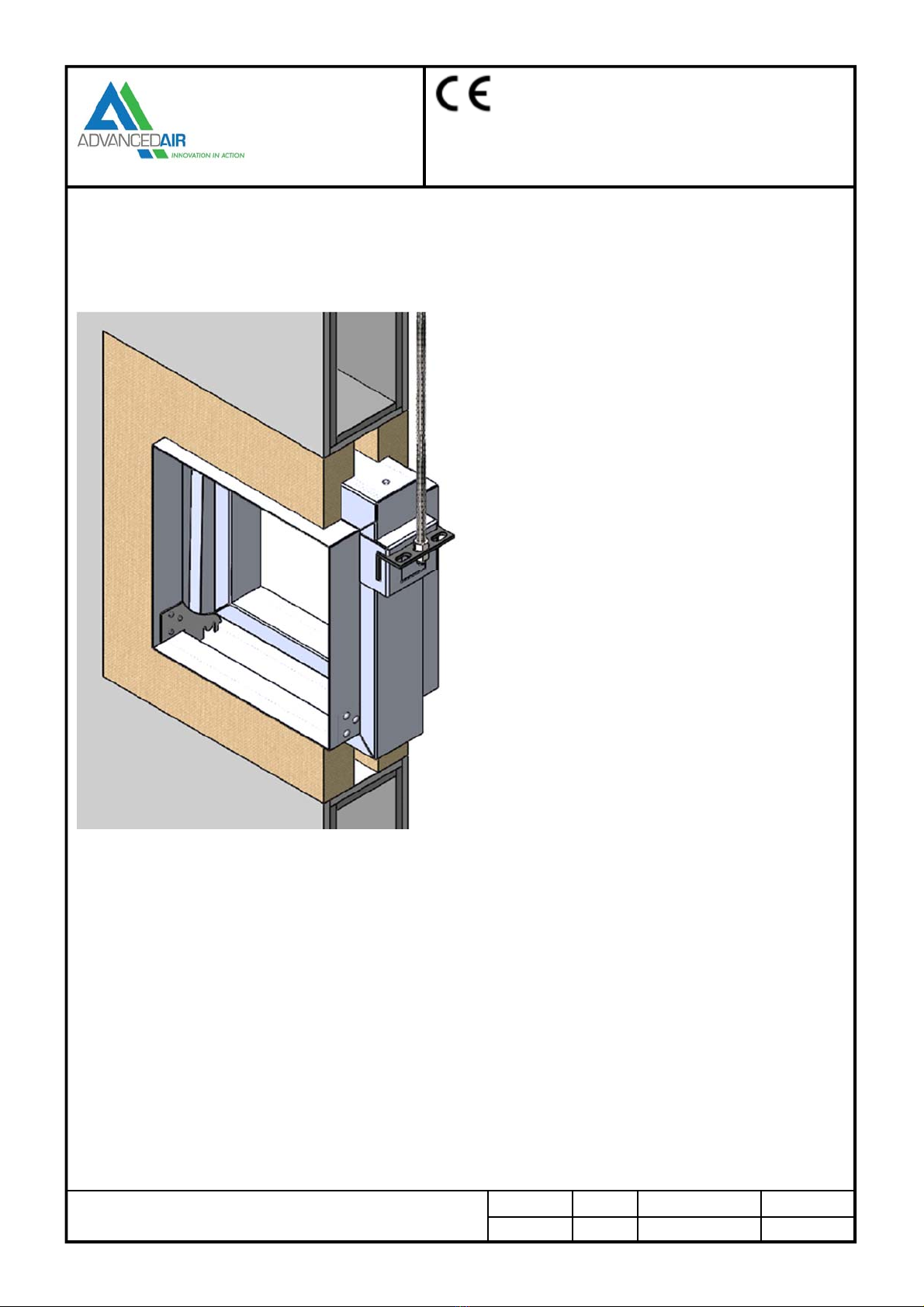
0160 Series
Curtain Fire Dampers
Date Issue Spec. No. Page No.
13/01/15 Rev 4 CE –FD Sub
PATENT APPLIED FOR
6
HEVAC Wall Installation - E120
Installation & Maintenance Instructions
Installation Procedure
1. Vertical builders work barrier to have an appropriately
sized lintel to ensure an opening clearance for the
expansion frame.
2. The opening in the wall must be cleaned, free of dust
and any other contaminants which could impair the
mortar adhesion. A clearance gap 25mm (min) to 50mm
(max) must be maintained around the expansion frame
of the fire damper (barrier contractor).
3. The damper shall be fitted centrally in the wall opening.
4. The tabs on the factory fitted galvanized steel expansion
frame shall be bent out to tie the damper into the wall
with the penetration seal.
5. The “Penetration Seal” must have a structural and fire
rated compatibility with both the barrier and the damper
and have sufficient strength to retain the fire damper
within the wall in a fire situation. (4:1 Mortar Mix).
6. The Mortar Mix will be applied up to the installation
frame face, take care not to leave any air pockets in the
mix.
7. The ductwork connecting to the damper spigots must
overlap by 40mm, leaving a 10mm clearance for any
duct expansion in a fire situation.
8. All ductwork connections must be sealed with an
approved ductwork sealer, and fixed with low resistance
fixings such as: aluminium alloy rivets or nylon bolts.
9. All connecting ductwork must be independently
supported within 1meter of the connections.
10. An Access cover should be fitted on the appropriate side
of the barrier to enable inspections and maintenance
work.
Pre Installation Notes
1. Ensure that the damper is kept in a clean dry
environment and that there is no damage to the damper.
2. Remove all packaging and transit ties before installation.
Maintenance Procedure
These dampers are installed as a life-safe product and will require regular physical and visual examinations. It is essential
that that the assembly is kept in a clean, dust free condition at all times.
It is essential that an access door has been provided in the adjacent ductwork to facilitate the inspection and maintenance.
Ensure that no physical restriction of the blades has occurred during the installation process.
Remove any dirt or debris built up in the damper, apply a little WD lubricant or light oil, any excessive oils should be wiped
away.
Check the operation of any ancillary products that may be fitted.
Examine the fusible link to ensure that no corrosion has occurred and that the plates are free from distortion and are in good
condition to operate when required.
Close the blade pack by manual operation and examine the blades to ensure;
They are in the fully closed position and have located in the ramps.
They are all position in the frame correctly i.e. square to the frame.
They are all in a clean condition.
The period between maintenance checks can best be ascertained by system conditions or as directed by local regulations
for ventilation plant and ancillaries, but should not exceed a maximum interval in excess of twelve months.
The report should be completed following the Maintenance Procedure included within this document.