0400_IOM_1.1_Mar21_9
9
Initial operating check
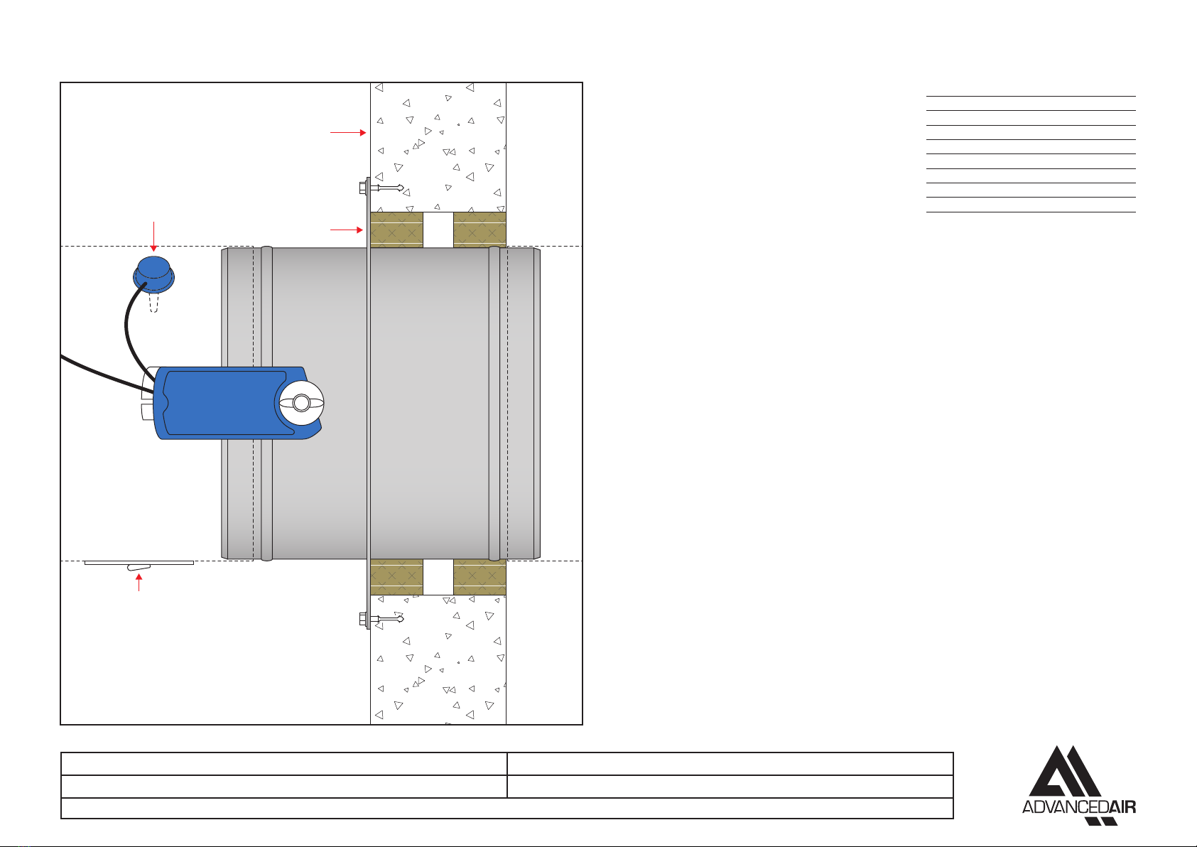
The 0400FME damper should only be commissioned once it is fully installed and connected to electrical
power. The damper should be inspected thoroughly to ensure that it is clean and free of any internal debris
before the damper actuation is tested as per the following instructions:
• Isolate the power.
• Remove the access door.
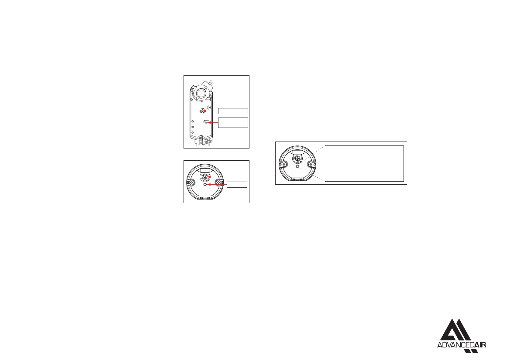
• Test the damper manually by using the Allen key provided and
turning it clockwise until the damper is fully opened, mechanically
lock the actuator by using a screwdriver to turn the STOP SHAFT 5.
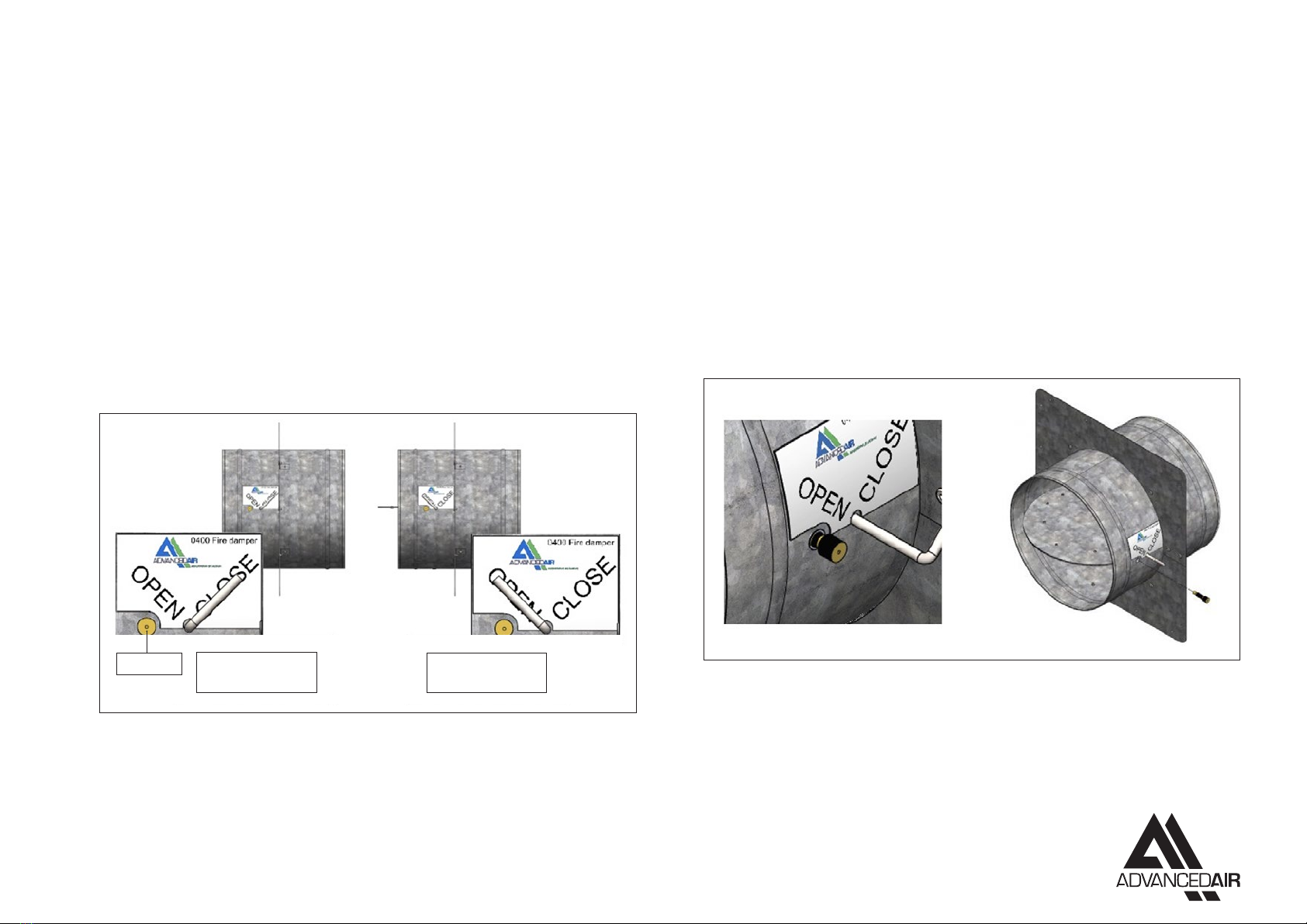
• Visually inspect the damper checking that the damper is in its fully
opened position.
• Close the damper by turning the Allen key clockwise and releasing
it, the spring action of the actuator will wind the damper to its fully
closed position.
• Visually inspect the damper checking that the damper is in its fully
closed position.
• Reapply power to the actuator. The actuator will start to travel, and
a GREEN light will be lit on the Thermal Release housing, it will take
90 seconds to fully open.
• The switch on the Thermal Release housing can be pressed to
simulate activation of the thermal release, the LED light will turn
RED and the actuator will spring return to its unpowered position,
it should take 15 seconds to complete this cycle.
• Release the switch and the damper will return to its fully opened
position.
• Visually inspect through the access door that the blades are fully
open and then re-fit the access door.
• Damper not fully opening or closing?
• Obstruction to the blades – remove the obstruction.
• Incorrect set up of the actuator – the actuator has been adjusted by others from the Factory Set
position.
• For other faults contact Advanced Air Sales Oce.
• Complete any relevant reports.
Maintenance
0400FME dampers are installed as a life safety product and it is essential that they are always maintained
so they are in a clean working condition. In accordance with BS9999 Annex W.1 maintenance and inspection
should be undertaken annually.
Maintain the dampers as follows;
• Remove the access door to internally inspect the damper.
• Visually inspect all damper components for signs of corrosion, obstructions and build-up of dirt/dust.
• Remove any obstructions, wipe away all dirt and dust from the damper blades and duct surfaces.
• Check that the thermal release probe is intact and does not show signs of damage.
• After internal inspections are complete a functional check of the damper should be made.
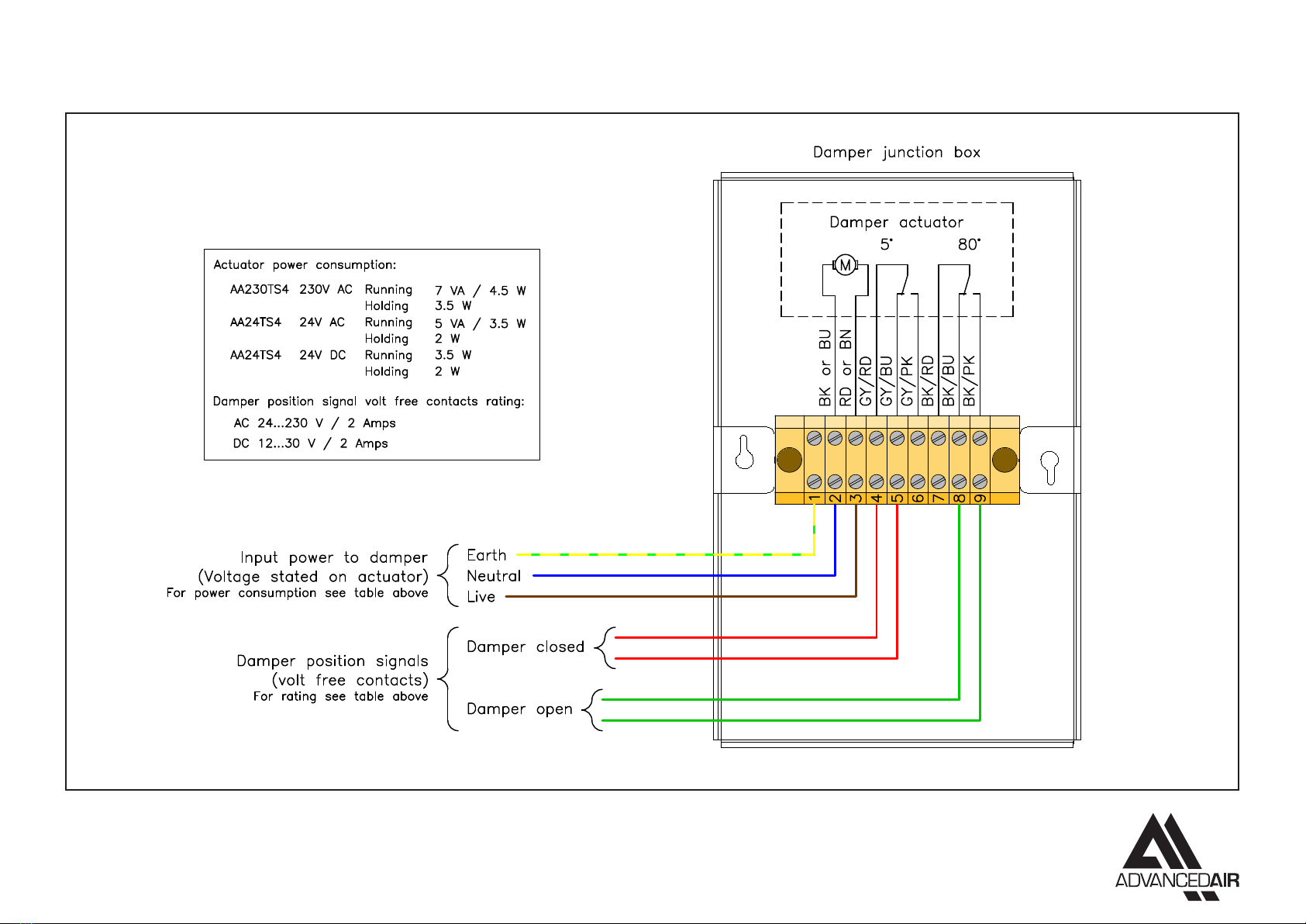
• The 0400FME damper is fitted with an electrical thermal release probe and its housing has a LED light
and an On/O toggle switch.
• A GREEN light indicates that there is a power supply and that the thermo sensor is OK.
• A RED light indicates a power supply but there is a fault.
• No light indicates that there is no power supply.
• Push and hold the toggle switch to simulate over-temperature. This simulates the response of the
thermal release, enabling the proper functioning test of the actuator and damper. It will take 15 seconds
for the damper to close and during the test the LED light will turn RED.
• After checking that the blades on the damper are fully closed, release the switch and the actuator will
power to its open position and the light will turn GREEN, check the blades are in the open position.
• Refit the access door and complete maintenance reports as appropriate.
0400FME OPERATION AND MAINTENANCE
LED Light
RED
Operating voltage OK. Thermo sensor defect.
GREEN
Operating voltage OK. Thermo sensor OK.
DARK
No operating voltage.
STOP SHAFT
– turn 5º
Allen key slot
Switch