Trox EK-JZ User manual

Smoke control damper
Type EK-JZ
Installation and operating manual
Read the instructions prior to performing any task!
according to EN12101-8
Declaration of performance DoP / EK-JZ / 003
GB/en

A00000062392, 5, GB/en
Translation of the original
© 2017
TROX GmbH
Heinrich-Trox-Platz
47504 Neukirchen-Vluyn, Germany
Germany
Phone: +49 (0) 2845 2020
Fax: +49 (0) 2845 202-265
E-mail: [email protected]
Internet: http://www.troxtechnik.com
07/2020
Smoke control damper Type EK-JZ
2

General information
About this manual
This operating and installation manual enables oper-
ating or service personnel to correctly install the TROX
product described below and to use it safely and effi-
ciently.
This operating and installation manual is intended for
use by fitting and installation companies, in-house tech-
nicians, technical staff, instructed persons, and qualified
electricians or air conditioning technicians.
It is essential that these individuals read and fully under-
stand this manual before starting any work. The basic
prerequisite for safe working is to comply with the safety
notes and all instructions in this manual.
The local regulations for health and safety at work and
general safety regulations also apply.
This manual must be given to the system owner when
handing over the system. The system owner must
include the manual with the system documentation. The
manual must be kept in a place that is accessible at all
times.
Illustrations in this manual are mainly for information
and may differ from the actual design.
Copyright
This document, including all illustrations, is protected by
copyright and pertains only to the corresponding
product.
Any use without our consent may be an infringement of
copyright, and the violator will be held liable for any
damage.
This applies in particular to:
Publishing content
Copying content
Translating content
Microcopying content
Saving content to electronic systems and editing it
TROX Technical Service
To ensure that your request is processed as quickly as
possible, please keep the following information ready:
Product name
TROX order number
Delivery date
Brief description of the fault
Online www.troxtechnik.com
Phone +49 2845 202-400
Limitation of liability
The information in this manual has been compiled with
reference to the applicable standards and guidelines,
the state of the art, and our expertise and experience of
many years.
The manufacturer does not accept any liability for dam-
ages resulting from:
Non-compliance with this manual
Incorrect use
Operation or handling by untrained individuals
Unauthorised modifications
Technical changes
Use of non-approved replacement parts
The actual scope of delivery may differ from the infor-
mation in this manual for bespoke constructions, addi-
tional order options or as a result of recent technical
changes.
The obligations agreed in the order, the general terms
and conditions, the manufacturer's terms of delivery,
and the legal regulations in effect at the time the con-
tract is signed shall apply.
We reserve the right to make technical changes.
Defects liability
For details regarding defects liability please refer to sec-
tion "VI. Warranty Claims" of the Delivery Terms of
TROX GmbH.
The General Delivery Terms of TROX GmbH can be
found on the Internet at www.trox.de.
General information
Smoke control damper Type EK-JZ 3
Safety notes
Symbols are used in this manual to alert readers to
areas of potential hazard. Signal words express the
degree of the hazard.
Comply with all safety instructions and proceed carefully
to avoid accidents, injuries and damage to property.
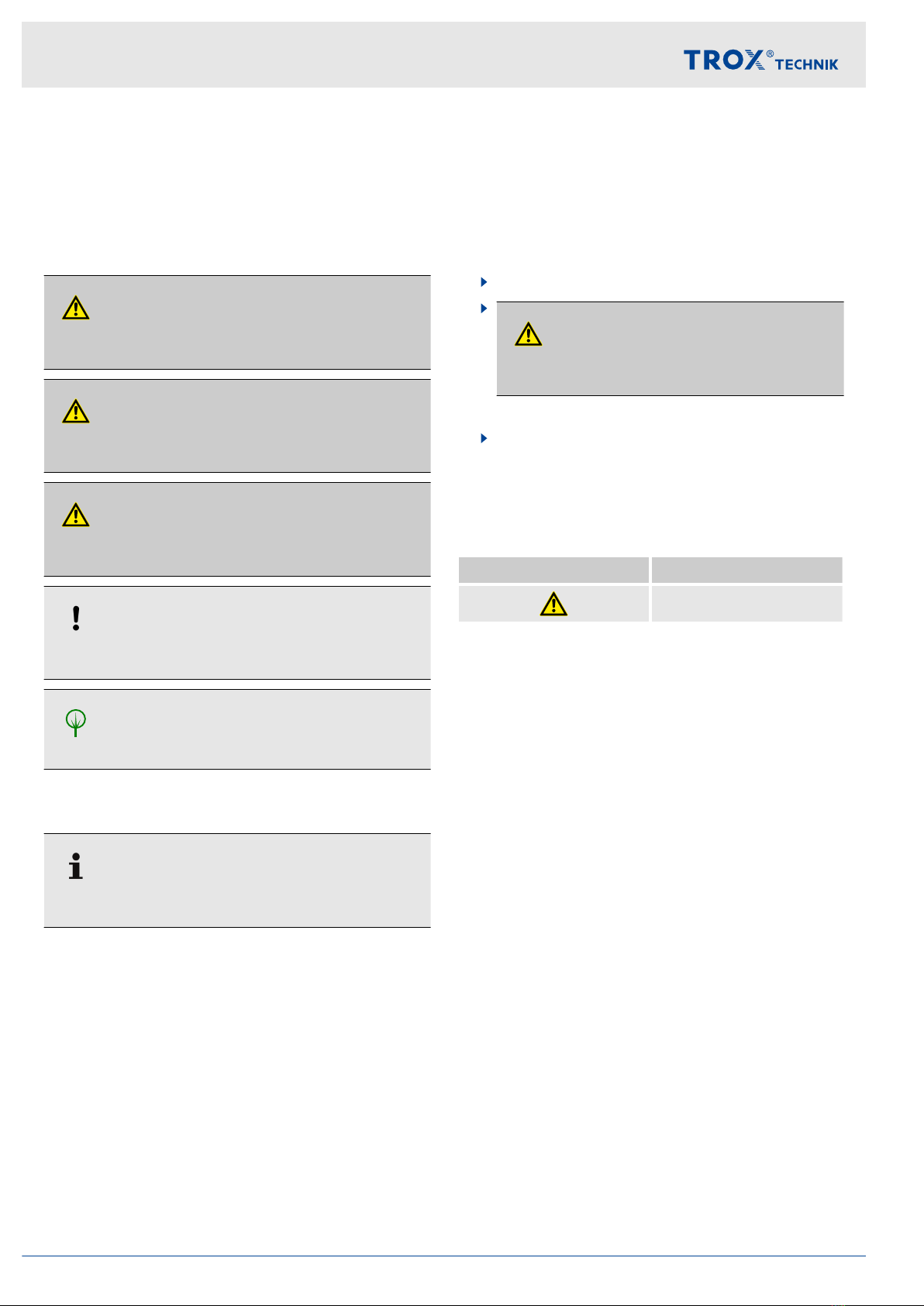
DANGER!
Imminently hazardous situation which, if not avoided,
will result in death or serious injury.
WARNING!
Potentially hazardous situation which, if not avoided,
may result in death or serious injury.
CAUTION!
Potentially hazardous situation which, if not avoided,
may result in minor or moderate injury.
NOTICE!
Potentially hazardous situation which, if not avoided,
may result in property damage.
ENVIRONMENT!
Environmental pollution hazard.
Tips and recommendations
Useful tips and recommendations as well as informa-
tion for efficient and fault-free operation.
Safety notes as part of instructions
Safety notes may refer to individual instructions. In this
case, safety notes will be included in the instructions
and hence facilitate following the instructions. The
above listed signal words will be used.
Example:
1. Loosen the screw.
2.
CAUTION!
Danger of finger entrapment when closing
the lid.
Be careful when closing the lid.
3. Tighten the screw.
Specific safety notes
The following symbols are used in safety notes to alert
you to specific hazards:
Warning signs Type of danger
Warning – danger zone.
General information
Smoke control damper Type EK-JZ4

1 Safety.................................................................. 6
1.1 General safety notes................................... 6
1.2 Correct use.................................................. 6
1.3 Qualified staff............................................... 6
2 Technical data.................................................... 7
2.1 General data................................................ 7
2.2 Dimensions and weight............................... 8
3 Transport and storage..................................... 10
4Parts and function........................................... 12
5 Installation........................................................ 13
5.1 Installation situations................................. 13
5.2 Safety notes regarding installation............ 14
5.3 General installation information................. 14
5.3.1 Installation materials .............................. 15
5.3.2 Fixing points........................................... 18
5.3.3 Adjoined damper installation.................. 19
5.4 Solid walls or solid shaft walls................... 20
5.4.1 Installation opening................................ 20
5.4.2 Installation type dry, mortarless / dry,
mortarless - mortar-based...................... 23
5.4.3 Installation type mortar-based / dry, mor-
tarless - mortar-based............................ 26
5.4.4 On solid external wall or solid shaft
wall......................................................... 32
5.4.5 Lift for fire and rescue service................ 34
5.5 Lightweight shaft wall................................ 36
5.6 Lightweight partition wall........................... 38
5.7 Solid ceiling slabs...................................... 40
5.7.1 Installation type, mortar-based............... 40
5.8 Fire-resistant smoke extract ducts............ 42
5.8.1 Installation on vertical smoke extract
ducts....................................................... 42
5.8.2 On a horizontal smoke extract duct........ 44
5.8.3 In a horizontal smoke extract duct.......... 46
5.8.4 At the end of a horizontal smoke extract
duct......................................................... 48
5.9 Suspending the smoke control damper..... 50
5.9.1 General................................................... 50
5.9.2 Fixing the unit to the ceiling slab............ 50
5.9.3 Suspended installation........................... 50
5.10 After installation....................................... 50
6 Smoke extract duct and cover grille.............. 51
6.1 Smoke extract ducts for multi compart-
ments......................................................... 51
6.2 Smoke extract duct for a single compart-
ment........................................................... 52
6.3 Inspection access...................................... 52
6.4 Cover grilles............................................... 53
6.4.1 Crimped wire mesh (A) and perforated
plate (B).................................................. 54
6.4.2 Aluminium grille with slanted blades (C,
D, E)....................................................... 55
7 Electrical connection...................................... 56
7.1 General safety notes................................. 56
7.2 Wiring and connection to the central
BMS........................................................... 56
7.3 Actuators B24 and B230........................... 57
7.4 Actuator with control module..................... 57
7.4.1 TROXNETCOM B24A, B24AM,
B24AS ................................................... 58
7.4.2 B24BKNE............................................... 59
7.4.3 SLC technology - B24C.......................... 60
7.4.4 B24D and B230D................................... 61
8 Commissioning/functional test...................... 63
8.1 Commissioning.......................................... 63
8.2 Functional test........................................... 63
9 Maintenance..................................................... 64
10 Decommissioning, removal and disposal..... 66
11 Index................................................................. 67
Table of contents
Smoke control damper Type EK-JZ 5

1 Safety
1.1 General safety notes
Sharp edges, sharp corners and thin sheet metal
parts
CAUTION!
Danger of injury from sharp edges, sharp cor-
ners and thin sheet metal parts!
Sharp edges, sharp corners and thin sheet metal
parts may cause cuts or grazes.
– Be careful when carrying out any work.
–Wear protective gloves, safety shoes and a hard
hat.
Electrical voltage
DANGER!
Danger of electric shock! Do not touch any live com-
ponents! Electrical equipment carries a dangerous
electrical voltage.
– Only skilled qualified electricians are allowed to
work on the electrical system.
–Switch off the power supply before working on
any electrical equipment.
1.2 Correct use
Type EK-JZ smoke control dampers are used in
smoke and heat exhaust systems to remove smoke
and heat. They may be used with the following sys-
tems:
– in pressurisation systems
– mechanical (i.e. powered) smoke exhaust sys-
tems
– natural smoke and heat exhaust systems
– heat exhaust systems
Operation of smoke control dampers is allowed only
in compliance with installation regulations and the
technical data in this installation and operating
manual.
Modifying the smoke control damper or using
replacement parts that have not been approved by
TROX is not permitted.
Incorrect use
WARNING!
Danger due to incorrect use!
Incorrect use of the smoke control damper can lead
to dangerous situations.
Never use the smoke control damper:
–in areas with potentially explosive atmospheres
– outdoors without sufficient protection against the
effects of weather
– in atmospheres where chemical reactions,
whether planned or unplanned, may cause
damage to the smoke control damper or lead to
corrosion
1.3 Qualified staff
WARNING!
Danger of injury due to insufficiently qualified
individuals!
Incorrect use may cause considerable injury or
damage to property.
– Only specialist personnel must carry out work.
Personnel:
Skilled qualified electrician
Specialist personnel
Skilled qualified electrician
Skilled qualified electricians are individuals who have
sufficient professional or technical training, knowledge
and actual experience to enable them to work on elec-
trical systems, understand any potential hazards related
to the work under consideration, and recognise and
avoid any risks involved.
Specialist personnel
Specialist personnel are individuals who have sufficient
professional or technical training, knowledge and actual
experience to enable them to carry out their assigned
duties, understand any potential hazards related to the
work under consideration, and recognise and avoid any
risks involved.
Safety
General safety notes
Smoke control damper Type EK-JZ6
2 Technical data
2.1 General data
Nominal sizes B x H 200 × 430 – 1200 × 2030 mm
Casing length 250 mm
Volume flow rate range up to 24361 l/s
up to 87700 m³/h
Differential pressure range Pressure level 2, -1000...500 Pa
Operating temperature -30 °C...50 °C the temperature should not fall below the dew
point
Upstream velocity ≤ 10 m/s with the maximum size
>10...15 m/s with smaller sizes, up to 87700 m³/h
Closed blade air leakage EN 1751, Class 3
Casing air leakage EN 1751, Class C
EC conformity EU Construction Products Regulation no. 305/2011
EN 12101-8 – Smoke and heat control systems –
Smoke control dampers
EN 1366-10 – Fire resistance tests for service installa-
tions – Smoke control dampers
EN 1366-2 – Fire resistance tests for service installa-
tions – Part 2: Fire dampers
EN 13501-4 – Fire classification of construction products
and building elements – Fire resistance tests on compo-
nents of smoke control
EN 1751 – Ventilation for buildings – Air terminal
devices
Declaration of performance DoP / EK-JZ / 003
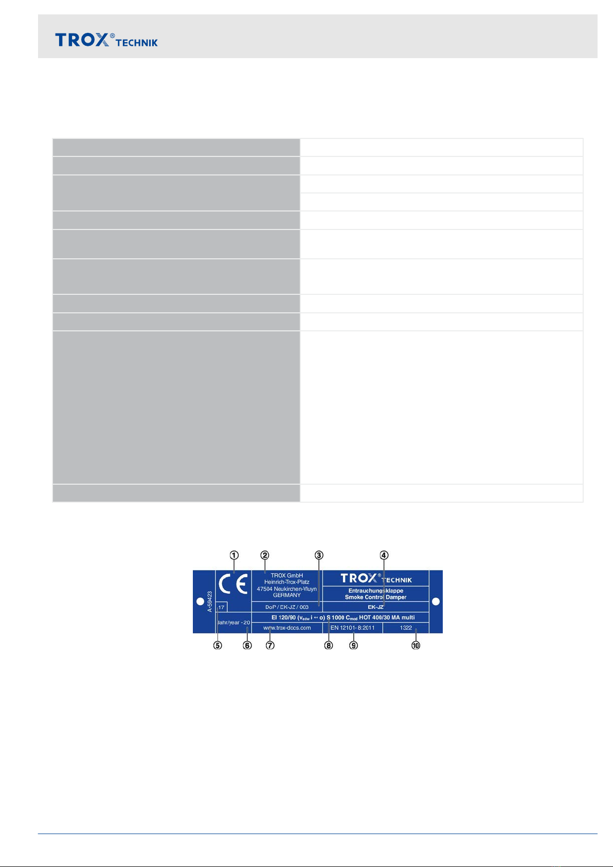
Rating plate
Fig. 1: Smoke control damper rating plate (example)
①CE mark
②Manufacturer's address
③No. of the declaration of performance
④Type
⑤The last two digits of the year in which the CE
marking was affixed
⑥Year of manufacture
⑦Website from which the DoP can be downloaded
⑧Regulated characteristics; the fire resistance class
depends on the application and may vary
⑨Number of the European standard and year of its
publication
⑩Notified body
Technical data
General data
Smoke control damper Type EK-JZ 7

2.2 Dimensions and weight
Fig. 2: EK-JZ
B x H = nominal size = area exposed to the airflow
①Connecting subframe for smoke extract duct
(steel, optional)
②Keep clear to provide access to the actuator
encasing
ⒶInstallation side
ⒷOperating side
Technical data
Dimensions and weight
Smoke control damper Type EK-JZ8

Dimensions [mm] Number
B H C Blades Handles
200..1200
(50 mm)
430 – 2 1
630 3 1
830 4 1
1030 5 1
1230 6 1
1430 550 7 2
1630 650 8 2
1830 9 2
2030 10 2
Weight [kg]
B
[mm]
H [mm]
430 630 830 1030 1230 1430 1630 1830 2030
200 29 37 46 54 62 71 79 87 95
250 31 39 48 56 65 73 82 91 99
300 32 41 50 59 67 76 85 94 103
350 33 43 53 61 70 79 88 98 107
400 35 44 54 63 73 82 92 101 111
450 36 46 56 66 75 85 95 105 114
500 38 48 58 68 78 88 98 108 118
550 39 50 61 70 81 91 101 112 122
600 41 51 62 73 83 94 105 115 126
650 42 53 64 75 86 97 108 119 130
700 44 55 66 77 89 100 111 122 134
750 45 57 69 80 91 103 114 126 137
800 47 58 70 82 94 106 118 129 141
850 48 60 72 84 97 109 121 133 145
900 49 62 75 87 99 112 124 136 149
950 51 64 77 89 102 115 127 140 153
1000 52 65 78 91 104 117 130 143 156
1050 54 67 80 94 107 120 134 147 160
1100 55 69 83 96 110 123 137 150 164
1150 57 71 85 98 112 126 140 154 168
1200 58 72 87 101 115 129 143 158 172
Technical data
Dimensions and weight
Smoke control damper Type EK-JZ 9
3 Transport and storage
Delivery check
Check delivered items immediately after arrival for
transport damage and completeness. In case of any
damage or an incomplete shipment, contact the ship-
ping company and your supplier immediately.
A complete shipment includes:
Smoke control damper(s)
– Attachments/accessories, if any
Installation and operating manual (one per ship-
ment)
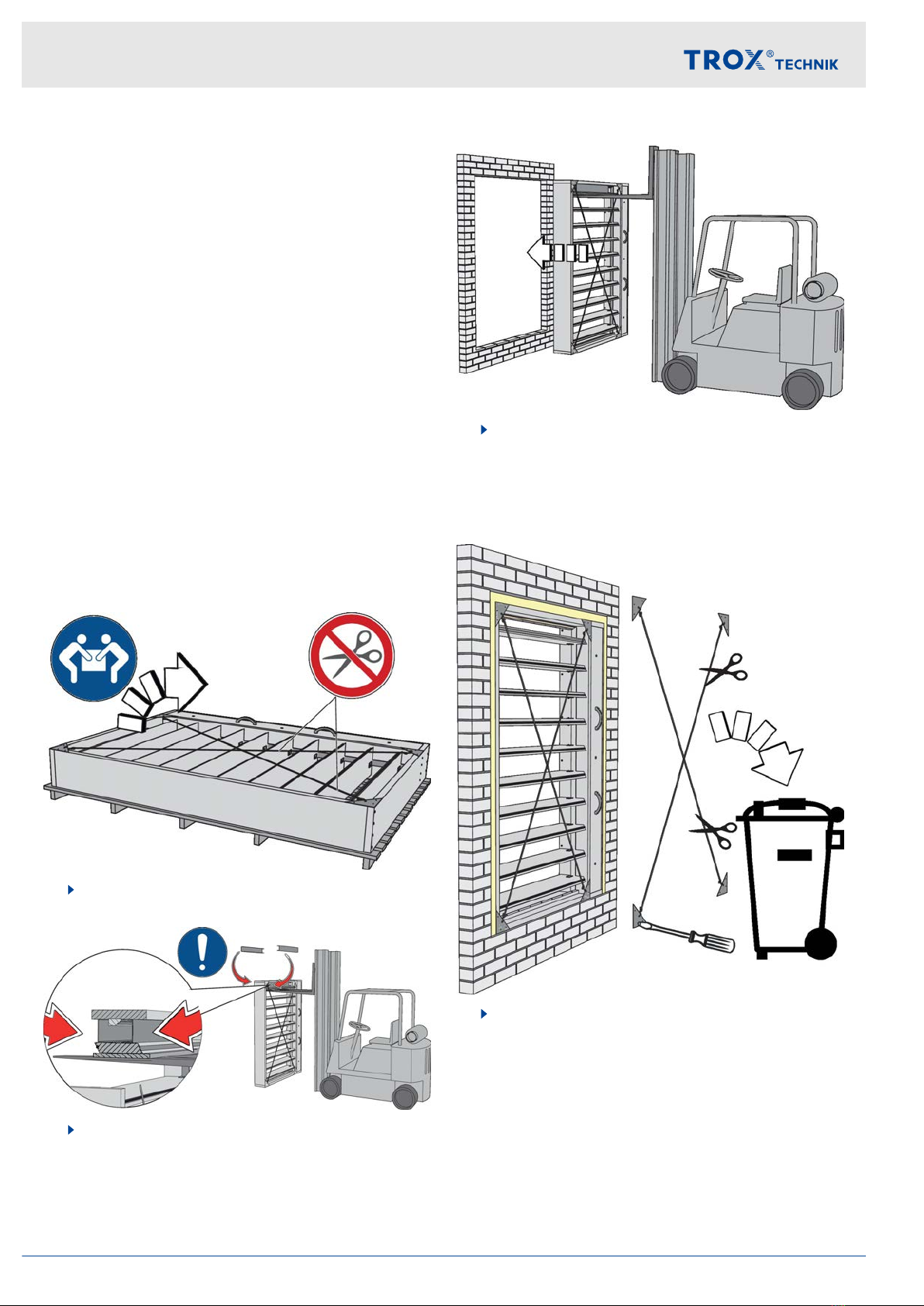
Transport on site
If possible, take the product in its transport packaging
up to the installation location.
Smaller dampers can be lifted and placed in the installa-
tion opening by two people. Ask someone to give you a
hand.
Dampers which are supplied with U channel sections as
a transport aid have to be moved with suitable lifting
equipment, e.g. a forklift truck.
1. Unpack the damper and place it upright on the
floor. Do not remove the straps yet.
2. Place the U channel sections between the upper-
most blade and the frame.
3. Move the fork carefully underneath the uppermost
blade, then lift it. Put a piece of wood or anything
similar between the blade and the fork so as not to
damage the blade.
Carefully lift the smoke control damper with the
forklift truck and place it in the installation opening.
4. Once you have installed the smoke control
damper, remove the straps; in case of mortar-
based installation, remove the straps only after the
mortar has cured. Remove the corner protectors.
Dispose of the straps and corner protectors.
Storage
For temporary storage please note:
Remove any plastic wrapping.
Protect the product from dust and contamination.
Transport and storage
Smoke control damper Type EK-JZ10

Store the product in a dry place and away from
direct sunlight.
Do not expose the unit to the effects of weather (not
even in its packaging).
Do not store the product below -30 °C or above 50
°C.
Packaging
Properly dispose of packaging material.
Transport and storage
Smoke control damper Type EK-JZ 11

4 Parts and function
Smoke control dampers are used in mechanical smoke
extract systems. They are used for extracting smoke
gases and for providing additional supply air to one or
more fire compartments.
Smoke control dampers are made from calcium silicate
boards, and the electric actuator and the optional con-
trol module are encased so that the functional reliability
is ensured even in the event of a fire.
Regular maintenance of the smoke control damper is
required to ensure its functional reliability
Ä
9 ‘Mainte-
nance’ on page 64.
Fig. 3: EK-JZ smoke control damper
①Casing
②Blades
③Blade tip seal (special profile seal)
④Side seal
⑤Travel stop, bottom
⑥Rating plate
⑦Actuator
⑧Cover fixing
⑨Linkage
⑩Actuator encasing
⑪Cover of the actuator encasing (sectional view)
⑫Handle (to remove the cover)
⑬Travel stop, top
Smoke extract
Fig. 4: Smoke extract system
①EK-JZ in a solid shaft wall
②EK-JZ in a solid wall and a duct
③EK-JZ on a solid shaft wall
④On a vertical smoke extract duct (shaft)
⑤On a horizontal smoke extract duct
⑥In a horizontal smoke extract duct
⑦At the end of a horizontal smoke extract duct
⑧EK-JZ as additional supply air inlet
⑨Cover grilles
During normal operation Type EK-JZ smoke control
dampers remain closed. For smoke extract, the smoke
control dampers in the affected fire compartment fully
open so that smoke can be extracted. All other smoke
control dampers remain closed.
In the event of a fire, smoke control dampers that are
used as additional supply air inlets in the affected fire
compartment also open so that smoke can be extracted.
To ensure the creation of a layer that is nearly free from
smoke, smoke control dampers used as additional
supply air inlets should be installed near the ground.
The control input signal for the actuator may come from
a duct smoke detector or from the central fire alarm
system. Using cables with specific circuit integrity for the
supply voltage ensures that the actuator is supplied with
voltage even in the event of a fire and hence that its
function and the communication are maintained.
Supply air and smoke extraction in ventilation sys-
tems
When authorised by building authorities or authorised
bodies, smoke extract and supply air applications as
well as ventilation can be enabled in combined systems
with smoke control dampers. Depending on the system
layout, the damper blade can be fully opened, fully
closed or in the intermediate position. Depending on
where the dampers are installed, country-specific regu-
lations may apply to ventilation applications.
Parts and function
Smoke control damper Type EK-JZ12

5 Installation
5.1 Installation situations
The table lists the various EK-JZ installation types; for details on the performance level see the declaration of per-
formance.
Installation locations described here may be combined with other installation location characteristics. For example, a
smoke control damper may be installed on a vertical smoke extract duct where a horizontal smoke extract duct
branches off.
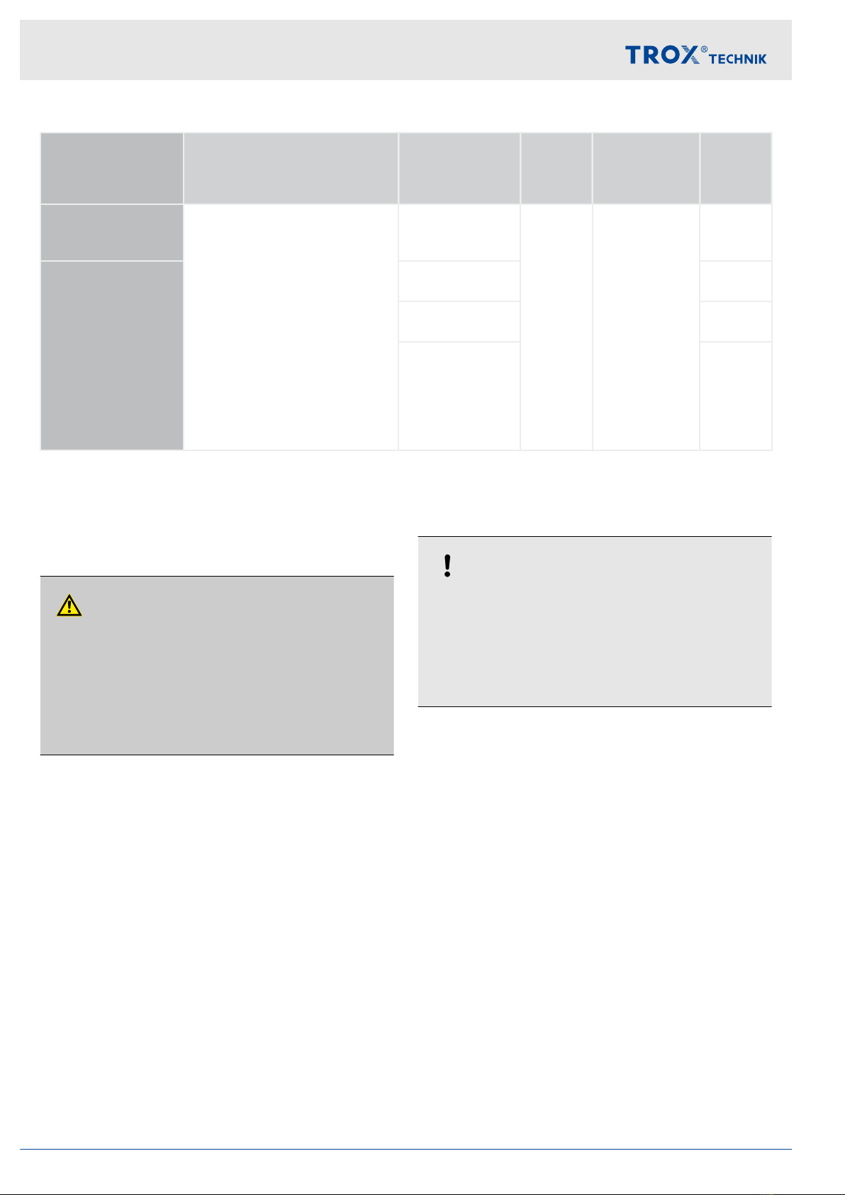
Supporting con-
struction
Construction Installation loca-
tion
Installa-
tion type
Performance
level
Installa-
tion
informa-
tion
Solid wall
Concrete, aerated concrete,
bricks
d ≥ 100 mm
ρ ≥ 500 kg/m3
Adjoined installation of two
dampers is possible
EN 1366-8 (smoke extract
ducts for multi compart-
ments can be used)
EN 1366-9 (smoke extract
ducts for single compart-
ments can be used)
In a solid wall
(wall is not part of
the smoke extract
duct)
NEI 120
(Vew, i↔o)
Ä
26
T / N EI 120
(Vew, i↔o)
Ä
23
TEI 90
(Vew, i↔o)
Solid shaft wall as
part of a smoke
extract duct
In a shaft wall
(the shaft is part
of a smoke
extract duct)
N
T;
N is pos-
sible on
one side EI 120
(Ved, i↔o)
Ä
23
On a shaft wall
(the shaft is part
of a smoke
extract duct)
T
Ä
32
Lightweight shaft
wall
Plasterboard fire barrier 2 x
20 mm
d ≥ 90 mm
In a shaft wall
(the shaft is part
of a smoke
extract duct)
T/N EI 90
(Vedw, i↔o)
Ä
36
Lightweight parti-
tion wall
Plasterboard fire barrier 2 x
12.5 mm
d ≥ 100 mm
In a lightweight
partition wall, the
wall is not part of
the smoke extract
duct
T/N EI 90
(Vew, i↔o)
Ä
38
Solid ceiling slabs
Concrete, aerated concrete
d ≥ 150 mm
ρ ≥ 550 kg/m3
EN 1366-8 (smoke extract
ducts for multi compart-
ments can be used)
EN 1366-9 (smoke extract
ducts for single compart-
ments can be used)
in solid ceiling
slab NEI 120
(how, i↔o)
T = dry mortarless installation, N = mortar-based installation, LE = as specified for the duct
Installation
Installation situations
Smoke control damper Type EK-JZ 13
Supporting con-
struction
Construction Installation loca-
tion
Installa-
tion type
Performance
level
Installa-
tion
informa-
tion
Fire-resistant ver-
tical smoke extract
duct
Firestop board (calcium sili-
cate)
d ≥ 35 mm
ρ ≥ 500 kg/m3
Perimeter strips (i.e. on four
sides)
Adjoined installation of two
dampers is possible
EN 1366-8 (smoke extract
ducts for multi compart-
ments can be used)
EN 1366-9 (smoke extract
ducts for single compart-
ments can be used)
on a vertical duct
LE EI 120
(Ved, i↔o)
Ä
42
Fire-resistant hori-
zontal smoke
extract duct
on a horizontal
duct
Ä
44
in a horizontal
duct
Ä
46
at the end of a
horizontal duct
Ä
48
T = dry mortarless installation, N = mortar-based installation, LE = as specified for the duct
5.2 Safety notes regarding installation
Sharp edges, sharp corners and thin sheet metal
parts
CAUTION!
Danger of injury from sharp edges, sharp cor-
ners and thin sheet metal parts!
Sharp edges, sharp corners and thin sheet metal
parts may cause cuts or grazes.
– Be careful when carrying out any work.
–Wear protective gloves, safety shoes and a hard
hat.
5.3 General installation information
NOTICE!
Be careful to not damage the smoke control
damper
– Protect the smoke control damper from contami-
nation and damage.
–Cover the flange openings and the actuator (e.g.
with plastic) to protect them from mortar and
dripping water.
Please note:
The smoke control damper has to be installed so
that the damper blade shaft is horizontal.
Smoke control damper and electric actuator
(encasing) must remain accessible for maintenance.
Make sure that no loads are imposed on the casing
as this may impair the function of the smoke control
damper.
Install the smoke control damper without torsion
(horizontal/vertical).
Mortar-based installation: The installation gap must
be large enough so that mortar can be filled in even
in case of thicker walls/ceilings.
Requirements for wall systems
EK-JZ smoke control dampers may be installed in wall
systems if these walls have been erected in compliance
with regulations and the manufacturers' instructions,
and if the information on the respective installation sit-
uation applies and the following requirements are met.
Provide any installation openings according to the
installation details in this manual.
Installation
Safety notes regarding installation
Smoke control damper Type EK-JZ14

Solid walls or solid shaft walls
Solid walls or solid shaft walls made of, for example,
concrete, aerated concrete or bricks, gross density
≥ 500 kg/m³.
Wall thickness W ≥ 100 mm.
Provide each installation opening according to the
local and structural conditions and with regard to the
dimensions of the smoke control damper.
Lightweight partition walls with metal support struc-
ture
Lightweight partition wall with metal support or steel
support structure, with European classification to
EN 13501-2 or equivalent national classification.
Cladding on both sides made from plasterboard fire
barriers.
Wall thickness W ≥ 100 mm.
≤ 625 mm distance between metal studs.
Create an installation opening with trimmers (studs
and noggings).
Trim panels and a support extension must be pro-
vided and screw-fixed to the support structure.
Additional layers of cladding (if stated in the usability
certificate for the wall) and double stud construc-
tions are approved.
Connect the metal sections near the installation
opening according to the installation details in this
manual.
Shaft walls with metal support structure
Shaft walls or additional leaves with metal support
structure or steel support structure, with European
classification to EN 13501-2 or equivalent national
classification.
Cladding on one side made from plasterboard fire
barriers.
Wall thickness W ≥ 90 mm (cladding according to
installation details).
≤ 625 mm distance between metal studs.
Be sure to follow the manufacturers' instructions for
the height, width and thickness of walls.
Create an installation opening with trimmers (studs
and noggings).
Trim panels and a support extension must be pro-
vided and screw-fixed to the support structure.
Ensure accessibility to the shaft from the rear.
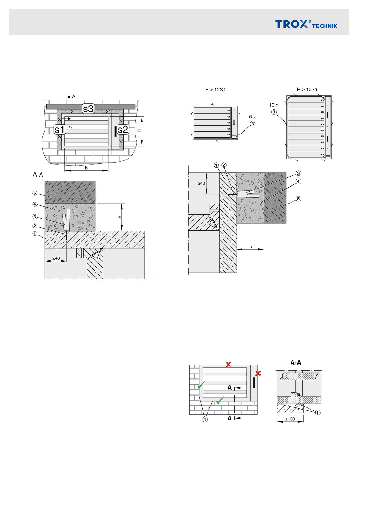
5.3.1 Installation materials
Mineral wool infill
Unless stated otherwise in the installation details, use
mineral wool with a gross density or compact density of
≥ 80 kg/m³ and a melting point of ≥ 1000 °C.
Fig. 5: Installation gap
①Wall
②Mineral wool
③Ablative coating (if required)
④EK-JZ
For a smooth look you can apply ablative coating of one
of the following types to the mineral wool in the installa-
tion gap:
Hilti:
–Ablative coating CFS-CT
Hensel:
– Ablative coating HENSOMASTIK 5 KS Farbe
Promat:
– Ablative coating Promastopp-CC
Acceptable mortars for mortar-based installation
In case of mortar-based installation, the open spaces
between the fire damper casing and the wall or ceiling
slab must be closed off with mortar. Entrapped air is to
be avoided. The mortar bed depth should be equal to
the thickness of the wall but must be at least 100 mm.
The following mortars are acceptable:
DIN 1053: Groups II, IIa, III, IIIa; fire protection
mortar of groups II, III
EN 998-2: Classes M 2.5 to M 10 or fire protection
mortar of classes M 2.5 to M 10
Equivalent mortars that meet the requirements of
the above standards, gypsum mortar or concrete
Installation
General installation information > Installation materials
Smoke control damper Type EK-JZ 15
Fixing tab for wall installation
With mortar bed widths of s ³40 mm, attach a fixing tab
to the damper frame and spread open prior to mortar-
fixing.
Fig. 6: EK-EU mortar-based installation with fixing tab
1 EK-JZ
2 Chipboard screw Æ3x25 mm (accessories)
3 Fixing tab (accessories)
4 Mortar bed
5 Solid shaft wall or solid wall
s Mortar bed width (installation gap)
The fixing tab is not needed if the installation of the
damper is partly dry and mortarless and there is a screw
connection in the installation gap S1 and S3.
Fixing tab for ceiling slab installation
Before the subframe is mortared in, the fixing tabs on
the damper frame must be bent and spread.
Fig. 7: EK-EU mortar-based installation with fixing tab
1 EK-JZ
2 Chipboard screw Æ3x25 mm (accessories)
3 Fixing tab (accessories)
4 Mortar bed
5 Solid ceiling slab
s Mortar bed width (installation gap)
High-temperature sealing tape
Fig. 8: Affix the sealing tape
Affix the high-temperature sealing tape (Fig. 8/1) with
trim panel thickness (flush at front and rear) to the
damper frame (if necessary, mark the trim panel thick-
ness beforehand). Do not glue the ceramic fibre
paper onto the wall or trim.
Installation
General installation information > Installation materials
Smoke control damper Type EK-JZ16

Permitted use (depending on installation situation)
Lower damper frame
Damper frame on non-drive side
The high-temperature sealing tape (melting point
1200 °C) is – unless otherwise agreed – included in the
supply package.
Impregnation and coating
Impregnation (included in the supply package unless
otherwise agreed) or coating of the smoke control
damper for colour adjustment is acceptable if:
Mass per unit area ≤ 1.0 kg/m²
or thickness ≤ 0.5 mm
Apply only to calcium silicate surfaces, never to a
seal
Impregnation
–Promat GmbH - Impregnation 2000
– Promat GmbH - SR Impregnation
– Promat GmbH - Tunnel Impregnation
Coating
– Commercially available emulsion paint
Installation
General installation information > Installation materials
Smoke control damper Type EK-JZ 17
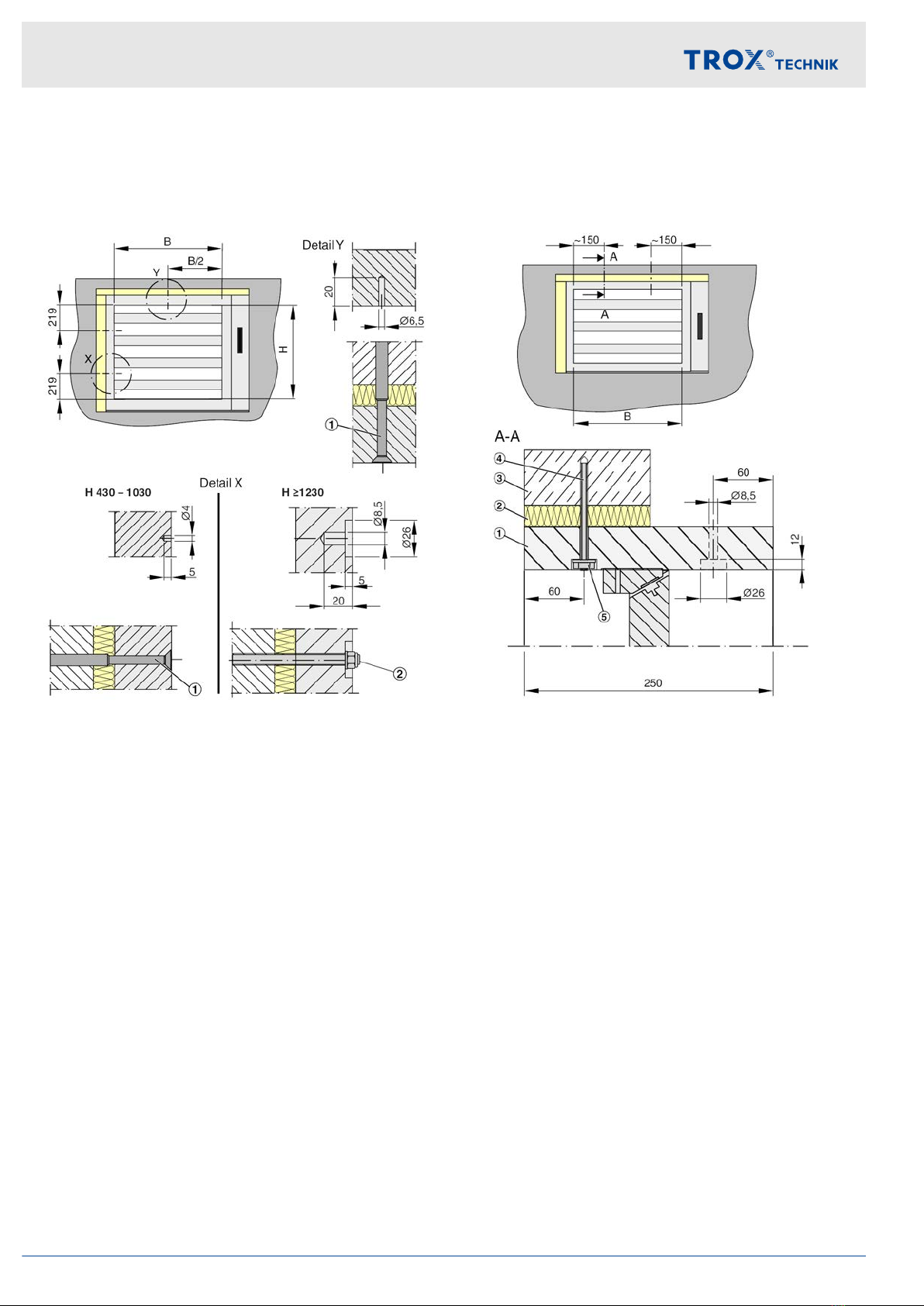
5.3.2 Fixing points
The frame of the smoke control damper has pre-drilled
connection points that are used to screw-fix the damper
to the wall.
Fig. 9: EK-EU pre-drilled attachment options
1 e.g. concrete screw with countersunk head
2 Threaded bolts with nut and washer M8
Note: The fixing elements must not protrude on the
inside of the damper frame. Contact with the damper
blade will damage the damper blade and the entire
damper will need to be replaced.
Additional fixing points
If the pre-drilled fixing points cannot be used or addi-
tional drilled holes are needed, these must be provided
as follows in the damper frame.
Fig. 10: Create additional fixing options
1 EK-JZ
2 Mineral wool or high-temperature sealing tape
3 Solid shaft wall or solid wall
4 Wallplug with fire safety engineering certification
and threaded bolts M8
5 Washer, nut M8
Number of fixing points
B < 800 mm - 1 fixing point
B ³ 800 mm - 2 fixing points
Note: The fixing elements must not protrude on the
inside of the damper frame. Contact with the damper
blade will damage the damper blade and the entire
damper will need to be replaced.
Installation
General installation information > Fixing points
Smoke control damper Type EK-JZ18

5.3.3 Adjoined damper installation
Side by side
The vertical frame section opposite the actuator
encasing has markings that indicate where the screw
holes to join dampers have to be drilled. If additional or
alternative fixing points are required, these must be pro-
vided as described under
Ä
5.3.2 ‘Fixing points’
on page 18.
Fig. 11: EK-JZ dampers side by side (left side construc-
tion and right side construction)
1 Dry wall screw 4.5 x 70 mm or 5.0 x 70 mm
2 Hexagon head screw M8 x 90 mm or threaded rod
M8 with washers and nuts
On top of each other
Screws can be set anywhere on the horizontal frame
sections; leave approx. 200 mm between screws,
approx. 40 mm between screws and edges; predrill
holes if necessary. Insert screws both from the top
damper and from the bottom damper; do not insert all
screws in one line, but in an offset pattern.
Fig. 12: EK-JZ dampers on top of each other (right side
construction)
1 Dry wall screw 4.5 x 70 mm or 5.0 x 70 mm
If you need more than two dampers sidy by side or on
top of each other, consult with TROX to determine if this
is technically feasible.
Installation
General installation information > Adjoined damper installation
Smoke control damper Type EK-JZ 19
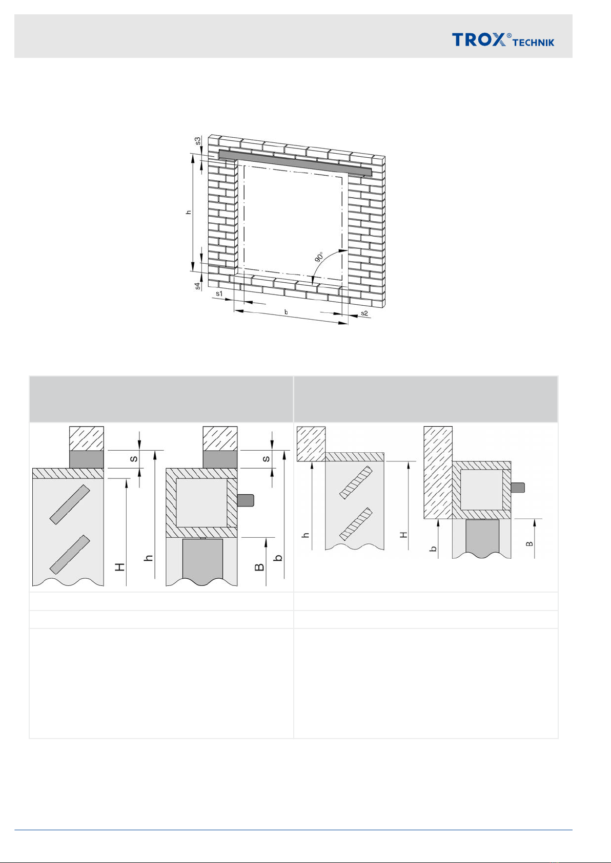
5.4 Solid walls or solid shaft walls
5.4.1 Installation opening
Fig. 13: Ideal installation opening
in
solid wall or shaft wall
on
solid wall, shaft wall or fire-resistant smoke extract
duct
b = [B + 280 mm] + s1 + s2 b = nominal width B
h = [H + 80 mm] + s3 + s4 h = nominal height H
b / h= [nominal size B / H + damper casing] + installation
gap
The installation gap (s) is dependent on the filling mate-
rial used:
Fibre paper: 3-5 mm
Mortar: up to 150 mm
Mineral wool: 10 to 40 mm
Ideally, the installation opening is equal to the nominal
size of the smoke control damper. For installation on a
wall, however, the installation opening may also be
smaller than the nominal size of the damper, for
example, when no damper standard height fits the instal-
lation opening exactly. In such a case you have to make
sure that there is enough clearance to install the
damper.
Installation
Solid walls or solid shaft walls > Installation opening
Smoke control damper Type EK-JZ20
Other manuals for EK-JZ
1
Table of contents
Other Trox Fire And Smoke Damper manuals


Popular Fire And Smoke Damper manuals by other brands

ETS NORD
ETS NORD NORDfire SEDM-L manual

Honeywell Home
Honeywell Home TrueZONE ARD Series installation instructions

Greenheck
Greenheck FD150X Installation, operation and maintenance instructions

Lindab
Lindab RECTANGULAR Series Installation booklet

System air
System air FDR-3G EX Series Handbook

Rf-t
Rf-t CR120 user manual

System air
System air PKIR-E60S Installation, operation and maintenance instructions

Greenheck
Greenheck FSD Series Installation instruction supplement

Mandik
Mandik SEDS-R manual

Swegon
Swegon actionair DWFX-F installation guide

klimaoprema
klimaoprema FDSD product manual

HVC
HVC NCA 700 Series Operation and maintenance manual


