Power Fist 8913295 User manual
V4.0 8913295
Please read and understand all instructions before use. Retain this manual for
future reference.
User Manual
4 to 21 in.
Portable Tire Changer

8913295 4 to 21 in. Portable Tire Changer V4.0
2 For technical questions call 1-800-665-8685
SPECIFICATIONS
Length
50 in.
Tire Size
4 to 21 in.
Number of Pieces
5
Socket Size
1 in.
Socket Type
Slip-Fit
Material
Steel
Post Diameter
Small
1/2 and 5/8 in.
Large
3/4 and 1 in.
SAFETY
WARNING! Read and understand all instructions before using this tool. The
operator must follow basic precautions to reduce the risk of personal injury
and/or damage to the equipment.
Keep this manual for safety warnings, precautions, operating or inspection and
maintenance instructions.
HAZARD DEFINITIONS
Please familiarize yourself with the hazard notices found in this manual. A notice
is an alert that there is a possibility of property damage, injury or death if certain
instructions are not followed.
DANGER! This notice indicates an immediate and specific hazard that will
result in severe personal injury or death if the proper precautions
are not taken.
WARNING! This notice indicates a specific hazard or unsafe practice that
could result in severe personal injury or death if the proper
precautions are not taken.
4 to 21 in.
Portable Tire Changer

V4.0 4 to 21 in. Portable Tire Changer 8913295
Visit www.princessauto.com for more information 3
CAUTION! This notice indicates a potentially hazardous situation that may result
in minor or moderate injury if proper practices are not taken.
NOTICE! This notice indicates that a specific hazard or unsafe practice will
result in equipment or property damage, but not personal injury.
WORK AREA
1. Operate in a safe work environment. Keep your work area clean, well-lit
and free of distractions. Place lights so you are not working in a shadow.
2. Keep anyone not wearing the appropriate safety equipment away from the
work area.
3. Store unused tools properly in a safe and dry location to prevent rust or
damage. Lock tools away and keep out of the reach of children.
PERSONAL SAFETY
WARNING! Wear personal protective equipment approved by the Canadian
Standards Association (CSA) or American National Standards Institute (ANSI).
PERSONAL PROTECTIVE EQUIPMENT
1. Always wear impact safety goggles that provide front and side protection
for the eyes. Eye protection equipment should comply with CSA Z94.3-07
or ANSI Z87.1 standards based on the type of work performed.
2. Wear gloves that provide protection based on the work materials or to
reduce the effects of tool vibration.
3. Wear protective clothing designed for the work environment and tool.
4. Non-skid footwear is recommended to maintain footing and balance in the
work environment.
5. Wear steel toe footwear or steel toe caps to prevent a foot injury from
falling objects.
PERSONAL PRECAUTIONS
Control the tool, personal movement and the work environment to avoid
personal injury or damage to tool.
1. Do not operate any tool when tired or under the influence of drugs, alcohol
or medications.

8913295 4 to 21 in. Portable Tire Changer V4.0
4 For technical questions call 1-800-665-8685
2. Avoid wearing clothes or jewelry that can become entangled with the
moving parts of a tool. Keep long hair covered or bound.
3. Do not overreach when operating a tool. Proper footing and balance
enables better control in unexpected situations.
SPECIFIC SAFETY PRECAUTIONS
WARNING! DO NOT let comfort or familiarity with product (gained from
repeated use) replace strict adherence to the tool safety rules. If you use
this tool unsafely or incorrectly, you can suffer serious personal injury.
1. Use the correct tool for the job. This tool was designed for a specific function.
Do not modify or alter this tool or use it for an unintended purpose.
2. Do not use the tool if any parts are damage broken or misplaced. Repair or
replace the parts.
3. Ensure that the tire and rim size match exactly. Attempting to inflate a tire
and rim that are mismatched can result in serious injury or death.
4. Ensure that the tire and wheel are free of wear or defects before using this tool.
5. Do not increase air pressure over 40 PSI during bead seating.
6. Do not exceed the tire manufacturer’s recommended pressure rating.
7. Ensure that the tire changer is secured on a flat, level, and sturdy surface
capable of supporting its weight and the weight of any additional
equipment needed for the job.
8. Do not stand on the tire changer. Serious injury may result if the tire
changer tips over.
UNPACKING
WARNING! Do not operate the tool if any part is missing. Replace the
missing part before operating. Failure to do so could result in a malfunction
and personal injury.
Remove the parts and accessories from the packaging and inspect for damage.
Make sure that all items in the parts list are included.

V4.0 4 to 21 in. Portable Tire Changer 8913295
Visit www.princessauto.com for more information 5
ASSEMBLY & INSTALLATION
Numbered references in parenthesis (#1) refer to the included Parts List
ASSEMBLE THE TIRE CHANGER
Consult the Parts Breakdown section when following the assembly instructions.
1. Place the main stand base (#4) on a level floor to prevent it from tipping
over during assembly.
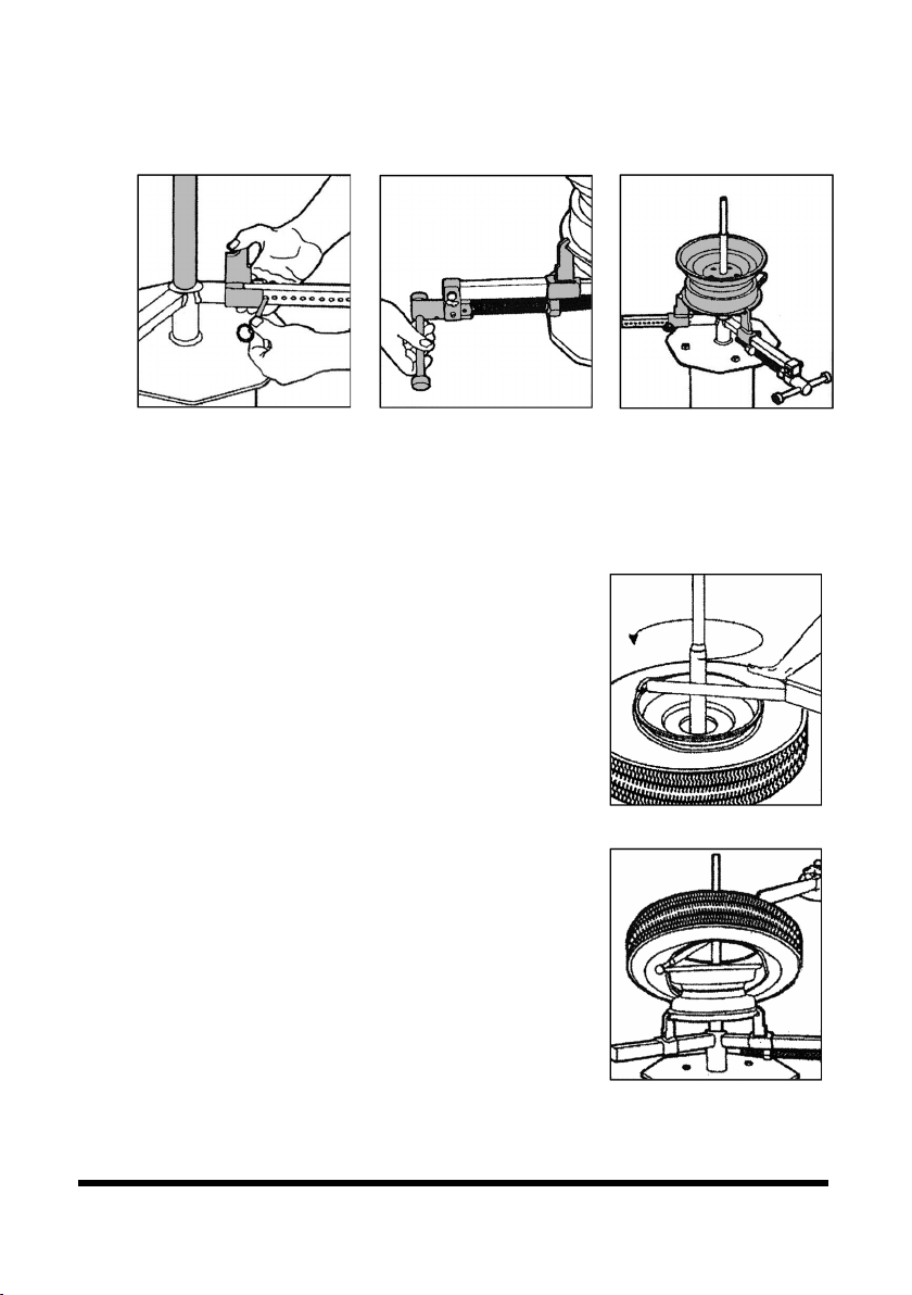
2. Position the jaw frame spider’s plate (#18), so the bolt holes align with the
main stand plate’s bolt holes (Fig. 1).
3. Insert an M12 x 30 bolt (#21) through each set of bolt holes. Slide a
washer and lock washer (#22) over the protruding bolts and secure each
bolt with an M12 Lock nut (#9). Tighten all nuts until the lock washer is
slightly compressed (Fig. 1).
4. The bead breaker receiver (#7) has three sets of bolt holes, two set on one
side of the flange and a single set on the other end. Insert the single set
end into the main stand bases’ bracket and align the bolt holes (Fig. 2).
a. Choose the bracket bolt holes that are appropriate for the tire size you
wish to demount.
5. Insert the Ø12 Lock Pin (#8) through the bracket and receiver bolt holes
(Fig. 2).
6. Insert the open end of the bead breaker foot (#5) over the bead breaker
receiver flange and align the bolt holes. Make sure the foot is facing away
from the base. Insert an M12x65 bolt (#6) through the bolt holes and
secure with an M12 Locknut (#9) (Fig. 3).
7. Insert the bead breaker tube (#10) into the receiver and align with either
the outer or innermost bolt holes. Insert an M10x55 bolt through the bolt
holes and secure with an M10 lock nut (#12) (Fig. 4).
8. Slide a fixed jaw clamp (#19) onto both jaw frame spiders (#18). The hook
must face inward. Insert a lock pin Ø8 (#20) behind each jaw clamp.
9. Place the large and small posts (#2 and 3) into angled holder on the main
stand base. Place the tire bead tool (#1) in the other holder.

8913295 4 to 21 in. Portable Tire Changer V4.0
6 For technical questions call 1-800-665-8685
MOUNTING TO A CEMENT FLOOR
Make sure there is a minimum of 3 feet of working space on all sides of the tire
changer before mounting to the floor.
1. Always mount the tire changer to a concrete floor in an area that is well lit,
has adequate workspace and is away from areas of high foot traffic.
2. Ensure that the concrete floor is at least 4 in. in depth before mounting.
3. With at least one other person assisting you, move the tire changer to the
desired location.
4. Use the 1/2 in. holes at the base as a template for the holes to be drilled in
the floor.
WARNING! Do not use a concrete drill bit larger than 1/2 in. in diameter.
Larger holes may greatly reduce stability during operation.
5. Mark the location of the holes to be drilled and move the tire changer out
of the way.
6. Drill four holes in the concrete floor equal to the length of four 3 x 1/2 in.
cement anchors (not included). The cement anchors will be used to secure
the tire changer to the floor.
7. Blow out the dust from the newly drilled holes.
8. Align the mounting holes at the base of the tire changer with the holes in
the floor surface. It may be necessary to level the tire changer with a
carpenter’s level and steel shims (not included).
9. Use a hammer to tap the cement anchors through the mounting holes on
the base of the tire changer and into the drilled holes in the floor until the
washer is flush with the base of the tire changer.
Fig. 1
Fig. 2
Fig. 3
Fig. 4

V4.0 4 to 21 in. Portable Tire Changer 8913295
Visit www.princessauto.com for more information 7
10. Tighten the nuts of the cement anchors firmly to secure the tire changer
in place.
OPERATION
BEAD BREAKING
Lubricate the breaker handles before breaking the bead to avoid wear and tear.
1. Completely deflate the tire. Remove the valve
stem core to speed up this process.
2. Place the tire rim on the base’s triangular
wedge to hold it in place.
3. Set the bead breaker foot (#5) against the
edge of the tire’s rim.
a. It may be necessary to adjust the height
of the bead breaker receiver by
removing the lock pin (#8), adjusting the
receiver location in the bracket and
reinserting the lock pin.
4. Push down on the handle (#11) to separate the bead from the rim.
5. If the bead does not come off all at once, it may be necessary to turn the
tire and repeat the procedure in several locations. You may be able to push
down with your hands or feet to complete the bead separation.
6. Turn the tire over and repeat the above steps.
CLAMPING THE TIRE RIM
1. Adjust each fixed jaw clamp so it is approximately the correct distance to
accommodate the rim (Fig. 6).
2. Place the rim onto the fixed jaw so it rests in the hooks. The tire stem
should be on the topside.
3. Hold the rim up and turn the T-handle (#13) until the moveable jaw clamp
(#17) is resting against the rim (Fig. 7).
4. Insert either the small (#2) or large post (#3) into the receiver at the center
of the spider arms. Each post has two diameters (see Specifications). Use
the post that is appropriate for wheel’s axle opening.
Fig. 5
8913295 4 to 21 in. Portable Tire Changer V4.0
8 For technical questions call 1-800-665-8685
5. Tighten the moveable jaw clamp to secure the rim in place (Fig. 8). The tire
will still be on the rim. It is not in the image for clarity.
DEMOUNTING AND MOUNTING TIRES
The tire bead tool has a demounting head with the knob parallel to the tool and
a mounting head with the knob at a 90º angle to the tool.
1. Apply a lubricant made for rubber along the bead
to ease the process of demounting the tire.
2. Insert the tire bead tool’s (#1) demounting head
beneath the top bead (Fig. 9).
3. Stand on the opposite side of the tire. Press the
tire bead tool down until it is flat across the tire
and touching the post. The bead will slide up and
over the rim.
4. Keep the tool flat and use the center post as a
fulcrum point. Work the tool around the tire
while keeping the knob under the bead and raise
the bead above the upper rim.
5. Apply the lubricant to the lower tire bead. Repeat
step 2 to 4 to lift the lower bead above the upper
rim (Fig. 10).
6. Repair the tire or use a new tire.
7. Lubricate both tire beads. Do not use a spray or
allow the lubricant into the tire.
8. Hook the bar’s mounting end onto the rim. There is an indentation that fits
over the rim’s edge. Push the lower bead over the vertical portion of the hook.
Fig. 6
Fig. 8
Fig. 7
Fig. 9
Fig. 10
V4.0 4 to 21 in. Portable Tire Changer 8913295
Visit www.princessauto.com for more information 9
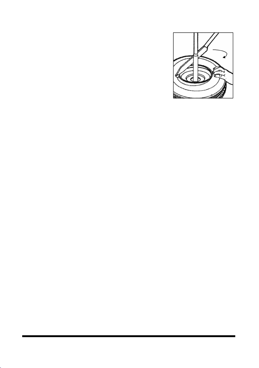
9. Press the tire down so some of the tire’s bead is
below the rim to help keep the tire from rotating.
This should be behind the direction you will turn
the bar (Fig. 11).
10. Press down on the tire with one hand and pull
the tire tool clockwise around the rim until the
bead mounts on the rim. Use the center post as
a fulcrum.
11. Repeat steps 11 to 13 with the upper bead.
ATV TIRES
ATV tires are more difficult to mount and demount due to their small diameter
and softness.
1. If the shoe slides off of the tire, hold the shoe in place and break the bead
slower than usual.
2. Use a generous amount of lubricant between the tire and the rim to make
the mounting and demounting easier.
INFLATING THE TIRES
WARNING! Do not overinflate tires. Overinflating poses a risk of explosion. Always
use a pressure gauge (not included) to check tire pressure during inflation.
Inflate the tire to the recommended pressure to ensure the beads are properly
set. The tire walls may pop into shape due to the air pressure. Lift the tire if the
bead is not sealing.
You may need to spread a thick layer of grease along the bead to form a seal. Only
use a grease that does not degrade rubber. As the tire inflates, the grease is forced
out. Remove the grease and store it in a container for other use. Wipe the
remaining grease off the tire and rim.
CARE & MAINTENANCE
1. Maintain the tool with care. A tool in good condition is efficient, easier to
control and will have fewer problems.
2. Inspect the tool components periodically. Repair or replace damaged or
worn components. Only use identical replacement parts when servicing.
Fig. 11

8913295 4 to 21 in. Portable Tire Changer V4.0
10 For technical questions call 1-800-665-8685
3. Keep the tool handles clean, dry and free from oil/grease at all times.
4. Maintain the tool’s labels and name plates. These carry important information.
If unreadable or missing, contact Princess Auto Ltd. for replacements.
WARNING! Only qualified service personnel should repair the tool. An
improperly repaired tool may present a hazard to the user and/or others.
LUBRICATION
Inspect and lubricate the tool when required. Only use light oil to lubricate the
tool. Other lubricants may not be suitable and could damage the tool or cause a
malfunction during use.
STORAGE
When not in use for an extended period, apply a thin coat of lubricant to the
steel parts to avoid rust. Remove the lubricant before using the tool again.
DISPOSAL
Recycle a tool damaged beyond repair at the appropriate facility.
TROUBLESHOOTING
Visit a Princess Auto Ltd. location for a solution if the tool does not function
properly or parts are missing. If unable to do so, have a qualified technician
service the tool.

V4.0 4 to 21 in. Portable Tire Changer 8913295
Visit www.princessauto.com for more information 11
PARTS BREAKDOWN
PARTS LIST
# DESCRIPTION QTY
1
Tire Bead Tool
1
2 Small Post 1
3 Large Post 1
4 Main Stand Base 1
5 Bead Breaker Foot 1
6 Bolt, M12 x 65 1
7
Bead Breaker Receiver
1
8 Lock Pin Ø12 1
9 Lock Nut M12 5
10 Bead Breaker Tube 1
11 Bead Breaker Handle 1
12 Lock Nut M10 4
13 T-Handle 1

8913295 4 to 21 in. Portable Tire Changer V4.0
12 For technical questions call 1-800-665-8685
14
Threaded Rod Assembly
1
15 Bolt, M10 x 45 1
16 End Cap 3
17 Movable Jaw Clamp 1
18 Jaw Frame Spider 3
19 Fixed Jaw Clamp 2
20
Lock Pin Ø8
2
21 Bolt, M12 x 30 4
22 Flat Washer and
Lock Washer Ø12
4
23 Bolt, M10 x 55 1
24
Pin Ø6 x 22
2

V4.0 4 to 21 in. Portable Tire Changer 8913295
Visit www.princessauto.com for more information 13

8913295 4 to 21 in. Portable Tire Changer V4.0
14 For technical questions call 1-800-665-8685

V 4,0 8913295
Vous devez lire et comprendre toutes les instructions avant d'utiliser l'appareil.
Conservez ce manuel afin de pouvoir le consulter plus tard.
Manuel d'utilisateur
Machine à changer les
pneus portative, 4 à 21 po

8913295 Machine à changer les pneus portative, 4 à 21 po V 4,0
2 En cas de questions techniques, appelez le 1-800-665-8685
SPÉCIFICATIONS
Longueur 50 po
Taille de pneu 4 à 21 po
Nombre de pièces
5
Taille de douille 1 po
Type de douille Réglage coulissant
Matériau Acier
Diamètre du poteau Petit 1/2 et 5/8 po
Grand 3/4 et 1 po
SÉCURITÉ
AVERTISSEMENT ! Veuillez lire et comprendre toutes les instructions avant
d'utiliser cet outil. L'utilisateur doit respecter les précautions de base
lorsqu'il utilise cet outil afin de réduire le risque de blessure ou de
dommage à l'équipement.
Conservez ce manuel qui contient les avertissements de sécurité, les
précautions, les instructions de fonctionnement ou d'inspection et d'entretien.
DÉFINITIONS DE DANGER
Veuillez-vous familiariser avec les avis de danger qui sont présentés dans ce
manuel. Un avis est une alerte indiquant qu'il existe un risque de dommage à la
propriété, de blessure ou de décès si on ne respecte pas certaines instructions.
DANGER ! Cet avis indique un risque immédiat et particulier qui
entraînera des blessures corporelles graves ou même la
mort si on omet de prendre les précautions nécessaires.
Machine à changer les
pneus portative, 4 à 21 po

V 4,0 Machine à changer les pneus portative, 4 à 21 po 8913295
Visitez www.princessauto.com pour plus d'informations 3
AVERTISSEMENT ! Cet avis indique un risque particulier ou une pratique non
sécuritaire qui pourrait entraîner des blessures
corporelles graves ou même la mort si on omet de
prendre les précautions nécessaires.
ATTENTION ! Cet avis indique une situation possiblement dangereuse qui
peut entraîner des blessures mineures ou modérées si on
ne procède pas de la façon recommandée.
AVIS ! Cet avis indique un risque particulier ou une pratique non
sécuritaire qui entraînera des dommages au niveau de
l'équipement ou des biens, mais non des blessures corporelles.
AIRE DE TRAVAIL
1. Travaillez dans un environnement de travail sécuritaire. Gardez votre aire
de travail propre, bien éclairée et exempte de toute distraction. Placez les
lampes de façon à ne pas travailler dans l’ombre.
2. Assurez-vous que les personnes qui ne portent pas l'équipement de
sécurité approprié ne se trouvent pas à proximité de l'aire de travail.
3. Rangez les outils correctement dans un lieu sécurisé et sec. Gardez les
outils hors de la portée des enfants.
SÉCURITÉ PERSONNELLE
AVERTISSEMENT ! Portez de l'équipement de protection personnelle
homologué par l'Association canadienne de normalisation (CSA) ou
l'American National Standards Institute (ANSI).
ÉQUIPEMENT DE PROTECTION PERSONNELLE
1. Portez toujours des lunettes antiprojections qui offrent une protection
frontale et latérale pour les yeux. L'équipement de protection des yeux
devrait être conforme à la norme CSA Z94.3-07 ou ANSI Z87.1 fonction du
type de travail effectué.
2. Portez des gants qui protègent en fonction des matériaux de travail et pour
réduire les effets des vibrations de l'outil.
3. Portez des vêtements de protection conçus pour l'environnement de travail
et pour l'outil.

8913295 Machine à changer les pneus portative, 4 à 21 po V 4,0
4 En cas de questions techniques, appelez le 1-800-665-8685
4. Les chaussures antidérapantes sont recommandées pour maintenir la
stabilité et l'équilibre au sein de l'environnement de travail.
5. Portez des chaussures à embout d'acier ou à coquilles d'acier pour éviter
les blessures aux pieds dues à la chute d'objets.
PRÉCAUTIONS PERSONNELLES
Gardez le contrôle de l'outil, de vos mouvements et de l'environnement de
travail pour éviter les blessures ou le bris de l'outil.
1. N'utilisez pas l'outil si vous êtes fatigué ou sous l'effet de drogues, d'alcool
ou de médicaments.
2. Évitez de porter des vêtements ou des bijoux pouvant se prendre dans les pièces
mobiles d'un outil. Gardez les cheveux longs recouverts ou attachés.
3. N'utilisez pas l'outil si vous devez étirer les bras pour vous en servir. Une
stabilité et un équilibre appropriés sont nécessaires afin d'avoir un meilleur
contrôle en cas de situations inattendues.
CONSIGNES DE SÉCURITÉ SPÉCIFIQUES
AVERTISSEMENT! Ne permettez PAS au confort ou à votre familiarisation
avec l'outil (obtenus après un emploi répété) de se substituer à une
adhésion stricte aux règles de sécurité de l'outil. Si vous utilisez cet outil
de façon dangereuse ou incorrecte, vous pouvez subir des blessures
corporelles graves.
1. Utilisez le bon outil pour la tâche à effectuer. Cet outil a été conçu pour une
utilisation spécifique. Évitez de modifier ou d'altérer cet outil ou de l'utiliser
à une fin autre que celle pour laquelle il a été conçu.
2. N’utilisez pas l’outil si des pièces présentent des dommages ou sont
déplacées. Réparez ou remplacez les pièces.
3. Assurez-vous que la taille du pneu et de la jante correspondent
exactement. Une tentative de gonfler un pneu qui ne correspond pas à la
jante pourrait entraîner des blessures graves ou même la mort.
4. Assurez-vous que le pneu et la roue sont sans usure et n’ont aucun défaut
avant d’utiliser cet outil.
5. Ne dépassez pas la pression d’air de plus de 40 lb/po carré pendant le
talonnage.

V 4,0 Machine à changer les pneus portative, 4 à 21 po 8913295
Visitez www.princessauto.com pour plus d'informations 5
6. Ne dépassez pas la pression d’air nominale recommandée par le fabricant.
7. Assurez-vous que la machine à changer les pneus est sécurisée sur une
surface plane, solide et de niveau, capable de supporter son poids et celui
de tout outil et équipement additionnels requis pour l’opération.
8. Ne vous tenez pas sur la machine à changer les pneus. Il y a un risque de
blessures graves si la machine se renverse.
DÉBALLAGE
AVERTISSEMENT ! Ne faites pas fonctionner l'outil si des pièces sont
manquantes. Remplacez les pièces manquantes avant l'utilisation. Le
non-respect de cet avertissement peut entraîner une défectuosité et des
blessures graves.
Retirez les pièces et les accessoires de l'emballage et vérifiez s'il y a des
dommages. Assurez-vous que tous les articles sur la liste de pièces sont compris.
ASSEMBLAGE ET INSTALLATION
Les numéros de référence entre parenthèses (no1) se rapportent à la liste de
pièces comprise.
ASSEMBLAGE DE LA MACHINE À CHANGER LES
PNEUS
Consultez la section consacrée à la répartition des pièces en suivant les
instructions de montage.
1. Placez la base de support principale (no 4) sur une surface plane pour
éviter tout basculement lors de l’assemblage.
2. Positionnez la plaque du croisillon de cadre de mâchoire (no 18) pour que
les trous de boulon soient alignés avec les trous de boulon de la plaque de
support principale (fig. 1).
3. Insérez un boulon M12 x 30 (no 21) dans chaque paire de trous de boulon.
Glissez une rondelle et une rondelle-frein (no 22) sur les boulons en saillie
et fixez chaque boulon au moyen d’un contre-écrou M12 (no 9). Serrez
tous les écrous jusqu’à ce que la rondelle-frein soit légèrement comprimée
(fig. 1).

8913295 Machine à changer les pneus portative, 4 à 21 po V 4,0
6 En cas de questions techniques, appelez le 1-800-665-8685
4. Le récepteur du décolleur de talon (no 7) est muni de trois paires de trous
de boulon, soit deux paires sur un côté de la bride et une paire sur l’autre
extrémité. Insérez l’extrémité ayant une seule paire dans le support de la
base de support principale et alignez les trous de boulon (fig. 2).
a. Choisissez les trous de boulon de support correspondant à la taille du
pneu à démonter.
5. Insérez la goupille de sécurité Ø12 (no 8) à travers le support et les trous
de boulon du récepteur (fig. 2).
6. Insérez l’extrémité ouverte du pied du décolleur de talon (no 5) sur la bride
du récepteur du décolleur de talon et alignez les trous de boulon. Assurez-
vous que le pied est orienté dans le sens contraire à la base. Insérez un
boulon M12 x 65 (no 6) à travers les trous de boulon et fixez-le au moyen
d’un contre-écrou M12 (no 9) (fig. 3).
7. Insérez le tube du décolleur de talon (no 10) dans le récepteur et alignez-le
avec les trous de boulon extérieurs ou intérieurs. Insérez un boulon M10 x
55 dans les trous de boulon et fixez-le au moyen d’un contre-écrou M10
(no 12) (fig. 4).
8. Faites glisser un support fixe (no 19) sur les croisillons de cadre de
mâchoire (no 18). Le crochet doit être orienté vers l’intérieur. Insérez une
goupille de sécurité Ø8 (no 20) derrière chaque support.
9. Placez les montants, grand et petit (no 2 et no 3), dans le support incliné
sur la base de support principale. Placez l’outil de talon (no 1) dans l’autre
support.
Fig. 1
Fig. 2
Fig. 3
Fig. 4
Table of contents
Languages:
Popular Tyre Changer manuals by other brands


Corghi
Corghi A 9824 TI Operator's manual

SICE
SICE S 100 PL instruction manual

Aston Global
Aston Global ATC-5800 Installation, Operation and Maintenance User’s Manual

Ranger
Ranger R76LT Installation and operation manual

Snap-On
Snap-On EEWH331A Operation instructions

Corghi
Corghi Artiglio Master 28 Operator's manual


