Power Hawk P-16X User manual

THE POWER HAWK®P-16X™ RESCUE SYSTEM
®
™
USER SAFETY & INSTRUCTION MANUAL
POWER HAWK

Power Hawk®P-16X™Rescue System Instruction Manual Page 1 of 27
™
®
1. GENERAL SAFETY INFORMATION ......................................................................................... 3
2. MANUFACTUER CONTACT INFORMATION............................................................................ 4
3. INTRODUCTION AND SYSTEM DESCRIPTION....................................................................... 6
3.1 THE P-16X™ RESCUE TOOL ............................................................................................................6
4. PREPARATION FOR OPERATION........................................................................................... 6
4.1 INSPECTION.......................................................................................................................................6
4.2 POWER SOURCE SELECTION AND CONNECTIONS.....................................................................7
4.2.1 PWR-LI12X “LI-GHTNING POWER PACK™”, 12V LITHIUM-ION........................................................8
4.2.2 BC-LI12X BATTERY CHARGER.........................................................................................................10
4.2.3 PA-12X POWER ADAPTER, 12V........................................................................................................11
4.3 AUXILLIARY & BACK-UP 12V POWER ..........................................................................................12
4.3.1 JC4-16 JUMPER CABLES ..................................................................................................................12
4.3.2 VH4-4 VEHICLE HARNESS WITH EC4-16 EXTENSION CABLE ......................................................12
5. TOOL ATTACHMENT SELECTION AND INSTALLATION ...................................................... 13
5.1 INSTALLING P-16X™ TOOL ATTACHMENT(S)..............................................................................13
5.2 INSTALLING SPREADER ARMS .....................................................................................................14
5.3 INSTALLING CUTTER ATTACHMENTS..........................................................................................14
5.4 REMOVING P-16X™ TOOL ATTACHMENTS .................................................................................16
6. POWERHEAD 70VARIABLE POSITIONING......................................................................... 17
7. OPERATION of P-16X™ RESCUE SYSTEM .......................................................................... 18
7.1 HAND-HELD OPERATIONS.............................................................................................................18
7.2 REMOTE OPERATIONS...................................................................................................................19
7.3 OPERATING SAFETY INFORMATION............................................................................................20
7.4 HELPFUL HINTS...............................................................................................................................20
8. MAINTENANCE for P-16X™ RESCUE SYSTEM .................................................................... 22
8.1 MAINTENANCE AFTER USE:..........................................................................................................22
8.2 MONTHLY MAINTENANCE AND INSPECTION:.............................................................................22
8.3 ANNUAL INSPECTION:....................................................................................................................22
8.4 STORAGE: ........................................................................................................................................23
8.5 STOP SCREW REPLACEMENT: .....................................................................................................23
8.6 REPLACEMENT PARTS...................................................................................................................23
8.7 TROUBLESHOOTING ......................................................................................................................23
9. SPECIFICATIONS................................................................................................................... 24
10. WARRANTY INFORMATION................................................................................................... 26
11. MAINTENANCE SERVICE RECORD...................................................................................... 27
TABLE OF CONTENTS

Power Hawk®P-16X™Rescue System Instruction Manual Page 2 of 27
™
®
THIS PAGE INTENTIONALLY LEFT BLANK

Power Hawk®P-16X™Rescue System Instruction Manual Page 3 of 27
™
®
1. GENERAL SAFETY INFORMATION
The Power Hawk®P-16X™ Rescue System is designed to provide safe operation. All users should read and be
thoroughly familiar with the operating instructions and safety precautions contained in this manual. Operator safety
depends on users being properly trained by the Authority having jurisdiction and using the tool for the purpose
intended. The following safety precautions must be observed at all times. FAILURE TO DO SO COULD RESULT
IN SERIOUS PERSONAL INJURY AND/OR DAMAGE TO PROPERTY AND/OR EQUIPMENT.
•The Power Hawk®P-16X™Rescue System shall only be operated by persons authorized by the
Authority having jurisdiction.
•Suitable protective equipment shall be worn as directed by the Authority having jurisdiction. At a
minimum, this should include gloves, helmet, eye protection, and body protection –such as turnout gear.
•Prior to use, inspect all Power Hawk®P-16X™ Rescue System components for any signs of damage or
fraying. Do not use damaged equipment.
•Stay alert. Do not operate tool when tired.
•Use only Power Hawk Technologies Authorized Service Centers and parts.
•This equipment should only be used with accessories approved by Power Hawk Technologies.
•Use of unauthorized accessories can result in unpredictable and unreliable product operation and is
therefore prohibited.
•Never use the tool while holding the cutting or spreading attachments. Hold the tool only by the handles
when operating. To avoid risk of serious personal injury and/or damage to property and/or equipment, do
not under any circumstances place hands or other body parts on or near Power Hawk® attachments when
in operation.
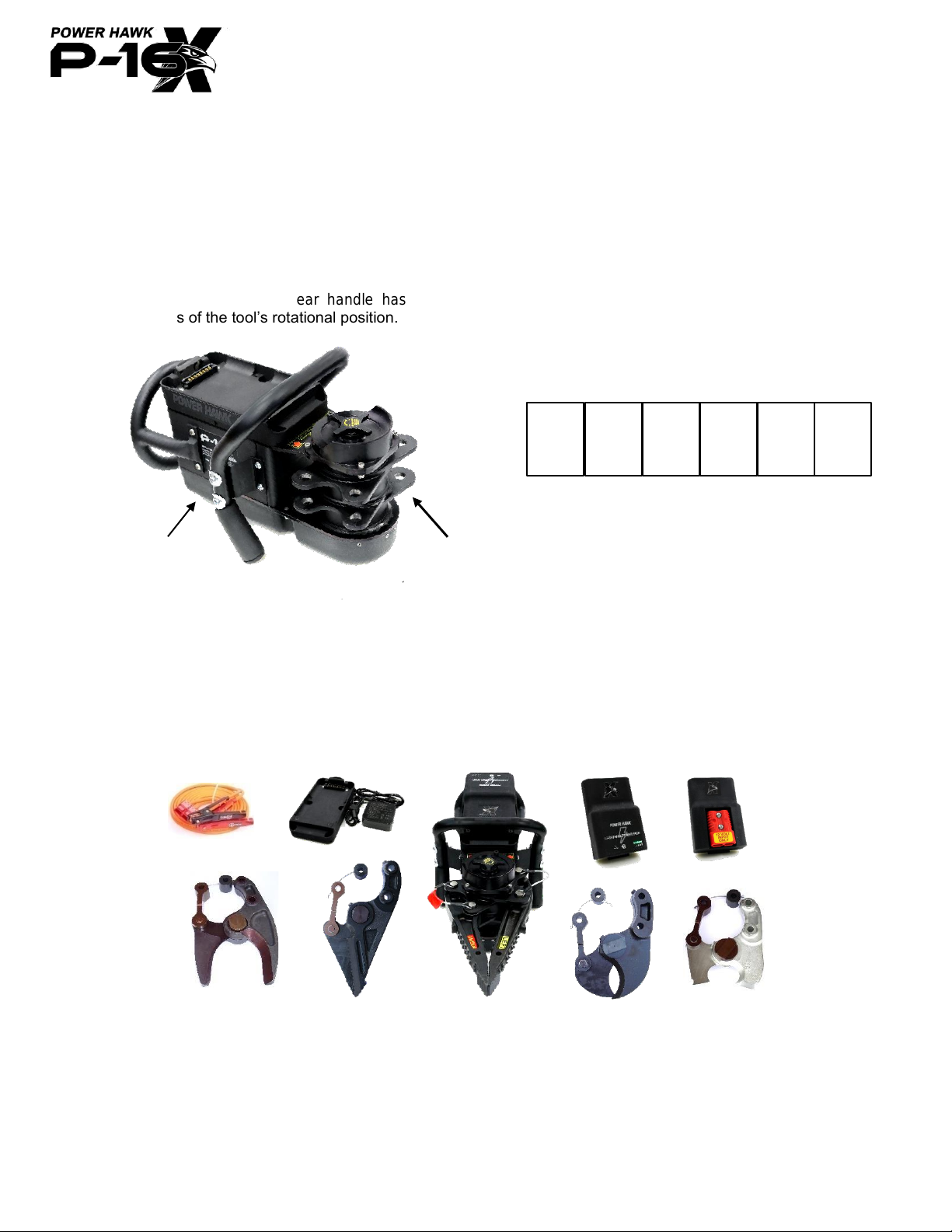
•Operate the tool only with the clutch knob tightened. The clutch is intended to secure the position of the
attachments. Failure to do so may result in personal injury due to sudden movement of the tool and/or
attachments.
•When spreading with Power Hawk® spreader attachments, make sure objects being spread are stabilized
and operator(s) and patient(s) are shielded from any loose debris.
•When stabilizing, use proper cribbing methods.
•Power Hawk® cutter attachments are designed to cut a variety of materials such as door and windshield
posts, pipe, sheet metal, steel plate, rebar, etc. Do not attempt to cut hardened metal, such as steering
columns, Nader pins, seat belt bolts, lock hasps, etc., as this action may result in blade damage.
•When cutting with the Power Hawk® cutting attachments, make sure the object being cut is anchored on
both sides and the tool is held firmly.
•Make sure the cutter Bolt and Nut is tight. The blades should never be able to be opened and closed by
hand. If tightening is required, the cutter nut should be torqued to 150 footpounds
•Make sure the cutter-link snap rings are secure.
•When cutting, position the cutter so that the material being cut does not wedge in between and cause the
blades to separate while cutting. Failure to do so may result in component breakage, causing serious
personal injury and/or damage to property and/or equipment.

Power Hawk®P-16X™Rescue System Instruction Manual Page 4 of 27
™
®
BATTERY AND BATTERY CHARGING SAFETY INFORMATION
All batteries contain corrosive acids and produce explosive gases during recharging. Failure to follow the safety
precautions below may result in acid burns and/or gas explosion, causing blindness, serious personal injury,
and/or damage to property and/or equipment.
•RECHARGE PWR-Li12X Battery Pack using ONLY the special charger Model BC-Li12X
provided by POWER HAWK Technologies, Inc.
•RECHARGE battery pack ONLY at temperatures between -13 to 131°F (-25 to 55°C)
•DO NOT expose battery pack to temperatures above 140°F (60°C)
•DO NOT use battery pack below -22°F (-30°C), if cold-soaked for 2 hours or more
•DO NOT store battery pack in a discharged state
•DO NOT attempt to open or service the battery pack
•DO NOT use battery pack for jump starting another battery
•DO NOT crush or puncture battery pack
•DO NOT submerge battery pack in water
•DO NOT expose battery pack to fire or excessive heat
•Keep battery pack and charger away from children
•TRANSPORTATION of Lithium-Ion batteries must be in accordance with U.S. DOT Hazardous Material
Regulations and International Dangerous Goods Regulations.
•DISPOSE of battery pack in accordance with Local, State, & Federal Laws and Regulations. They must
be collected, recycled, or disposed of in an environmentally sound manner. It is unlawful to incinerate
batteries, or discard them in municipal solid waste or landfill.
2. MANUFACTUER CONTACT INFORMATION
Power Hawk Technologies, Inc.,
300 Forge Way, Suite 2
Rockaway, New Jersey 07866 USA
Telephone: 973-627-4646 or 1-800-PWR-HAWK (1-800-797-4295)
Fax: 973-627-4622
www.powerhawk.com

Power Hawk®P-16X™Rescue System Instruction Manual Page 5 of 27
™
®
THIS PAGE INTENTIONALLY LEFT BLANK

Power Hawk®P-16X™Rescue System Instruction Manual Page 6 of 27
™
®
3. INTRODUCTION AND SYSTEM DESCRIPTION
3.1 THE P-16X™ RESCUE TOOL
The Power Hawk®P-16X™ Rescue Tool is a self-contained cordless tool that utilizes aerospace gear
technology, namely the Curtiss Wright Power Hinge, to deliver high output forces to tool attachments such as
spreaders and cutters. Tool attachments are quickly interchangeable using high-strength steel, ball detent pins.
A variable 70articulation of the power head and attachments allows greater versatility of access as compared
to conventional hydraulic rescue tools. The P-16X™ Rescue Tool is powered solely by 12 volts DC. There are
NO HYDRAULICS. The rear handle has a circular design to maintain identical trigger switch operation
regardless of the tool’s rotational position.
4. PREPARATION FOR OPERATION
4.1 INSPECTION
Remove P-16X™ Rescue System components and carefully inspect contents for any
damage. If damage is found, contact your local Power Hawk®Dealer or the Factory for
instructions.
Serial Number
Power head
A. P-16X™ Rescue Tool
B. AP-1600 Attach. Pin Set
C. PWR-Li12X “Li-GHTNING POWER PACK”, 12V
D. BC-Li12X Battery Charger
E. PA-12X Power Adapter
F. S-1601X Spreader Arms
A
C
D
E
B
B
H
I
J
F
K
G
G. CS-1602LW Power Blade
H. C-1601 Curved Cutter
I. C-1603 Hatchet Cutter
J. C-1604 Shredder Cutter
K. JC4-16 Jumper Cables
Enter the Serial Number of your P-16X™Rescue Tool below:
The five-digit number can be found on the right
side of the tool or on the bottom plate behind
the Power Head, as shown on the left.
X

Power Hawk®P-16X™Rescue System Instruction Manual Page 7 of 27
™
®
4.2 POWER SOURCE SELECTION AND CONNECTIONS
The Power Hawk®P-16X™ Rescue Tool is powered using 12 volts DC which must be connected via Power
Pack or Power Adapter. Power sources may include:
It is recommended that back-up 12 volts DC power always be available on-scene when using
the Power Hawk®P-16X™ Rescue System, especially when operating with consumable power
sources such as the Power Hawk power packs.
NOTE
The 12 volts DC power source must be capable of delivering sufficient current to properly operate
the P-16X™ Rescue Tool without causing damage to the power source itself.
(See section 9. SPECIFICATIONS for P-16X™ current requirements.)
VH4-4
Vehicle
Harness
with
EC4-16
Extension
Cable
•Direct 12 VDC vehicle
system hook-up
•Jumper Cable to
12 VDC batteries
JC4-16
Jumper
Cables
•Power Hawk
Power Packs
PWR-Li12X
Rechargeable
Lithium-Ion
PA-12X
Power Adapter
•12 VDC Generator
•12 VDC Converted Power Supply

Power Hawk®P-16X™Rescue System Instruction Manual Page 8 of 27
™
®
4.2.1 PWR-Li12X “Li-GHTNING POWER PACK™”, 12V Lithium-Ion
The PWR-Li12X “Li-GHTNING POWER PACK™” is a lightweight and portable 7.5
Ampere Hour (99WH) 13.2 V Lithium-Ion (LiFePO4) battery pack. The PWR-Li12X
uses a custom connector and a replaceable latch mechanism to connect power to the
internal controller of the P-16X™. A charge indicator using five (5) GREEN LEDs with
test button and fault indication are built into the Power Pack so that the user can
visually check the charge state of the battery. The PWR-Li12X “Li-GHTNING
POWER PACK™” charges via the same custom connector and latch mechanism
using the required battery charger -- Model BC-Li12X -- provided by POWER HAWK
Technologies, Inc. (See section 4.2.3 BC-Li12X BATTERY CHARGER.)
CAUTION
Prior to charging, inspect battery connection port to ensure no dirt/debris/corrosion will
block the connection. If there is corrosion, please contact Power Hawk.
Prior to selecting the PWR-Li12X Li-GHTNING Power Pack, note the charge
condition of the battery by PRESSING the “T” test button located on the top of
the pack. A fully charged battery is indicated by all five (5) GREEN LEDs
illuminating and the bar graphics directly underneath. As the charge on the
battery is depleted, the LED lights from right to left will not illuminate, indicating
reduced battery capacity.
IMPORTANT: The battery gauge will show the proper voltage level ONLY
when the battery is in its “settled” state. It will not indicate accurate state-of-
charge under the following conditions:
1. During operation of the P-16X™ Rescue Tool, the battery LED gauge on the
PWR-Li12X will illuminate less than three (3) LED’s even though there may be plenty
of capacity remaining in the battery. This is because the indicator is sensing voltage
and as amperage is being drawn by the P-16X™ Rescue Tool, the voltage of the
battery drops naturally when under load. After operating the tool, it may take several
minutes for the battery to “settle” and for the gauge to indicate the actual charge level.
CAUTION: A partially discharged battery will shorten the operational time of the P-16X™ Rescue Tool.
Keep the PWR-Li12X Power Pack fully charged when not in use, a partially discharged battery will
shorten the operational time of the P-16X™ Rescue Tool. Keep the PWR-Li12X Battery Pack fully
charged when not in use. To avoid reduced battery capacity due to self-discharging:
•Charge upon receipt
•Recharge after each use
•When not in use, recharge at least:
➢Recommended: ONCE EVERY 6 MONTHS
➢Required: ONCE EVERY 12 MONTHS
= Fully Charged
= Ready to use
= Power partially discarded
= Recharge soon
= Finish operation, charge battery
NOTE: If the PWR-Li12X senses any issues
within the pack, the RED “FAULT” LED will
illuminate and cut power to the P-16X™Rescue
Tool. Contact Power Hawk if this issue occurs.

Power Hawk®P-16X™Rescue System Instruction Manual Page 9 of 27
™
®
CONNECTING THE PWR-Li12X Li-GHTNING POWER PACK TO THE P-16X™RESUCE TOOL
The PWR-Li12X unique and custom shape allows for quick connection and release to the Power Hawk
P-16X™Rescue Tool. The battery pack has a thicker rear section and a thinner front section. The thinner
front section has a tang used to create more
holding points when attached to the P-16X™
inside the battery cradle, while the thicker rear
section has a lip used in conjunction with the latch
mechanism to secure to the tool. With the LED
gauge facing towards the sky, use the tang of the
PWR-Li12X to guide the battery into the top
cradle. When the battery cannot go any further,
press down on the thick back of the battery until
the latch mechanism has secured the PWR-Li12X
to the P-16X™Rescue Tool.
DISCONNECTING THE PWR-Li12X Li-GHTNING POWER PACK FROM
THE P-16X RESUCE TOOL
The Power Hawk P-16X™Rescue Tool uses a custom designed
replaceable latch mechanism. To release the PWR-Li12X from the tool, pull
back on the latch mechanism until the latch clears the rear lip of the PWR-
Li12X. Then lift up on the battery pack and guide the battery out of the cradle.
IMPORTANT:
1. Charge prior to first use. New battery packs may have been stored or in transit for extended periods of time
and/or at temperatures that reduced the battery’s state-of-charge due to self-discharging. Charge new battery
packs until full, regardless of their indicator readings.
2. Recharge immediately after EACH use. Recharge regardless of the battery’s state-of-charge. Storing a
discharged battery can hurt the longevity of the battery pack life.
3. Recharge at least EVERY 6 MONTHS when not in use. The battery will naturally self-discharge in storage.
A lower storage temperature will result in longer shelf life. (See section 1. GENERAL SAFETY
INFORMATION for storage temperatures)
4. “On-Board” Charging. The Power Hawk chargers can be used onboard emergency vehicles. The Power
Hawk chargers may be installed into a vehicle compartment and plugged into the shoreline circuit using AC
adapter or wire directly in using 12V DC. All Power Hawk chargers are designed to prevent overcharging and
may remain connected to the battery pack.
5. Always have back-up 12 volts DC power available. It is recommended that you have spare battery packs
(i.e. Model PWR-12MP), however, other back-up 12 Volts DC sources may be used. An automobile battery
(using jumper cables Model JC4-16), direct vehicle hook-up (using Models VH4-4 Vehicle Harness Kit and
EC4-16 extension cable), 12 Volts DC generator, and 12 Volts DC converted power supply, etc. are viable
power source options.
If service is required, contact your Power Hawk®
dealer or the Factory for assistance.
CLICK
!

Power Hawk®P-16X™Rescue System Instruction Manual Page 10 of 27
™
®
4.2.2 BC-Li12X BATTERY CHARGER
Battery packs supplied by Power Hawk Technologies, Inc. require special chargers designed to
properly charge and prevent overcharging conditions. Only chargers provided by Power Hawk
Technologies, Inc. shall be used to recharge Power Hawk®battery packs.
The Model BC-Li12X Battery Charger and power block (pictured left)
is specifically designed to recharge only the PWR-Li12X Li-GHTNING
POWER PACK.
Turn charger power “ON” by
plugging the power input cord
into a suitable 105 to 240 VAC
outlet. A large GREEN LED on
the side of the charger with
illuminate when power is
connected, confirming the
charger is ON. The battery
charger supplies energy at rates that are best suited to recharge the
battery and maintain its life. Once the battery reaches full charge, the
BC-Li12X charger automatically switches to “Float” mode, keeping the
battery in the fully charged condition without overcharging.
The charger uses the same cradle and easy latch design as the top of the P-16X™.
To connect the charger to the power pack, use the tang of the Power Pack to guide
the battery in into the charger cradle. When the battery pack slides completely to
the font, press down on the thick back of the battery until the latch mechanism has
secured the battery to the charger. The Power Packs LED will start to illuminate,
showing its charge state and confirming it is charging.
The GREEN LED’s on the battery will blink and then go solid in sequence as it
charges. Once all 5 LED lights are solid GREEN, the Power Pack is fully
charged.
NOTE: If for any reason the DC power input is wrong or there
is a problem with the charger, the RED fault LED will illuminate.
Check your connection to the charger or contact Power Hawk.
IMPORTANT:
•When recharging, ALWAYS use the indicator lights on the battery pack to determine the status of the battery.
•Charge the PWR-Li12X Power Pack at ambient temperatures ranging from -13 to 131°F (-25 to 55°C) (reduced
charge rate below 32°F / 0°C)
•As a safety feature, Power Pack will blink slower when charger senses pack is not at normal charging
temperatures, indicating the charge rate is being throttled and the battery will take longer to charge.
•The PWR-Li12x Lithium-Ion Battery Pack will not provide early notice to the operator that the battery is near
empty by slowing down. When the P-16X™ stops running due to a depleted Lithium-Ion battery (Indicator is
showing 1 GREEN LED), stop all heavy work and operate the tool using the reserve battery energy to remove
it from the working material. NOTE: If the P-16X™ does not respond, WAIT APPROXIMATELY 1 MINUTE and
then try again. For continued operation, replace with a charged battery pack or switch to back-up power.
•Always have back-up power available for operating the P-16X™ Rescue Tool. It is recommended that you
have spare Power Hawk battery packs, however, other back-up power sources may be used such as; 12
volts DC automobile battery (using jumper cables Model JC4-16), 12 volts DC direct vehicle hook-up (using
Models VH4-4 Vehicle Harness Kit and EC4-16 extension cable), 12 Volts DC generator, and 12 Volts DC
converted power supply, etc.

Power Hawk®P-16X™Rescue System Instruction Manual Page 11 of 27
™
®
4.2.3 PA-12X POWER ADAPTER, 12V
The PA-12X Power Adapter is a lightweight adapter that provides back-up 12 VOLT
power to the Power Hawk P-16X™Rescue System. The red connector is used to
connect extension or jumper cables to readily available external sources.
NOTE: The Power Adapter also utilizes a RED warning
LED to indicate a reverse polarity is detected. While in
this state, the power adapter will not allow the tool to
operate until corrected. Check the jumper cable or
extension cable connection and correct until the RED
LED is no longer illuminating.
WARNING:
Only connected 12V power to the P-16X™Rescue System. Any voltage at a greater
amount may cause damage to the tool.
CONNECTING THE PA-12X POWER ADAPTER TO THE P-16X™RESUCE TOOL
The Power Hawk P-16X™Rescue System’s PA-12X Power Adapter allows the user to use readily
available back-up 12 Volt DC power, which is all around. The design of the Power Adapter is identical to
the PWR-Li12X, meaning connecting the PA-12X to the P-16X™is identical to the battery. With the RED
power connector facing towards the sky, use the tang of the PA-12X to guide the Power Adapter into the
top cradle. When the battery cannot go any further, press down on the thick back of the Power Adapter
until the latch mechanism has secured the PA-12X to the P-16X™ Rescue Tool. Then connect your JC4-
16 Jumper Cables or EC4-16 Extension Cables to an external power source to operate the P-16X™via
backup 12 Volt DC power.
DISCONNECTING THE PA-12X POWER ADAPTER FROM THE P-16X RESUCE TOOL
The design of the Power Adapter is identical to the PWR-Li12X, meaning disconnecting the PA-12X from
the P-16X™is identical to the battery. The Power Hawk P-16X™Rescue Tool uses a custom designed
replaceable latch mechanism. First disconnect all external power sources (JC4-16 or EC4-16) from the
RED connector on top of the PA-12X Power Adapter. To release the PA-12X from the tool, pull back on
the latch mechanism until the latch clears the rear lip of the PA-12X. Then lift the Power Adapter and
guide the adapter out of the cradle.

Power Hawk®P-16X™Rescue System Instruction Manual Page 12 of 27
™
®
4.3AUXILLIARY & BACK-UP 12V POWER
WARNING
Do not make direct contact between battery positive and negative battery terminals as this can
cause an explosion or fire. Keep the protective caps snapped in place over the 2 red connector
terminals and charger port when not in use.
Ensure proper polarity is maintained.
RED cable = POSITIVE (+)
BLACK cable = NEGATIVE (-)
4.3.1 JC4-16 JUMPER CABLES
Power may be supplied by a charged automobile battery at the scene by using the JC4-16 Jumper Cables.
Connect the Jumper Cable clips to the appropriate battery terminals. For operation, connect the red plug of
the Jumper Cable to the PA-12X Power Adapter via the red plug labeled “12 Volt Input Only.”
4.3.2 VH4-4 VEHICLE HARNESS with EC4-16 EXTENSION CABLE
Using the VH4-4 Vehicle Harness Kit and EC4-16 Extension Cable, power may be supplied from a vehicle at
the scene without opening its hood. Install the Vehicle Harness Kit by mounting the red plug to a desired
location on the vehicle (i.e. front grill) and routing and connecting the wires to the proper battery terminals.
Make sure the protective terminal cap is secured to the red plug and kept snapped in place when not in use.
For operation, connect the plugs of the harness and the EC4-16 Extension Cable. Then connect the Extension
Cable to the PA-12X Power Adapter via the red plug labeled “12 Volt Input Only.”
Test the connections by momentarily turning the P-16X™ Rescue
Tool trigger switch. The tool should energize and move the
powerhead output lugs. If the tool does not operate, see section 8.7
TROUBLESHOOTING of this manual.
NOTE: The PA-12X Power Adapter is designed so that if polarity
is accidentally reversed, the RED fault LED on the Power Adapter
will illuminate and P-16X™Rescue Tool will not operate,
remaining unharmed. If the P-16X™Rescue Tool does not
operate, check cable connections for proper polarity.
CLICK!
CLICK!

Power Hawk®P-16X™Rescue System Instruction Manual Page 13 of 27
™
®
5. TOOL ATTACHMENT SELECTION AND INSTALLATION
The P-16X™ Rescue Tool is designed to change from spreading to cutting in seconds using interchangeable tool
attachments. These attachments are safely secured to the P-16X™ powerhead lugs through the use of special-
grade steel pins. Use only Power Hawk Technologies, Inc. authorized attachments with the Power Hawk®P-16X™
Rescue System.
5.1 INSTALLING P-16X™ TOOL ATTACHMENT(S)
General
•Tool attachments have “left” and “right”
designations. The sides are different
sizes, and cannot be installed incorrectly.
•The attachment pins are also left and right
side specific. The left pins are longer and
have a larger diameter than the right pins.
For clarity during use, the right pin set has
a red ribbon attached to it.
Remember Red = Right.
•Loosen the clutch and rotate the
powerhead as necessary for better
accessibility to the pins. Be sure to re-
tighten the clutch prior to operation.
Powerhead
Lugs
Clutch
Knob
S-1601X
Spreaders
CS-1602
Power Blade
C-1601
Curved Cutter
C-1603
Hatchet Cutter
C-1604
Shredder Cutter
Left Spreader Arm
Right Spreader Arm
Right
Pins
Left
Pins
WARNING
The attachment pins supplied with the P-16X™Rescue Tool are made from special-grade steel. Use
only pins supplied by Power Hawk Technologies, Inc. Use of unauthorized pins can result in
product malfunction causing serious personal injury and/or damage to property and/or equipment.

Power Hawk®P-16X™Rescue System Instruction Manual Page 14 of 27
™
®
•Attachment pins must be completely inserted. Check by lightly pulling up on the pins to ensure the ball
detents are below the bottom lugs on the powerhead.
WARNING
Pins not properly locked in place can cause uneven loading and tool failure, which may
cause serious personal injury and/or damage to property and/or equipment.
5.2 INSTALLING SPREADER ARMS
•Note decals indicating “Left” (thicker) and “Right” (thinner) sides of the spreader arm set. Align the holes in
the arms to those on the powerhead. Insert the correct attachment pins. If the holes do not line up, you
may need to operate the trigger switch of the P-16X™ Rescue Tool in the direction that will allow hole
alignment.
CAUTION!
Pin NOT pushed
in completely
Pin
CORRECT
HINT: Use your thumb over the top of the pin to facilitate insertion.

Power Hawk®P-16X™Rescue System Instruction Manual Page 15 of 27
™
®
5.3 INSTALLING CUTTER ATTACHMENTS
a) Install the left (thicker)
side of the cutter first,
aligning the holes and
using the long pins.
b) Align the hole in the cutter
link with the front right
hole in the powerhead lug
and insert pin. If the
holes do not line up,
operate the trigger switch
of the P-16X™ Rescue
Tool in the direction that
will move the hole in the
powerhead lug toward
the hole in the cutter link.
c)Install the tethered cylinder stop in the right rear of the powerhead lug using the remaining pin.
Cylinder Stop
CAUTION: Failure to install the Cylinder Stop could result in the cutter link
hitting the Powerhead, causing serious damage to the P-16X™Rescue Tool.
Long Pins
Left side
(thicker)
b2. Operate
trigger
switch to
move
powerhead
lugs to align
holes
b1. Holes
NOT
aligned
b3. Holes
Aligned

Power Hawk®P-16X™Rescue System Instruction Manual Page 16 of 27
™
®
5.4 REMOVING P-16X™ TOOL ATTACHMENTS
General and Removing Spreader Arms
a) Relieve tool load prior to removing tool
attachment. Spreader arms should be at
least slightly open. Failure to relieve load
will prevent removal of attachment pins.
b) Use the coated steel cable between the pins
as an aid when pulling up pins. Pins should
remove easily. If not, verify tool load is
relieved. DO NOT FORCE. If load is
relieved properly, attachment pins will
come out easily
c) Loosen the clutch and rotate the
powerhead as necessary for better
accessibility to the pins. Be sure to re-
tighten the clutch prior to operation.
Removing Cutter Attachments
All Power Hawk cutter blades are held
together with a special-steel bolt and nut that
is tightened to approximately 150 ft.-lbs. of
torque. As the cutter is operated to open or
close, there exists a natural load on the pins
as the blades “push through” the friction
induced by the high torque of the bolt.
To relieve this load…
a) Operate the tool in one direction by
depressing the trigger switch.
b) Jog the switch (split-second “on” then
“off”) in the opposite direction. This will
relieve the load on the pins.
c) Push up on bottom of pins and then pull
up using the coated steel cable. DO NOT
FORCE. If load is relieved properly,
attachment pins will come out easily.
TIP: After removing Pins, drape them
over each handle bracket to prevent
losing them.
Slightly opened
Forces
act on
Pins
Bolt
Torque

Power Hawk®P-16X™Rescue System Instruction Manual Page 17 of 27
™
®
6. POWERHEAD 70VARIABLE POSITIONING
The P-16X™ Rescue Tool is designed with a pivoting powerhead to provide greater access and versatility of the
attachment. The powerhead is capable of rotating 70to the left relative to the tool body when upright. During
operation, the powerhead is held in place by a clutch located directly above the powerhead.
To pivot the head…
1. Make sure there is no load on the
spreader or cutter attachment (i.e.
slight gap between spreader tips).
2. Loosen the clutch knob
3. Swing the Powerhead and
attachments to the desired position.
4. Retighten the clutch knob.
WARNING
The clutch knob must be tightened prior to engaging and loading the P-16X™ Rescue Tool. Failure
to do so may result in sudden movement of the tool and attachments, which may cause personal
injury and/or damage to property and/or equipment.
The clutch is intended to secure the position of the attachments. It has been designed, however, so that if
the body of the tool (handles, covers, etc.) should become jammed against other objects and loaded during
operation, the clutch will slip within the 70rotation limits to prevent tool damage, even with the clutch knob
tight. There will be times when, in order to prevent the P-16X™ tool body from jamming against other
objects, the tool should be used UPSIDE DOWN and the attachments repositioned. Lower handle grips
are provided on the tool for this purpose.
70º
Clutch
Knob
To swing an attachment to the right,
simply use the tool up-side down. To
prevent debris from entering the clutch
housing and causing damage, do not
remove the clutch knob.
To prevent debris from entering the
clutch housing and causing damage,
do not remove the clutch knob.

Power Hawk®P-16X™Rescue System Instruction Manual Page 18 of 27
™
®
NOTE
The 70-rotation limits of the P-16X™ powerhead is
maintained through the use of a stop screw. To
protect the tool from serious damage, the stop screw
is designed to shear should the tool body become
jammed against other objects and loaded during
operation with no more rotational freedom of the
powerhead. If this happens, the tool, though still
operational, has lost its safety stop positioning and
must be repaired by replacing the stop screw (See
section 8.5 STOP SCREW REPLACEMENT). This
condition will be apparent since the P-16X™
attachments will be capable of swinging beyond 70
and making contact with the carrying handle when the
clutch is loose.
WARNING
Do not load the P-16X™ Rescue Tool such that the body becomes jammed against other
objects and is loaded. Shearing of the stop screw causes loss of the 70safety stops.
Operating the tool in this condition may result in serious personal injury and/or damage to
property and/or equipment.
7. OPERATION of P-16X™RESCUE SYSTEM
THE POWER HAWK®P-16X™ RESCUE SYSTEM SHALL BE OPERATED ONLY BY THOSE TRAINED AND
AUTHORIZED BY THE AUTHORITY HAVING JURISDICTION.
Before operating the Power Hawk®P-16X™ Rescue Tool, make sure that the clutch knob directly above the P-
16X™ powerhead is tight and the quick-change attachment pins are firmly seated in place. Do not attempt to
adjust the position of the clutch while the arms or cutters are under load (including attachments being fully opened
or closed). Remove tension on the attachments before loosening the clutch. This will allow positioning in the
complete 70range of motion.
7.1 HAND-HELD OPERATIONS
The Power Hawk®P-16X™ Rescue
Tool is operated by turning the trigger
switch at the back of the unit.
•Turning the switch to the
left (counter-clockwise)
will open the attachments.
•Turning the switch to the
right (clockwise) will close
the attachments.
The P-16X™ Rescue Tool is designed to shut off automatically when it reaches maximum force. When this
occurs, reverse direction to relieve load and reposition the tool. After the tool has shut off automatically, DO
NOT continue to move the attachments in the same direction without first reversing direction to relieve the
load, then reposition the tool.
Stop
Screw

Power Hawk®P-16X™Rescue System Instruction Manual Page 19 of 27
™
®
Do not carry or hold the tool by the
trigger switch. Hold the handles and
operate the trigger switch with a finger.
The round handle is designed to allow
easy grasp of the tool and operation of
the trigger switch when held in any
position.
Remember:
One hand on each handle at all times!
7.2 REMOTE OPERATIONS
The Power Hawk P-16X™Rescue
System also has the capability to
operate remotely using the XRC-500
Remote Control Kit.
•Unscrew REMOTE ACCESS
cap on back of P-16X™Rescue
Tool. Plug in Connector Cable
and screw in to secure.
•Attach Cable Spool and Trigger
Switch to the connector cable.
•Holding the switch in
the OPEN position
(up) will open the
attachments.
•Holding the switch in
the CLOSED position
(down) will close the
attachments.
WARNING
Continued loading of the P-16X™ Rescue Tool in the same direction after it has automatically
shut off, without first relieving the load, can result in over-stressing and breakage of rescue
tool components which may cause serious personal injury and/or damage to property and/or
equipment.
WARNING
Never use the tool while holding the cutting or spreading attachments. To avoid risk of
serious personal injury, do not under any circumstances place hands or other body parts
on or near Power Hawk®attachments when in operation.
Table of contents