Vemer S.p.A.
)&ELTRE",s6IA#AMP,ONC
4ELs&AX
EMAILINFO VEMERITWEBSITEWWWVEMERIT
V3IS00375-011
DIMENSIONS
WIRING DIAGRAMS
DESCRIPTION
MAXIMUM MEASUREMENT ERROR
User Manual
DIRECT CONNECTION ENERGY METER
Read all instructions carefully
Ê -Ì>ÌVÊiÌiÀÊÜÌÊ`ÀiVÌÊÃiÀÌÊÌÊi>ÃÕÀiÊÌiÊÌiÊVÃÕ«ÌÊvÊ>VÌÛiÊiiÀ}ÞÊÊÌÀii«>ÃiÊ
ÃÞÃÌiÃÊÜÌÊ«ÀiVÃÊV>ÃÃÊ£Ê ÊÈÓäxÎÓ£®°
SAFETY INSTRUCTIONS
To guarantee correct installation, observe the following instructions:
1) The appliance must be installed by a qualified operator
2) The appliance must be installed in an electrical panel which, after installation, leaves
terminals inaccessible
3) A protection device against over-currents must be installed in the electrical system
upstream of the energy meter
4) Connect the instruments as shown in the diagrams opposite
5) Before making contact with terminals, ensure that conductors to be connected to the
appliance are not live
6) Do not power or connect the appliance if any part of it is damaged.
Code Model Description
VN984100 Energy-400 D90 /Àii«>ÃiÊiiÀ}ÞÊiÌiÀ
TECHNICAL SPECIFICATIONS
UÊ *ÜiÀÊÃÕ««ÞÊÛÌ>}i\ÊÊ 3x230 (400) V (-15%/+10%)
UÊÊ "«iÀ>Ì}ÊvÀiµÕiVÞ\ÊÊ xäÉÈäÊâ
UÊÊ >ÃVÊVÕÀÀiÌ\ÊÊ LÊrÊ£ä
UÊÊ >ÝÕÊVÕÀÀiÌ\ÊÊ 8ÊrÊäÊ
UÊÊ >ÝÕÊÛiÀ>`ÊÊVÌÕÃÊÕÃiÊ>Ì>}ÊV>ÃÃÊ£\Ê£ää
UÊÊ ÕÊÃÌ>ÀÌÕ«ÊVÕÀÀiÌ\ÊÊ {ä
UÊÊ ÃÕ«Ì\ÊÊ ÊÓ]xÊ6
UÊÊ "«iÀ>Ì}ÊÌi«iÀ>ÌÕÀi\ÊÊ £äÊeʳ{xÊc
UÊÊ ,i>ÌÛiÊÕ`ÌÞ\ÊÊ £ä¯ÊeÊä¯ÊV`iÃ}
UÊÊ iVÌÊÌÞ«i\ÊÊ Ê`ÀiVÌÊvÀÊVÕÀÀiÌÊV`ÕVÌÀÃÊÜÌÊ}>Û>VÊÃ>ÌÊLiÌÜiiÊ
ÛÌ>}iÊ>`ÊVÕÀÀiÌÊÌiÀ>ðÊÞÊ`ÀiVÌÊÃiÀÌÊvÊÌiÊ
VÕÀÀiÌÊV`ÕVÌÀÊÛiÀÌV>ÞÊÌÊÌiÊV>Ãi
Ê Ê Ê >ÝÕÊ`>iÌiÀÊvÊi>`ÊÓxÊõ
Ê Ê Ê >ÝÕÊ`>iÌiÀÊvÊÌÀÕ}ÊV>LiÊ£Ó°xÊ
UÊÊ *ÕÃiÊÕÌ«ÕÌ\ÊÊ Ê«ÌÃÕ>Ìi`]Ê«iViVÌÀÊÌÞ«i
pulse duration 100 ms ± 15%
Ê Ê Ê «ÕÃiÊÛÌ>}iÊeÓ{Ê6Ê´Ê£ä¯
Ê Ê Ê ÃÜÌV>LiÊÕÌ«ÕÌÊVÕÀÀiÌÊÓäÊÊ>Ý°
UÊÊ -}>}Êi`Ã\ÊÊ }ÀiiÊrÊ«ÜiÀÊ
Ê Ê Ê Ài`ÊrÊv>Ã}Ê>ÌÊ£ä7ÊvÀiµÕiVÞ
yellow = wrong connection
UÊÊ VVÕÀ>VÞ\ÊÊ V>ÃÃÊ£Ê ÊÈÓäxÎÓ£®Ê
UÊÊ Ã«>Þ\ÊÊ ÊÇʳÊxÊ`}Ì
UÊÊ *>ÀÌ>ÊiiÀ}ÞÊÀiÃÕÌ\ÊÊ £äÊ7ÊvÀÊäää°ääÊ7ÊÌÊ°Ê7
Ê Ê Ê £ää7ÊvÀÊ£äää°äÊ7ÊÌÊ°Ê7
UÊ /Ì>ÊiiÀ}ÞÊÀiÃÕÌ\ÊÊ ä°£Ê7ÊvÀÊääääää°äÊ7ÊÌÊ°Ê7
Ê Ê Ê £Ê7ÊvÀÊ£ääääääÊ7ÊÌÊÊ7
UÊÊ ÃÕ>ÌÊÛÌ>}i\ÊÊ {6ÊLiÌÜiiÊÕÌ«ÕÌÊ«ÕÃiÊ>`Ê>ÊÌiÀÊÌiÀ>Ã
Ê Ê Ê {6ÊLiÌÜiiÊ>VViÃÃLiÊ«>ÀÌÃÊvÀÌ®Ê>`Ê>ÊÌiÀÊÌiÀ>Ã
UÊÊ ÕÃ}\ÊÊ ÇÊ ]Ê,ÊÇäÎxÊ}À>Þ
UÊÊ *ÀÌiVÌÊ`i}Àii\ÊÊ *ÓäÉ*x£ÊÊÌiÊvÀÌ°
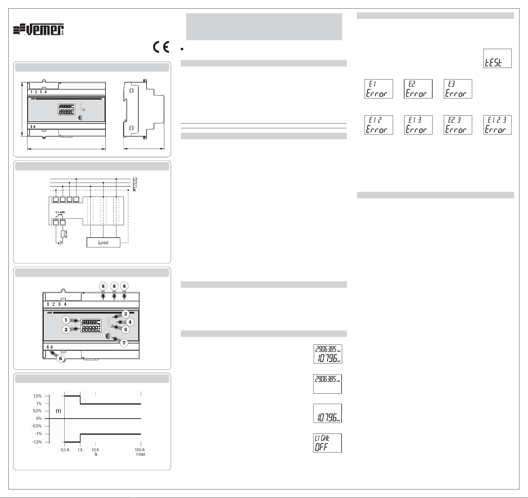
DEVICE DESCRIPTION
£®ÊÊ Ã«>ÞÊLÝÊvÊÌÌ>ÊiiÀ}Þ
Ó®ÊÊ Ã«>ÞÊLÝÊvÊ«>ÀÌ>ÊiiÀ}Þ
3) Green LED:ÊÜiÊÌÊÌÊ`V>ÌiÃÊ«ÜiÀÊÃÊ
4) Red LED:ÊiÛiÀÞÊv>ÃÊVÀÀië`ÃÊÌÊ>ÊiiÀ}ÞÊVÕÌÊvÊ£ä7
5) Yellow LED:ÊÜiÊÌÊÌÊ`V>ÌiÃÊÜÀ}ÊViVÌ
È®ÊÊ "«ÌÃÕ>Ìi`Ê«ÕÃiÊÕÌ«ÕÌ
Ç®ÊÊ *>}iÉL>V}ÌÊÃiiVÌÊiÞ
n®ÊÊ *iÀvÀ>ÌÃÊvÀÊ`ÀiVÌÊViVÌÊvÊÜÀiÃÊÌÊLiÊiÌiÀi`°
OPERATION
UÊÊ Ê7iÊÌiÊiiÀ}ÞÊiÌiÀÊÃÊÌÕÀi`ÊÊÌiÊ>Ê«>}iÊÃÊ`ë>Þi`]Ê
Ài«ÀiÃiÌ}ÊÌiÊÌÌ>ÊiiÀ}ÞÊVÕÌÊÊÌiÊÇ`}ÌÊÕ««iÀÊLVÊ>`ÊÌiÊ
«>ÀÌ>ÊiiÀ}ÞÊVÕÌÊÊÌiÊx`}ÌÊÜiÀÊLVÊ/iÊÀiÃÕÌÊvÊi>VÊ
iÌiÀÊÃÊ>ÕÌ>ÌV>ÞÊÕ«`>Ìi`Ê>ÃÊÃÊ>ÃÊÌiÊÃV>ii`ÊÃÊÀi>Vi`°
Ê ÊvÊÌiÊ9"7ÊÊÃÌ>ÞÃÊÊ>vÌiÀÊÌiÊ«iiÌÊÜ>ÃÊ«ÜiÀi`]ÊViVÊÌiÊ
installation for connection errors (cfr. “Connection errors”) section.
UÊÊ Ê/Ê`ë>ÞÊÌiÊtotalÊiiÀ}ÞÊÀi>`}ÊÞ]Ê«ÀiÃÃÊÌiÊ“Sel”ÊiÞ\ÊÌÃÊiÌiÀÊ
cannotÊLiÊÃiÌÊÌÊâiÀ
UÊÊ Ê/Ê`ë>ÞÊÌiÊpartialÊiiÀ}ÞÊÀi>`}]Ê«ÀiÃÃÊÌiÊ“Sel”ÊiÞÊ>}>\ÊÌÃÊ
iÌiÀÊÃÊâiÀi`Ê>ÕÌ>ÌV>ÞÊ>ÃÊÃÊ>ÃÊÌiÊi`ÊvÊÌiÊÃV>iÊÃÊÀi>Vi`Ê
°Ê7®ÆÊÌÊV>Ê>ÃÊLiÊÃiÌÊÌÊâiÀÊ>Õ>ÞÊ>ÞÌiÊLÞÊ`}ÊÌiÊ
“Sel”ÊiÞÊ«ÀiÃÃi`ÊvÀÊÀiÊÌ>Ê{ÊÃiV`Ã
UÊÊ Ê/ÊÀiÌÕÀÊÌÊÌiÊ>Ê«>}iÊÀi>`}ÊLÌÊiÌiÀÃÊÌÌ>Ê>`Ê«>ÀÌ>®]Ê«ÀiÃÃÊ
ÌiÊ“Sel”ÊiÞÊ>}>°
UÊÊ Ê>V}Ì}ÊÃÊi>Li`ÊLÞÊ`iv>ÕÌ\ÊÌÊÃÊÃÜÌVi`ÊÊi>VÊÌiÊ>ÊiÞÊÃÊ
«ÀiÃÃi`Ê>`ÊÃÌ>ÞÃÊÊvÀÊÎäÊÃiV`ÃÊ>vÌiÀÊÌiÊ>ÃÌÊiÞÊÜ>ÃÊ«ÀiÃÃi`°ÊÊ
À`iÀÊÌÊi>LiÉ`Ã>LiÊL>V}ÌÊÜiÊÊÌiÊmain page]Ê`Ê“Sel”
iÞÊ«ÀiÃÃi`ÊvÀÊ>ÌÊi>ÃÌÊ{ÊÃiV`Ã\Ê" É"ÊL>V}ÌÊÃÌ>ÌÕÃÊÜÊLiÊ
`ë>Þi`ÊvÀÊ>ÊVÕ«iÊvÊÃiV`Ã]Ê>vÌiÀÊÜVÊÌiÊ>Ê«>}iÊÜÊÀiÌÕÀ°
Mod. ENERGY-400 D90
Èx
ON
Sel
10Wh/imp
Energy-400 D90
10(90)A cl.1
3x230/400 V ~ 50/60Hz
!
£Óx°Ç
nÇ
1
4
5 6
2 3
L3
L2
L1
N
20 mA
0.1 kWh
Load
4-wire (3 phases plus neutral)
or 3-wire (without neutral)
ON
Sel
10Wh/imp
Energy-400 D90
10(90)A cl.1
3x230/400 V ~ 50/60Hz
!
(1) Indetermined error zone
Main page
Backlight status
Total reading
Partial reading
CONNECTION ERRORS
Ê ÊÕÀ}ÊÌiÊvÀÃÌÊÎÊÕÌiÃÊ>vÌiÀÊ«ÜiÀÕ«]Ê>ÊViVÌÊViVÕ«Ê
ÃÊ>ÕÌ>ÌV>ÞÊV>ÀÀi`ÊÕÌÊÌÊ`iÌiVÌÊ>ÞÊViVÌÊiÀÀÀÃ\ÊÌiÊ
«iiÌÊÜÊ}ÌÊÕ«ÊÌiÊ9"7ÊÊvÊÌiÊiiÀ}ÞÊ>ÌÊiÊÀÊ
ÀiÊ«>ÃiÃÊ>««i>ÀÃÊÌÊLiÊi}>ÌÛi°
Ê ÊÊÌÃÊV>Ãi]ÊvÀÊvÕÀÌiÀÊ`iÌ>ÃÊÊÌiÊ>VÌÕ>ÊiÀÀÀÊÌÞ«iÊ}ÊÌÊÌiÊ
totalÊiiÀ}ÞÊ«>}iÊ>`Ê`ÊÌiÊ“Sel”ÊiÞÊ`ÜÊvÀÊ}iÀÊÌ>Ê{Ê
ÃiV`Ã]ÊÕÌÊÌiÊ“tESt” reading appears.
Ê Ê7À}ÊViVÌÊÃÊ`V>Ìi`ÊLÞÊ>Êi}>ÌÛiÊiiÀ}ÞÊÀi>`}Ê£Ê
>`ÉÀÊÓÊ>`ÉÀÊήÊvÜi`ÊLÞÊÌiÊ“Error” message.
PHASE 1 error
E1 is negative
PHASE 2 error
E2 is negative
PHASE 3 error
E3 is negative
PHASE 1 and 2 error
E1 and E2 are negative
PHASE 1 and 3 error
E1 and E3 are negative
PHASE 2 and 3 error
E2 and E3 are negative
PHASE 1, 2 and 3 error
E1, E2 and E3 are
negative
Ê /iÊÌiÃÌÊV>ÊLiÊ«iÀvÀi`Ê>ÞÌiÊLÞÊëÞÊÀi«i>Ì}ÊÌiÊ>LÛiÊÃÌi«Ã°
Warning: to restore correct meter operation after an error reading has been
displayed, switch the meter off, check connection of phases (sequence of
phases R, S, T) and current; then power the meter up.
REFERENCE STANDARDS
vÀÌÞÊÌÊÕÀ«i>ÊÕÌÞÊ`ÀiVÌÛiÃ\
ÓääÈÉxÉÊÜÊ6Ì>}i®
2004/108/EC (E.M.C.)
ÃÊ`iV>Ài`Ê>VVÀ`}ÊÌÊÌiÊvÜ}ÊÃÌ>`>À`Ã\
■Safety: EN 61010-1
■Electromagnetic compatibility: EN 62052-11 and EN62053-21


