PowerCell PS-5 User manual

PS-5 Fuel Cell System
Instruction Manual

256
PS-5 User Manual
WARNING! FIRE OR EXPLOSION HAZARD
Failure to follow safety warnings exactly could result in serious injury, death or property
damage.
•Do not store or use gasoline or other flammable vapours and liquids in the vicinity of this or any
other appliance.
•Installation and service must be performed by a qualified installer, service agency or the gas
supplier.
IMPORTANT!
Carefully read all instructions in this manual before attempting to install, prepare, operate,
or service the equipment.
Follow the safety precautions and all warning statements given in the instructions.
Keep the manual for future reference.

356
PS-5 User Manual
Table of Contents
1Safety precautions ................................................................................................................ 4
1.1 Warning symbols ..................................................................................................................... 4
1.2 General safety.......................................................................................................................... 4
1.3 Stopping the PS-5..................................................................................................................... 6
1.4 Hydrogen gas safety................................................................................................................. 8
1.5 Electrical safety........................................................................................................................ 9
1.6 Disposal.................................................................................................................................... 9
1.7 Field Support............................................................................................................................ 9
2Introduction.........................................................................................................................10
2.1 Type selection guide .............................................................................................................. 10
2.2 Disclaimer............................................................................................................................... 10
2.3 About this manual.................................................................................................................. 10
2.4 Definitions and abbreviations................................................................................................ 11
3System description...............................................................................................................12
3.1 Overview................................................................................................................................ 12
3.2 Fuel cell module..................................................................................................................... 12
3.3 Cooling module...................................................................................................................... 14
3.4 Power and electronics module (PE)....................................................................................... 15
4Installation ..........................................................................................................................16
4.1 Tools and Materials................................................................................................................ 16
4.2 Pre-installation requirements................................................................................................ 16
4.3 Electrical connections ............................................................................................................ 21
4.4 Lifting instruction................................................................................................................... 21
4.5 Internal system connections.................................................................................................. 23
4.6 External system connections ................................................................................................. 24
4.7 Pre-Start Testing .................................................................................................................... 26
4.8 First Start................................................................................................................................ 26
4.9 Optional External Component ............................................................................................... 26
5Operation ............................................................................................................................27
5.1 Quick Guide............................................................................................................................ 27
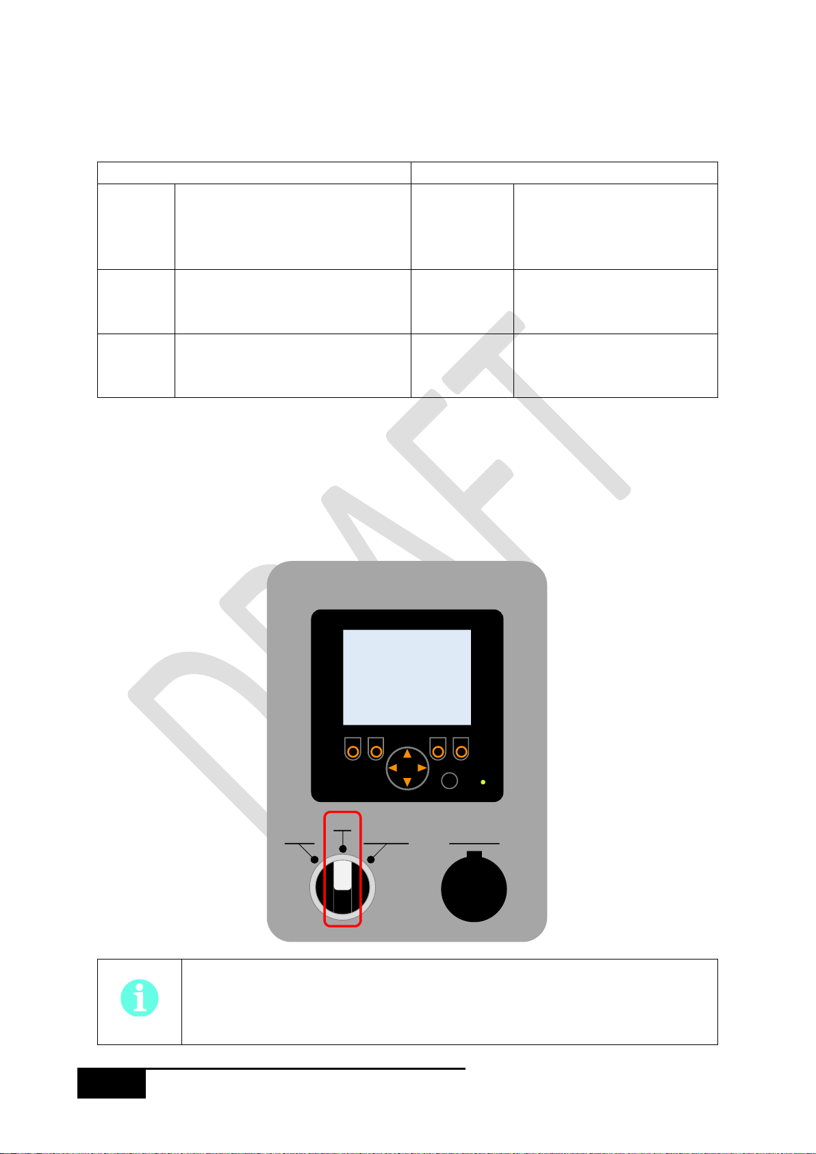
5.2 User interface......................................................................................................................... 29
5.3 Remote Control Mode ........................................................................................................... 33
6Troubleshooting...................................................................................................................34
6.1 Alarm Stop........................................................................................................................... 34
6.2 Alarm Shutdown ................................................................................................................. 36
6.3 Warnings................................................................................................................................ 38
7Service and Maintenance .....................................................................................................39
7.1 Service intervals..................................................................................................................... 39
7.2 Cleaning.................................................................................................................................. 39
7.3 Changing coolant ................................................................................................................... 40
7.4 Replacing the air filter............................................................................................................ 40
7.5 Replacing fuses ...................................................................................................................... 41
7.6 Hydrogen sensor replacement............................................................................................... 41
8Replacement and additional parts ........................................................................................42
8.1 Coolant................................................................................................................................... 42
8.2 Filter....................................................................................................................................... 42
8.3 Fuses ...................................................................................................................................... 42

456
PS-5 User Manual
8.4 Cabinet fan............................................................................................................................. 43
8.5 Hydrogen sensor.................................................................................................................... 43
Appendices .................................................................................................................................44
A Technical data........................................................................................................................ 44
B CAN configurations ................................................................................................................ 45
C Connection details ................................................................................................................. 51
D Menu system layout .............................................................................................................. 55
E Declaration of Conformity ..................................................................................................... 56
1 Safety precautions
The PS-5 has multiple layers of protection to reduce the risk and minimise the consequence of any
foreseeable hazard that the system will present. However, external factors to the PS-5, such as
improper use or a faulty installation, can present hazards that the PS-5 cannot control. Read this
manual carefully and follow all instructions and pay attention to the external requirements that the
end user must provide for the installation, found in Section 0. Any deviation from the instructions in
this manual will result in the cancellation of the system warranty.
1.1 Warning symbols
The following symbols are used in this manual:
WARNING
Potentially hazardous situation which could result in severe
personal injury, death, or severe damage to property, if the
instructions are not followed.
CAUTION
Potentially hazardous situation or unsafe practice that could
cause minor personal injury or damage to property, if the
instructions are not followed.
NOTE
Important additional information and recommendations.
1.2 General safety
The following list indicates the general safety points related to the PS-5. Keep in mind that the PS-5 is
a power generation system and should be treated with the same caution as any other electrical
generator system. The end user should think about who will have access to PS-5 and may want to
secure the area to prevent any unauthorised access to the system.
The area surrounding the PS-5 must be kept clear and free of combustible materials,
gasoline, and other flammable vapours and liquids. In addition, no ignition sources
should be present around the PS-5 system.

556
PS-5 User Manual
Do not block or obstruct the air openings on the PS-5, air openings communicating
with the area in which the PS-5 is installed, or the required spacing around the PS-5.
The air exhaust from the PS-5 is depleted due to part of the oxygen being consumed
in the electrochemical reaction in the PS-5. Unless the air exhaust is properly
ventilated, conditions around the PS-5 may become asphyxiating.
The PS-5 shall never be operated without its protective covers securely attached in
their correct places.
Do not use the PS-5 if any part has been under water. A flood-damaged fuel cell is
potentially dangerous. Attempts to use the PS-5 can result in fire or explosion. A
qualified service agency should be contacted to inspect the PS-5 and to replace all gas
controls, control system parts, electrical parts that have been wet.
When changing any of the serviceable parts of the PS-5, follow all instructions given
in this manual. Failure to do so may result in personal injury or death and may
irreversibly damage the PS-5.
The environmental conditions in which the PS-5 is installed must be pollution degree
2 or better (i.e. office environment) such that there is only non-conductive pollution
in the environment.
If any liquids spill from the PS-5, allow sufficient time for them to cool down before
cleaning them up as internal temperatures can reach 90°C and can present a burn
hazard.
The PS-5 uses an ethylene glycol based coolant which is moderately toxic when
consumed. Do not allow animals or children near coolant spills as ethylene glycol has
a sweet taste and so may taste like food.
Carefully examine the PS-5 installation and make sure that all intake and exhaust
openings are clear and free of obstructions, there are no cracks or gaps in rack that
the PS-5 is mounted in, and that there are no obvious signs of deterioration of
the PS-5.
The PS-5 must be located away from sources of refrigerant gasses or silicone vapors
as these can damage the fuel cell stack and gas sensing equipment.

656
PS-5 User Manual
1.3 Stopping the PS-5
The PS-5 has three OFF states and five ON states as described in the table below.
System OFF states
System ON states
OFF
All internal actuators are
unpowered and have their control
signal turned off. In this state, no
component can turn on.
ENABLED
The system is in an idle state
but it can automatically start
to generate power if the start
conditions are triggered.
IDLE
Internal components are powered
and may turn on through deliberate
user actions.
STARTUP,
DRYOUT,
SHUTDOWN
In these states, the system is
running but not generating
power.
FAILSAFE
A critical error has been detected
and has shut the system down. This
is equivalent to the OFF state.
RUN
In this state, the system is
running and outputting power
to the battery(s).
1.3.1 Immediate stop:
If a situation arises that requires the PS-5 to be immediately stopped, the switch on the front panel of
the device can be switched to the OFF position. This will switch the system to the OFF state and
immediately stop all internal components, close both fuel supply valves and disconnect the fuel cell
stack from the battery(s).
If the system is in the RUN, SHUTDOWN, or DRYOUT states when stopped, the normal
shutdown procedure will be skipped which can increase the degradation of the fuel
cell stack and decrease future performance.
Local
Off
Remote
Ethernet
ok

756
PS-5 User Manual
1.3.2 Normal stop:
The stop trigger depends on if the system has been started locally (s
) and the system configuration:
Local start:
Menu Auto-.
Remote start, hardware start configuration:
If the system is configured to have a remote hardware start trigger, the system is turned off by
disconnecting the hardware start signal through the means that the user has installed.
Remote start, CAN configuration:
If the system is configured to receive commands through CAN, the system is stopped by changing the
v (0).
If the system is in the ENABLED state, it will immediately switch to the IDLE state,
otherwise the system will run through, or finish, the normal shutdown procedure
before switching to the IDLE state.
BACK
>
>
>
SETTINGS
CONFIGURATION
FAILSAFE & SERVICES
SYSTEMSTATUS
MAIN MENU
>
BACK
W
W
Idle
0
5000
Output Power limit
Output Power
System State
Auto-start
SYSTEM STATUS
Disabled

856
PS-5 User Manual
1.4 Hydrogen gas safety
Hydrogen is a highly flammable gas that can release a vast amount of energy in a very short amount
of time. The main hazards of hydrogen are related to hydrogen leaks building up in contained areas
which can be effectively mitigated through simple precautionary actions. The first and foremost action
is to ensure that all pipes transporting hydrogen are leak tight and cannot be damaged in any
foreseeable event, the area around and above these pipes is properly ventilated, and that there are
no sources of ignition. Be aware that there may be local or national regulations on the storage and use
of hydrogen gas. It is recommended to install the PS-5 according to IEC standard 60079-10.
Hydrogen gas is highly flammable and when contained, it can be explosive. Avoid
ignition sources around and above the PS-5 to reduce the risk of fire or explosion in
case of a fuel leakage.
Hydrogen flames are invisible and emit little radiant heat so can be hard to detect. If
there is a suspected hydrogen fire, do not approach the PS-5, instead turn off the
supply of hydrogen and contact the local emergency service.
A large hydrogen leak in a contained area can deplete the atmosphere of oxygen and
so create an asphyxiation hazard. In the case of a large leak, do not approach the PS -5
or enter any small enclosed areas. Contact the local emergency service.
Hydrogen is incompatible with many materials. A common example is embrittlement
in metals, where the metal becomes fragile and can crack. Ensure that all pipe work
and tubing, including any seals, are compatible with hydrogen.
Hydrogen is very buoyant and rapidly disperses in an open environment. The major
hazards of a hydrogen leak can be mitigated by avoiding locations where hydrogen
can easily accumulate, such as an unventilated roof space, and ensure adequate
ventilation around the PS-5.

956
PS-5 User Manual
1.5 Electrical safety
The PS-5 can produce highvoltages and should not be used without its protective covers which prevent
direct contact with the internal electrical components. There may be local or national regulations
regarding the connections between the PS-5 and the battery bank(s) which require the wiring to be
carried out or certified by a registered electrician.
High voltages can be present inside the PS-5 or its output terminals. This voltage can
be sustained even after the hydrogen fuel supply is stopped. Make sure the PS-5 has
no electrical potential between the power terminals before any work is carried out.
Do not perform any service activities on the PS-5 while it is connected to the batteries.
Always disconnect the batteries before starting to service the system.
The fuel cell stack can sustain a high voltage for several hours after the fuel supply has
been stopped. Do not attempt to access the fuel cell stack or the electronics circuit
boards at the rear of the PS 5 as these can remain energized.
1.6 Disposal
The PS-5 should be disposed of at an authorised disposal centre. Apart from the coolant which is
discussed below, there are no components that require specific treatment for disposal; however, there
may be local or national regulations on the disposal of the fuel cell stack itself.
The PS-5 coolant is ethylene-glycol based and is treated as anti-freeze which typically must be disposed
of at an authorised hazardous material recycling centre.
1.7 Field Support
To request field support for items not included in the User Manual, please contact PowerCell or refer
to your service agreement:
PowerCell Sweden AB
Ruskvädersgatan 12
SE-418 34
Göteborg
Sweden
+46 (0)31-720 36 20

10 56
PS-5 User Manual
2 Introduction
The main application for the PS-5 system is for it to be a float voltage or controlled power battery
charger that can monitor one or two battery banks. The PS-5 will continuously monitor the battery
voltage and when it detects a low voltage it will automatically start up and charge the battery to a set
voltage and then turn itself off. When configured to output to two battery banks, the PS-5 will treat
each output independent of the other so it can charge a single battery bank or both at the same time,
and the batteries can be held at different voltages.
The PS--5 can be setup with
a radiator to reject waste heat to the environment, or a heat exchanger which can recover the heat
and use it for heating at the installation location.
2.1 Type selection guide
PS5 - - - - - -
Maximum power (kW) Internal Hydrogen Sensor
1.6, 3.3, 5 1 = Installed, 0 = Not installed
Battery voltage (VDC) Cooling Option
24, 48 HEX = Heat exchanger, RAD = Radiator
Fan mounting direction
U = Upwards, B = Backwards
*PS5 5 24 variants are not available.
*PS5 5 RAD variants have a limitation on the ambient temperature.
2.2 Disclaimer
PowerCell takes no responsibility for any damage or injury caused by improper use of the PS-5 or from
user actions that are not expressly stated in this manual.
2.3 About this manual
This manual contains all information required to install, operate, and maintain the PS-5 system. No
special qualifications are required to operate or maintain the PS-5, but there may be local and/or
national regulations on its installation such as requiring the electrical connections to be performed by
a qualified electrician. It is the responsibility of the end user to comply with all applicable regulations
regarding, but not limited to, the installation, operation, and disposal of the PS-5.

11 56
PS-5 User Manual
2.4 Definitions and abbreviations
BOP
Balance of Plant: all process components other than the fuel cell stack.
CAN
Controller Area Network: a digital communication protocol that the PS-5 uses for
internal and external communication.
CVM
Cell Voltage Monitor: the device that measures all individual cell voltages in the
fuel cell stack and is used to monitor the health of the fuel cell stack.
FCM
Fuel Cell Module: the PS-5 module that contains the fuel cell stack and most
process components.
HMI
Human-Machine Interface: The screen that the user can set and view various
system parameters.
kWe
kilo-Watt Electrical: the electrical power output of the PS-5.
LPM
Liters Per Minute: a unit of liquid flow.
PCB
Printed Circuit Board: a custom electronics board that handles various tasks.
PE
Power Electronics: the PS-5 module that contains the DC/DC converters that
stabilize the output voltage and provide stabilized 24VDC power to the fuel cell
module.
PLC
Programmable Logic Controller: the internal controller that handles all control
logic of the PS-5 and various other tasks such as data logging.
RTC
Real Time Clock: an internal clock that keeps the time even if the PS-5 is not
powered.
SLPM
Standard Litres Per Minute: a gas flow rate under standard ambient conditions
(101325 Pa and 298.15 K).

12 56
PS-5 User Manual
3 System description
3.1 Overview
The PS-5 consists of three modules: the fuel cell module, the cooling module, and the power
electronics module. Note that the fuel cell and cooling modules are physically connected and cannot
be separated. Each module has a ventilation inlet on the front and outlet on the back/top which allow
air to pass through. The fuel cell module has a user interface screen where the state and operational
variables of the PS-5 can be viewed and battery parameters can be set. There is also a switch that can
set the system to be in an OFF or ON state and an Ethernet connection which is used for system
servicing. All electrical and process connections are located on the back of the modules and these are
detailed in the individual module sections below. Each individual module has a label located on the
rear side which details the specifications of the module.
3.2 Fuel cell module
The fuel cell module houses the fuel cell stack and all the main process components; including the air
and recirculation compressors, the humidifier, the coolant pump and tank, and the system controller.
There are three options available for the stack size, which corresponds to an output power of 1.6, 3.3,
or 5.0 kWe, and there are two options available for the position of the ventilation fan. For a more
detailed description of the connections see Appendix C, and for a layout of the user interface screen
see Appendix D.
Fuel Cell
Module
Cooling Module
(typeHEX)
Power Electronics
Module
User Interface
Screen and
on/off switch.

13 56
PS-5 User Manual
1
11
Hydrogen outlet (purge)
2
Off / Local / Remote switch
12
Hydrogen inlet
3
Fuse box (behind grating)
13
Grounding contact point
4
Process air inlet (behind grating)
14
FCM BOP power supply
5
Ethernet port
15
Equipment CAN bus
6
User interface screen
16
External CAN bus
7
PE module signals connection
17
System status/control signals
8
Cabinet equipment connection
18
External tank valve control
9
Stack electrical output (x2)
19
10
Process air outlet
The hydrogen consumption of the FCM is dependent on the power output and the degradation of the
fuel cell stack, where an increase in either increases the fuel consumption. The table below shows the
hydrogen consumption at the start of the system lifetime, but as the PS-5 approaches its end-of-life
the consumption increases by up to 60%.
HYDROGEN CONSUMPTION
SLPM
GRAMS PER MINUTE
PS5 - 1.6 - - - -
23
1.9
PS5 - 3.3 - - - -
43
3.6
PS5 - 5.0 - - - -
65
5.4
Front View
Back View

14 56
PS-5 User Manual
3.3 Cooling module
The cooling module removes the heat generated by the fuel cell stack and transfers it to an external
water supply, such as a house heating system, or rejects it to the environment. This module is directly
attached to the FCM and there are internal connections between the two modules so they cannot be
separated after delivery. The cooling module contains a drain behind the front panel which can be
used to drain the coolant and it also contains a spill catch plate that will collect any internal liquid spills
and direct them to a drain point at the back of the module. The two variants of the cooling module are
shown separately below.
3.3.1 HEX type cooling module
The HEX type cooling module contains a heat exchanger and there are two connections on the back of
the module for the supply and return of the external cooling media. Refer to Section 4.2 for information
on the minimum flow rate require to provide enough cooling for the PS-5.
1
FCM ventilation air inlet
3
External cooling water supply
2
External cooling water return
4
Internal spill drain point
3.3.2 RAD type Cooling module
The RAD type cooling module contains a radiator and fan to reject heat to the environment. There are
no external connections on this module but refer to Section 4.2 for the minimum ambient
requirements needed to provide the required flow rate of air to the radiator.
1
FCM ventilation air inlet
3
Internal spill drain point
2
Radiator air inlet
4
Radiator air outlet
Front View
Back View
Back View
Front View

15 56
PS-5 User Manual
3.4 Power and electronics module (PE)
The power electronics module contains two DC/DC converters which take the fuel cell stack voltage
and either reduce or increase it to match the battery voltage. This module also contains two more
DC/DC converters which output a stabilised 24 VDC that many of the internal PS-5 components require
to run. This module has two variants as to whether it is outputting to 24 VDC or 48 VDC batteries. For
a detailed description of the connections see Appendix C.
1
Ventilation Fans (x2)
6
Electrical output to battery (#2)
2
Ventilation air output (x2)
7
Grounding contact point
3
Electrical input from FCM (#1)
8
FCM signal connections
4
Electrical output to battery (#1)
9
BOP power supply (to FCM)
5
Electrical input from FCM (#2)
The number of batteries must match the software configuration, one or two outputs,
otherwise the batteries may become damaged through over- or under-charging.
If the power electronics module is located below the cooling module, take care that
no liquid can be spilled onto the electrical connections on the rear of this module.
If the PS-5 is connected to two separate batteries, it may be unable to output its full
capacity to a single battery.
Back View
Front View

16 56
PS-5 User Manual
4 Installation
Before installing the PS-5, read all the installation instructions and make sure that the installation
location meets all requirements set out in this section. The PS-5 should be fully installed before it is
electrically connected to the batteries as this will power the system. Other installation requirements
may come from local or national regulations and it is up to the end user to abide by requirements set
by these.
4.1 Tools and Materials
The base installation case requires a 3mm HEX key to attach the PS-5
flat-head screwdriver to secure electrical cable connections. In addition to this, the PS-5 needs to be
electrically grounded using the attachment points on the back of each module. If the installation case
has additional external equipment, then further tools and materials may be needed on a case-by-case
basis.
4.2 Pre-installation requirements
The first and foremost pre-
PS-5 to be installed within. The installation of the PS-5 requires access to the back of the system to
connect wires and pipes so there needs to be enough room to access the rear connections when it is
installed in the rack; the rear section of the PS-5
be restricted. It is recommended to install the PS-5 within a 42U as this provides enough height for the
entire system. It is also recommended to have a sliding shelf that the PS-5 can be placed on to help
support the weight of the system and to aid installation and any maintenance activities. If the PS-5 is
installed with the HEX cooling module, it is recommended that this shelf is installed 65 cm off the
ground; and with the RAD module, it is recommended to be 40 cm off the ground. This will place the
HMI approximately 150 cm off the ground which it a comfortable height to use it. The PS-5 must be
mounted vertically and up the right way in the rack.
The rack that the PS-5 is installed in must be securely mounted to the floor to prevent
the entire system falling over.
4.2.1 Location and Environment
The PS-5 must be installed in an indoor location that is classified as Pollution Degree 2 or better. This
means that there should be no conductive pollution in the environment and that only temporary
conductivity from condensation can be expected; examples of this type of environment include
residential and commercial building, laboratories and test stations. Other types of equipment that
typically require Pollution Degree 2 include household appliances, audio and visual equipment, test
and measurement equipment, and industrial control products.
The site that the PS-5 is installed in must not be routinely occupied by personal, or directly attached to
a building or area that is routinely occupied. In addition, the PS-5 must be located at minimum two
meters away from non-fire protected walls or ceilings. Other installations are possible but the user
accepts all additional risks associated with the non-standard installation site. The user must perform a
risk analysis with respect to, but not limited to, the following parameters: occupancy, flammability of

17 56
PS-5 User Manual
surrounding materials, and external safety system, and determine if the installation case meets an
adequate level of safety.
There must be adequate space around the PS-5 to allow sufficient ventilation of the system and access
to the front of the PS-5 where the user interface screen and the on/off switch are located, and where
maintenance is carried out from. If the PS-5 is installed inside a cabinet, there should be a minimum
clearance of 10 cm at the front and 10 cm at the rear of the fuel cell module to allow ventilation air to
pass through the system. If the RAD type cooling module is installed, the user must ensure that there
is enough space to allow the required air flow to pass through the cooling module. For maintenance
purposes, it is recommended to have an area that is at minimum a 1x1 meter area at the front of the
PS-5.
4.2.2 Ventilation
System Ventilation:
The PS-5 requires a minimum fresh air supply of 350 m3/h to cover the fuel cell stack air requirements
(1-31 m3/h), the ventilation of the fuel cell module (~300 m3/h), and the ventilation of the power
electronics module (~60 m3/h). This air must meet the requirements set out in Section 4.2.1. The
ventilation air can remove up to one kilowatt of heat from the PS-5, depending on the electrical load,
which needs to be considered in the ventilation sizing of the room or building containing the PS-5.
Radiator Ventilation (RAD type cooling module only):
In addition to the minimum system ventilation described above, if the PS-5 is equipped with a RAD
type cooling module, additional ventilation air is required to remove all remaining heat generated by
the fuel cell stack; the heat generation is shown graphically is Section 4.2.4. This additional air
requirement highly depends on the ambient air temperature, where a typical indoor temperature of
20°C requires 400-700 m3/h of fresh air, while high ambient temperatures of 35°C require up to
1000 m3/h of fresh air. If a ventilation system is installed around the PS-5, this must have a pressure
drop of no more than 50 mbar at 1000 m3/h and must be designed to handle air temperatures of up
to 70°C.
Purge Ventilation:
As the anode (hydrogen) side of the fuel cell stack is a closed circuit, any contaminants in the feed
hydrogen slowly accumulate and will eventually starve the fuel cells of hydrogen. To prevent this from
occurring, a portion of hydrogen is purged from the anode which also removes some of this
contamination; the purge frequency depends on the system load. This purge gas can contain up to
100% hydrogen and so must be treated as flammable, although only a small volume is purged in any
given purge cycle. A recommended method of handling this purge gas is to combine it with the process
air outlet which will, but is not guaranteed to under all situations, dilute the hydrogen to a
non-flammable concentration.
The PS-5 has been designed and tested with a vertical hydrogen purge vent line, which is a venting
system that is not affected by wind or rain; an example of such a setup is shown in the figure below
where a vent line is raised above the roof of the room containing the PS-5. A water separation and

18 56
PS-5 User Manual
collection vessel is required on the hydrogen purge line to collect and drain water to a predefined
location; the water drain system must not allow vent gas to escape through the drain line.
Two examples of a vertical process venting setup
The user can install a vent system themselves that complies with the following statements (adapted
from EN 62282-3-100 section 4.5.3). The vent system must:
•contain no asbestos or other hazardous materials (lead, mercury, etc.).
•be made from stainless steel or other compatible material.
•be designed to minimize abrasion, corrosion, and not disassemble or become damaged during
use.
•be compatible with temperatures ranging from 2°C to 80°C.
•be properly supported and have a rain cap that does not limit exhaust flow.
•be leak tight.
•have a liquid drain to prevent liquid water from accumulating.
The vent system must discharge the hydrogen to the environment in a location where it cannot
accumulate. The area around the vent line that should be kept clear should be dimensioned at a site-
by-site basis, based on local and/or national regulations (e.g. IEC 60790-10). Finally, the vent system
must not excessively restrict the flow from the PS-5; the total pressure drop of each vent line must be
less than 50 mbar. Keep in mind that a higher backpressure causes the compressors to require more
power and results in a lower overall system efficiency.
4.2.3 Fuel
The feed hydrogen to the PS-5 must be of grade 3.5 or higher (99.95% hydrogen) to limit the exposure
of contaminants to the fuel cells and it must be supplied at a pressure in the range 3-6 bar(g). To comply
with fuel cell system safety regulations (EN62282-3-100), a second feed valve must be installed on the
hydrogen feed line and ideally this is located as close to the source of hydrogen as possible. This valve
must be a normally-closed (NC) type valve and be connected to the PS-5 using the connections labeled
The recommended setup should include an upstream pressure
FCM
Module
Air Out -
H2Purge -
Water Drain Valve
Water Collection
Vent Line
(with weather cap)
FCM
Module
Air Out -
H2Purge -
Seperate anode
and cathode vent
lines
Joint anodeand
cathode vent line

19 56
PS-5 User Manual
regulator to supply hydrogen at the required 3-6 bar(g), a pressure relief valve as an overpressure
protection, and the required tank valve that is connected to the FCM; a schematic of this is shown
below.
An example of the hydrogen supply system
A high inlet hydrogen pressure can damage the inlet equipment and in an extreme
case, it can rupture the seals on the feed valve and cause a major hydrogen leak.
Over-pressure protection should be installed on the feed hydrogen line to prevent this
from occurring.
If there is a potential for a static charge to be built up in the hydrogen supply piping,
the piping should be grounded to prevent this from occurring.
The PS-5 has no means to measure the feed hydrogen pressure so an external sensor
or gauge is required to correctly set the feed pressure.
4.2.4 Coolant
The internal coolant is circulated through the fuel cell stack and comes into direct contact with each of
the fuel cells to efficiently remove excess heat from the reaction. Because of this, the coolant has strict
requirements on its electrical conductivity to prevent a short circuit inside the fuel cell stack and
normal coolants are unable to meet these requirements. The preferred coolant is Dynalene FC-EG
which is an ethylene glycol based coolant and has additives which actively removes free ions from the
coolant and keeps the electrical conductivity low. This coolant should be replaced at every two years
or 1000 run hours, whichever is shorter, to ensure that the ion absorption remains high. Contact
PowerCell to purchase new Dynalene FC-EG.
Do not put any water in the internal coolant tank. This will dilute the coolant and cause
the electrical conductivity to rise and eventually it will lead to a short circuit inside the
fuel cell stack and will cause permanent damage.
FCM Module
- H2Inlet
- Tank Valve
H2Supply
Pressure
Regulator
Relief
Valve
Tank
Valve
(NC)
H2(200 bar)
H2(200 bar)
(3-6 bar)

20 56
PS-5 User Manual
External Coolant (HEX type cooling module only):
The external coolant passes through a heat exchanger which transfers heat from the internal coolant
loop and so is physically separate from the internal loop. The external coolant can be any liquid that is
compatible with stainless steel and copper, which covers all typical cooling/heating fluids. The external
coolant has a maximum inlet pressure of 2.5 barg, and a maximum flow rate of 45 LPM; these
conditions allow the PS-5 to be integrated into a wide range of heat recovery systems. The minimum
coolant flow-temperature requirements at maximum electrical output are shown below, where the
coolant must be below the curve and in the operating zone. Note that the operating zone is extended
for the 3.3 kWe and 1.6 kWe versions of the PS-5 as they do not generate as much heat as the 5.0 kWe
version.
The external coolant minimum flow/temperature combination and the coolant operating zone
The external coolant must not have any dirt or particles in it otherwise the heat
exchanger may become partially or fully blocked. This can reduce the cooling capacity
and the PS-5 will then limit its power output to prevent overheating.
The amount of heat generated by the fuel cell stack is dependent on how much electricity is being
generated, where more electricity results in more heat. In addition, as the stack ages, the cell efficiency
drops and more heat is generated for a given electricity output. The following graph shows the range
of heat generation as a function of electrical generation for each of the different sized PS-5 systems;
at the beginning of the system lifetime the operating curve will be at the bottom of this range, and as
the system ages it will approach the upper curve.
0 5 10 15 20 25 30
0
10
20
30
40
50
60
70
Coolant Inlet Temperature / C
Coolant Flow Rate / LPM
PS5 - 5.0 -
PS5 - 3.3 -
PS5 - 1.6 -
Operating Zone
Table of contents
Popular Power Supply manuals by other brands

Elenco Electronics
Elenco Electronics XP-605 instruction manual

American Magnetics
American Magnetics 601 Installation, operation and maintenance instructions

R&S
R&S NGM202 user manual

Altronix
Altronix ALTV248ULHi installation guide

Portable Power Systems
Portable Power Systems PPS-500 user manual

LEGRAND
LEGRAND KEOR MOD installation manual