Victory Primary Case Kit Installation
PKT-065
Introduction: Made in USA
This easy to install, high quality, Powerlet™ kit provides a convenient way to
access the battery on Victory otorcycles. The operator can supply power to
the battery (i.e. battery charger), draw power fro the battery (i.e. heated
vest), or onitor the state of charge on the battery using the Powerlet socket.
Please read all of the instructions carefully before attempting the
installation of this product Have this kit installed by a trained
technician if you are not familiar with these procedures
Quick Start Instructions:
STEP #1 Re ove left side panel to expose the battery.
STEP #2 Connect the socket and install the fuse.
STEP #3 Route the wires.
STEP #4 Mount the bracket.
STEP #5 Attach the tie-wrap & inspect.
STEP #6 Test & reasse ble.
Detailed Instructions:
STEP #1 – Re ove left side panel to expose the battery. See the service
anual.
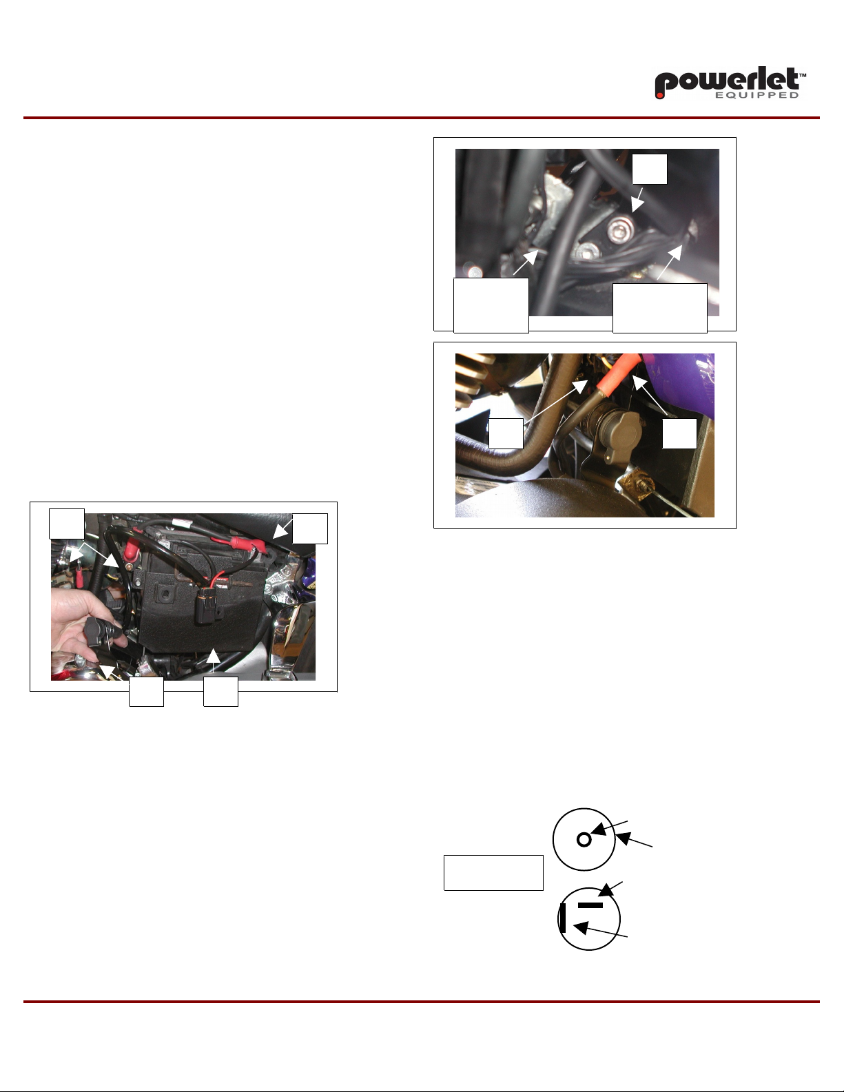
STEP #2 – Attach the white connector to the back of the Powerlet socket and
slip on the black boot [A]. Install the fuse in the fuse-holder [B].
STEP #3 – Next re ove the negative battery connection, followed by the
positive battery connection. Slip the red wire under the red battery boot [C].
You ay need to tri the red boot to acco odate the added wire. Connect
the red & black wire as follows:
RED WIRE = BATTERY POSITIVE
BLACK WIRE = CHASSIS GROUND
Tie-wrap the cap of the fuse holder to the large positive wire on top of the
battery.
STEP #4 – Re ove the top clutch cable ounting bracket bolt [E]. Loosen
the ground lug [F] & re ove the lower solenoid cable [D] to ease the
installation. Slip the notch in the bracket over the lower clutch cable bracket
bolt and align the bracket with the top hole. Add the supplied washer to the
clutch bracket top bolt [E] & tighten the ground and clutch bracket bolts.
Reinstall the solenoid cable [D].
STEP #5 – Apply the second tie-wrap to the harness on the left side of
the battery box where it crosses the main ground wire [G] This will
keep the wire from touching the exhaust Do NOT allow the harness to
directly contact the motor or exhaust
STEP #6 – Use a volt eter to check if the polarity is correct. The center
ter inal of the Powerlet socket is plus and the outer ring is negative (see dwg
below). Replace the side cover. Enjoy!
Copyright 2006-2009 Powerlet LLC PATENTS PENDING Septe ber 14, 2009
PHONE: 586-932-6886 WEB SITE: www.powerlet.net
POSITIVE
NEGATIVE
POWERLET
NEGATIVE
FRONT
REAR
POSITIVE
CLUTCH
CABLE
BRACKET
[F]


