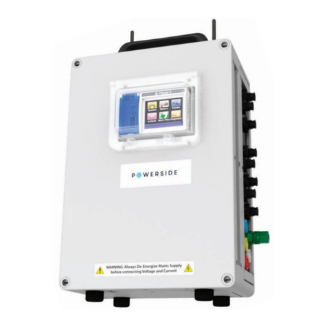
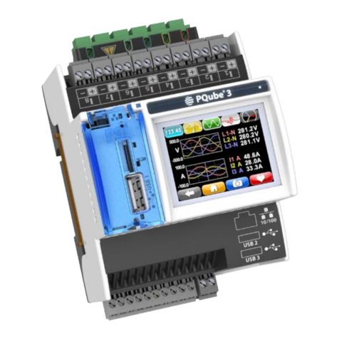
POWERSIDE PQube 3 User manual

Powerside 980 Atlantic Ave. Suite 100
Alameda, CA 94501, USA
Tel +1-510-522-4400 │Powerside.com
PQube® 3 Power Analyzers
Operation and Reference Manual
Revision 3.4

Page 2 of 49
Manual#: 851-000134
Version 3.4 –08/11/2022
If this equipment is used in a manner not specified by the manufacturer, the protection provided by
the equipment may be impaired. Installation, service, and maintenance of your PQube 3 must only
be done by qualified personnel for electrical installations.
The information contained in this document is subject to change without notice.
POWERSIDE MAKES NO WARRANTY OF ANY KIND WITH REGARD TO THIS MATERIAL, INCLUDING,
BUT NOT LIMITED TO, THE IMPLIED WARRANTIES OF MERCHANTABILITY AND FITNESS FOR A
PARTICULAR USE.
Powerside shall not be liable for errors contained herein or for incidental or consequential damages
in connection with the furnishing, performance, or use of this material. If you do not accept this
limitation on liability, please return the product to Powerside prior to use.
Produced in the United States of America.
Symbol
Meaning
Caution. Consult this manual in all cases where this
symbol is marked, in order to find out the nature of
the potential hazards and any actions which have
to be taken to avoid them.
Caution. Risk of electric shock.
Alternating current.
Alternating current (AC) or direct current (DC).
Double or Reinforced insulation.
Functional earth terminal not relied on for safety.
© 2008–2022 Powerside. All rights reserved. No parts of this document may be copied, reproduced, or translated to another language
without the prior writtenconsent of Powerside. “PQube 3” is a registered trademark of Powerside. “Windows” “Excel,” and “PowerPoint” are
registered trademarks of Microsoft Corporation. All product names, trademarks and registered trademarks are property of their respective
owners.
WARNING: Death, serious injury, or fire hazard could result from improper connection or
operation of this instrument. Carefully read and understand manual before connecting this
instrument.
AVERTISSEMENT: Si l'instrument est mal connecté, la mort, des blessures graves, ou un
danger d'incendie peuvent s'en suivre. Lisez attentivement le manuel avant de connecter
l'instrument.
WARNUNG: Der falsche Anschluß dieses Gerätes kann Tod, schwere Verletzungen oder Feuer
verursachen. Bevor Sie dieses Instrument anschließen, müssen Sie die Anleitung lesen und
verstanden haben.
ADVERTENCIA: Una conexión incorrecta de este instrumento puede producir la muerte,
lesiones graves y riesgo de incendio. Lea y entienda el manual antes de conectar.

Page 3 of 49
Manual#: 851-000134
Version 3.4 –08/11/2022
Contents
1Introduction 5
2PQube 3 Operation 6
2.1 User Controls .................................................................................................................... 6
2.1.1 Navigating the Touchscreen Display 6
2.2 Rebooting the PQube 3................................................................................................... 14
2.2.1 To perform a software reboot 14
2.2.2 To perform a hardware reboot 15
2.2.3 Ejecting your USB thumb drive or microSD card 15
2.3 Accessing the FTP Server on Your PQube 3..................................................................... 16
2.4 Accessing the HTTP Web Server on the PQube 3............................................................ 17
2.4.1 Meters 18
2.4.2 Events 19
2.4.3 Trends 20
2.4.4 Commands 21
2.5 PQube 3 Email Setup ...................................................................................................... 22
2.5.1 Setting Up an Email Account on the PQube 3 22
2.5.2 Getting event notifications and trend data from the PQube 3 by email 24
2.5.3 Sending commands to the PQube 3 over email 25
2.6 Modbus Setup................................................................................................................. 26
2.6.1 Scan Rates, Client Load, and Limitations 26
2.6.2 Supported Clients 26
2.6.3 Register List (refer to Modbus Reference Manual) 26
2.6.4 Downloads 26
3Upgrading the Firmware on your PQube 3 27
3.1 Apply Firmware Updates Locally .................................................................................... 27
3.2 Apply Firmware Updates Over the Web......................................................................... 27
3.3 Apply Firmware Update over Network........................................................................... 28
4Maintenance 29
4.1 Turning Off Your PQube 3............................................................................................... 29
4.2 Replacing Your PQube 3’s Clock Battery......................................................................... 29
4.3 Life Expectancy of the PQube 3 and the PM1 module.................................................... 29

Page 4 of 49
Manual#: 851-000134
Version 3.4 –08/11/2022
4.4 UPS1 Life Expectancy and Long-Term Storage Instructions ............................................ 29
4.5 Cleaning Instructions ...................................................................................................... 30
4.6 Reasons for Reset ........................................................................................................... 30
4.7 Calibration Information for Your PQube 3...................................................................... 30
5Reference 31
5.1 List of Recorded Parameters........................................................................................... 31
5.1.1 List of recorded voltage parameters 31
5.1.2 List of recorded conducted emission parameters 31
5.1.3 List of recorded current parameters 32
5.1.4 List of recorded environmental parameters 32
5.1.5 List of recorded analog channel parameters 33
5.2 PQube 3 Operating Modes ............................................................................................. 34
5.2.1 PQube 3 LED Blinking Modes 34
5.2.2 GPS-R —LED Indications 35
5.2.3 PM1/PM2 —LED Indications 35
5.2.4 UPS1/2/3 —LED Indications 36
5.2.5 ENV2 —LED Indications 36
5.3 List of Email Commands.................................................................................................. 37
5.4 List of Email Error Codes ................................................................................................. 38
5.5 List of Error Messages..................................................................................................... 39
5.6 MS1 Module to GPS1 Receiver 8-pin Cable Pinouts:....................................................... 40
5.7 PQube3 Event Types....................................................................................................... 41
5.7.1 Triggering mechanism - general overview 42
5.7.2 Event Parameters 44
5.8 Major Sag (Dip) Curves ................................................................................................... 46
5.8.1 STANDARD 46
5.8.2 SEMI F47 47
5.8.3 Samsung Power Vaccine 47
5.8.4 ITIC 48
5.8.5 CBEMA 48
5.8.6 MIL STD 704E 49
5.8.7 MIL STD 1399 49

Page 5 of 49
Manual#: 851-000134
Version 3.4 –08/11/2022
1Introduction
Pleasenote that for most users,the PQube 3 Installation Manual covers allthe necessaryinformation
for installing the PQube 3 modules, CTs, wiring, and configuring. The PQube 3 is easy to use with an
intuitive interface and is shipped preconfigured to cover the majority of use cases.
If more information is required, this Operation and Reference Manual addresses user controls,
setting up emails, upgrading firmware, maintenance, operating modes, specifications, and other
detailed references for the PQube 3 family. It also contains detailed error codes and commands for
email as well as a list of industry-standard sag curve specifications for reference.

Page 6 of 49
Manual#: 851-000134
Version 3.4 –08/11/2022
2PQube 3 Operation
2.1 User Controls
2.1.1 Navigating the Touchscreen Display
Use the touchscreen on your PQube 3 to navigate the display. You can view live meters, recent
events, system information, and perform actions like ejecting removable media and rebooting the
unit.
Use the Back button to
go back one screen.
Use the Home button
(2nd to left) to go
directly to the main
screen.
You can save
screenshots if you
have a USB drive
plugged in.

Page 7 of 49
Manual#: 851-000134
Version 3.4 –08/11/2022
System
Date/time: You can change the time and day manually unless you are configured
to synchronize on SNTP or NTP, or your PQube 3 is connected to GPS.
Your PQube 3 will automatically set the correct date and time upon configuring
the Setup.ini files or connecting to a network.
If SNTP or NTP has been enabled in the Setup.ini file, the PQube 3 will
synchronize to UTC time. All measurements will be time tagged with the local
time zone.
Power configuration: This screen shows you the power configuration, nominal
voltage, and nominal frequency that your PQube 3 is using.
Information: Look up your PQube 3’s firmware version, serial number.
Language: Select the language for the user interface on your screen. By default,
the language is English-US.
Network: Your PQube 3’s IP address and MAC address can be found on this
screen. This is useful if you have a dynamic IP address. It is also useful for
troubleshooting connectivity issues. An external network cable must be plugged
in.

Page 8 of 49
Manual#: 851-000134
Version 3.4 –08/11/2022
Advanced: UPS battery status, GPS synchronization status, and IOT Token
number are available here.
Meters
Voltage and Frequency: These are line-to-line, line-to-neutral, and neutral-to-
earth true-RMS voltmeters. Different meters will show on these screens,
depending on your power configuration. (For example, if the power configuration
is “delta,” there will not be any L-N meters, because there is no neutral
conductor.) If you have set a potential transformer ratio in your Setup.ini file, the
values will reflect this ratio.
Current: These meters show the true-RMS current. If you have set a current
transformer ratio in your Setup.ini file, then these meters will use that ratio, so
these meters will sometimes show their values in kilo-amps or even mega-amps.
Different meters will show on this screen, depending on your power
configuration. (For example, if the power configuration is “delta,” this screen will
not show a neutral current meter, because there is no neutral conductor in delta
power.)
Note: The PQube 3v measures voltage only and will not show any readings for
current or power.

Page 9 of 49
Manual#: 851-000134
Version 3.4 –08/11/2022
Power: These are the true power, apparent power, and reactive power readings,
and they correctly handle harmonics (distorted voltages and distorted currents). If
you have set a current transformer ratio or potential transformer ratio in your
Setup.ini file, then these meters will reflect those ratios.
Peaks: These meters show the peak values on Load, Watts and VARS reached.
The Peak accumulators can be reset by pressing the Reset button .

Page 10 of 49
Manual#: 851-000134
Version 3.4 –08/11/2022
Energy: These three meters show the total energy, apparent energy, and reactive
energy. The energy accumulators can be reset by pressing the reset button
.
Class A: You will find additional power quality parameters as defined in IEC
61000-4-30 Class A, the international standard for power quality measurement
methods.
Flicker: These meters show flicker according to IEC 61000-4-15 Edition 2
methods. Pinst is the instantaneous flicker value for Incandescent Flicker. Pst is the
short-term flicker, a statistical analysis of Pinst after 10 minutes, synchronized to
real-time clock. Plt is the mean value of Pinst over previous 2 hours, synchronized
to real-time clock.
Unbalance: These meters show the voltage unbalance and the current
unbalance. You can choose whether your PQube 3 calculates unbalance using the
ANSI C84.1 method, IEC method, or GB method in your Setup.ini file.
Harmonics: Use this screen to view every harmonic up to the 50th for both voltage
and current. Select one harmonic at a time. The selected harmonic applies to all
channels. (Harmonic values up to the 50th are recorded in your PQube 3’s CSV
files.)

Page 11 of 49
Manual#: 851-000134
Version 3.4 –08/11/2022
Interharmonics: Use this screen to view every Interharmonic up to the 50th for
both voltage and current. Select one harmonic at a time. The selected
Interharmonic applies to all channels. (Harmonic values up to the 50th are
recorded in your PQube 3’s CSV files.)
2 to150 kHz: Use this screen to view the conducted emissions in the 2 to150 kHz
range. Useful for monitoring noise due to interference sources including solar
inverters.
More meters: Additional meters can be found here.
Analog Channels: The Analog meters show the RMS voltage (equivalent to DC
voltage for DC signals). You can view the Analog-to-Earth channels (common
mode) and the Analog-to-Analog channels (differential mode).
The internal pull-up voltage is 2.5 Vdc floating. It will zero out once you connect
something to these terminals.
Environmental Meters: If you have ENV2 environmental probes, you can view
your temperature, humidity, barometric pressure, acceleration, thermocouple
input, and solar irradiance input here.
Digital Input: The DIG1 meter shows the average value of the DIG1 digital input
averaged over one cycle—useful when the DIG1 signal is changing rapidly,
because it will show the duty cycle of the DIG1 signal.

Page 12 of 49
Manual#: 851-000134
Version 3.4 –08/11/2022
Recent Events
Your PQube 3 displays the 10 most recent events. For each event, you get a
date/time, event type, and magnitude/duration if applicable. Use the up/down
arrows to navigate the list.
Actions
Snapshot: You can trigger a Snapshot (waveform capture) event at any time using
this button.
Trend: Trigger a partial daily trend for today. The data will begin at midnight and
end at the time you pressed the button.
Reboot: Use this button to initiate a soft reboot. A confirmation message will
appear, choose YES to reboot.
Eject: Use this button to safely remove any flash media (USB or microSD) that you
have plugged into your PQube 3.
Clear: Use this button to clear all events and trends from your PQube 3.

Page 13 of 49
Manual#: 851-000134
Version 3.4 –08/11/2022
Save Files
USB: Use this button to save your recorded data to the USB drive.
Optional SD: Use this button to copy data to the removable microSD card.

Page 14 of 49
Manual#: 851-000134
Version 3.4 –08/11/2022
2.2 Rebooting the PQube 3
2.2.1 To perform a software reboot
You can perform a software reboot on your PQube 3 using two methods:
1. Touchscreen—From the main menu, go to Actions, then Reboot.
2. Web server—Commands page

Page 15 of 49
Manual#: 851-000134
Version 3.4 –08/11/2022
2.2.2 To perform a hardware reboot
If you cannot perform a software reboot, press the reset button located just above the microSD card
slot with a paperclip.
2.2.3 Ejecting your USB thumb drive or microSD card
Youcaninserta USBthumbdriveormicroSDcardintoyourPQube3.YourPQube3willautomatically
detect it.
To remove the USB drive or microSD card, go to the Actions screen and press the Eject button. After
the progress bar is complete, you can remove the drive from your PQube 3.

Page 16 of 49
Manual#: 851-000134
Version 3.4 –08/11/2022
2.3 Accessing the FTP Server on Your PQube 3
Your PQube 3 has a built-in plain FTP server which you can access using any standard FTP client.
There are 5 different FTP accounts available.
•ftp_user_1,ftp_user_2,ftp_user_3
Use these accounts to access events, trends, and logs.
•ftp_config
Use this account to upload a new setup file. After the upload is complete, your PQube 3 will
automatically reboot and load your new settings. You can also retrieve your PQube 3’s existing
setup file using this account.
•ftp_updater
You can upload new firmware to your PQube 3 using this account. After the upload is complete,
your PQube 3 will automatically reboot and install the new firmware.
By default, each FTP account is disabled. To enable access for a particular account, you will need to specify a
password for that account.
In the PQube 3 Configurator program, go to the Network Setup tab and locate the FTP Profiles section.
Select the FTP account you would like to use, then select the Enable button. Specify a password (at least 8
characters long) and save your setup file. Once your setup file is uploaded, then that FTP account will be
available for you to use.

Page 17 of 49
Manual#: 851-000134
Version 3.4 –08/11/2022
2.4 Accessing the HTTP Web Server on the PQube 3
To access the web server on your PQube 3, ensure that your PQube 3 has:
•A Connection to a network
•A valid IP address assigned to it (assigned by DHCP or fixed IP)
To access your PQube 3 online, enter the IP address of the PQube 3 into your Internet Browser.
Your browser will automatically direct you to the main Status page.
PQube 3 date
and time
(automatically
refreshes every
few seconds)
PQube 3 Location
name and PQube 3
ID as specified in
your setup file
Note 1 and Note
2 from your
Setup.ini file
PQube 3 serial
number and
model number
Transformer
ratios
Power configuration,
nominal voltage, &
nominal frequency

Page 18 of 49
Manual#: 851-000134
Version 3.4 –08/11/2022
2.4.1 Meters
The page refreshes the various meters regularly. The meters list depends on the power
configurations, channels configured to be recorded, and environmental probes connected.

Page 19 of 49
Manual#: 851-000134
Version 3.4 –08/11/2022
2.4.2 Events
The page displays the list of events organized around years and months. Clicking the links provides
access to the data files and graphs for each of the events. You can refresh the events listing at any
time by pressing the refresh button.
Links to the
details of the
events for a
given month
Links to the
data files and
waveform and
RMS graphs for
each event

Page 20 of 49
Manual#: 851-000134
Version 3.4 –08/11/2022
2.4.3 Trends
You can refresh the trends listing at any time by pressing the refresh button.
Links to daily/weekly/monthly
trend files
Clicking on “File
List” brings the
list of daily
trends for each
day
Clicking on “File
List” brings the
daily trend files
Other manuals for PQube 3
4
Table of contents
Other POWERSIDE Measuring Instrument manuals
Popular Measuring Instrument manuals by other brands

Sartorius
Sartorius MA50 operating instructions

Keysight Technologies
Keysight Technologies FieldFox N9913A Service guide

Endress+Hauser
Endress+Hauser cerabar S operating instructions

Smile Line
Smile Line OPTISHADE quick start guide

E.J. Ozone Products
E.J. Ozone Products ME800 series instruction manual

Novus
Novus 6000 Series user manual

MKS
MKS Baratron 622D manual

Badger Meter
Badger Meter FC-5000 user manual

Fuji Electric
Fuji Electric Time Delta-C FSV-2 instruction manual

GS Instruments
GS Instruments Protek 7830 user manual

PCE Instruments
PCE Instruments PCE-VT 3700S user manual

Siemens
Siemens SITRANS F TRANSMAG 2 operating instructions