6
POWERTEX Kett-tali PCB-S1 0.25 – 20 tonni
Kasutusjuhend (ET)
Lugege kasutusjuhend enne kett-tali kasutamist põhjalikult läbi. Ebasihipärane või vale kasutamine võib põhjustada ohuolukordi!
Üldised ohutusnõuded
• Enne kasutamise alustamist kontrollige kett-tali korrasolekut. Vt. lehekülg 15, peatükk “Igapäevased kontrollitoimingud”.
• Ärge ületage maksimaalset lubatud tõstejõudu.
• Mudelite puhul kuni 1t (WLL) toimib pidurdussüsteem turvaliselt ainult juhul kui koormus on vähemalt 30 kg. Mudelite puhul, mille WLL on
suurem kui 1t , peab koormus olema suurem kui 3% lubatud maksimaalsest tõstejõust (WLL)
• Käsitlege kett-tali ettevaatusega. Vältige tõsteseadme loopimist või selle mahakukkumist.
• Ärge kasutage kett-tali keevitustööde teostamisekoha läheduses, kus eksisteerib oht selle kahjustamiseks pritsmete või keevitusvooluga.
• Kett-tali ei tohi kasutada inimeste tõstmiseks.
Tehnilised andmed
Ohutustegur: 4:1.
Staatilise testi koetsient: WLL x 1,5
Üldiselt vastavalt ingliskeelsele versioonile EN 13157.
Kasutamine
Tõstekonks tõuseb ja langeb käsiketi tõmbamisel. Koormus jääb püsima käsiketi vabastamisel – tali on varustatud vastava piduriga, mis raken-
dub automaatselt.
Kett-tali riputamine tõstekohal
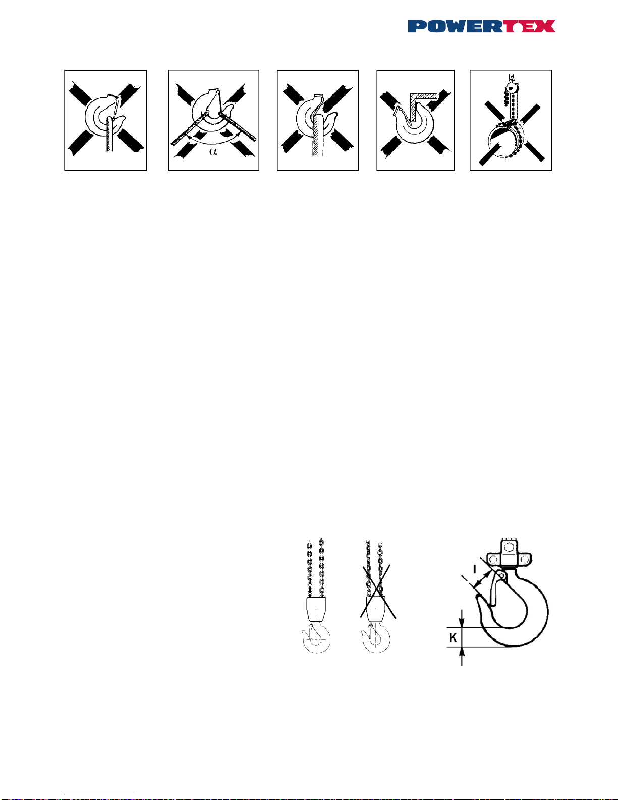
Kett-tali võib riputada sobiva kandevõimega tõsteaasa, seekliga, tala- või talakraanale. Kui kett on pingul, peavad mõlemad tõstekonksud verti-
kaalsuunal samal joonel asetsema.
NB! Tali plokile, konksudele või ketile ei tohi rakendada paindepingeid.
Tõstmine/langetamine
Kasutage üksnes sobiva kandevõimega tõste- troppe. Veenduge enne tõstmise alustamist, et last ei ole kinnitatud põranda/maapinna külge või
mingil muul moel kseeritud. Kontrollige et tõstekett ripuks vertikaalselt ja ketil ei oleks keerde sees. Ka käsikett peab olema heas seisukorras
ning vabalt juurdepääsetav. Lasti tõstmine või langetamine toimub käsiketti soovitud suunas tõmmates.
Hoiatus:
• Käsiketi tõmbamisel on lubatud kasutada üksnes ühe inimese käejõudu. Kui kett tundub liiga raskena, kasutage suuremat kett-tali või
vähendage koormust.
• Veenduge alati, et rippuva lasti all ei seisaks inimesi.
• Ärge astuge rippuvale lastile.
• Ärge tõstke ega langetage nii kaugele, et tõstekonks põrkub vastu tali korpust.
• Kett-tali ei tohi kasutada raskuste lohistamiseks.
• Talile ei tohi rakendada dünaamilisi pinged, mis tekivad näiteks olukorras, kus last kõrgemalt alla visatakse
• Ärge jätke tali sellel rippuva lastiga järelvalveta.
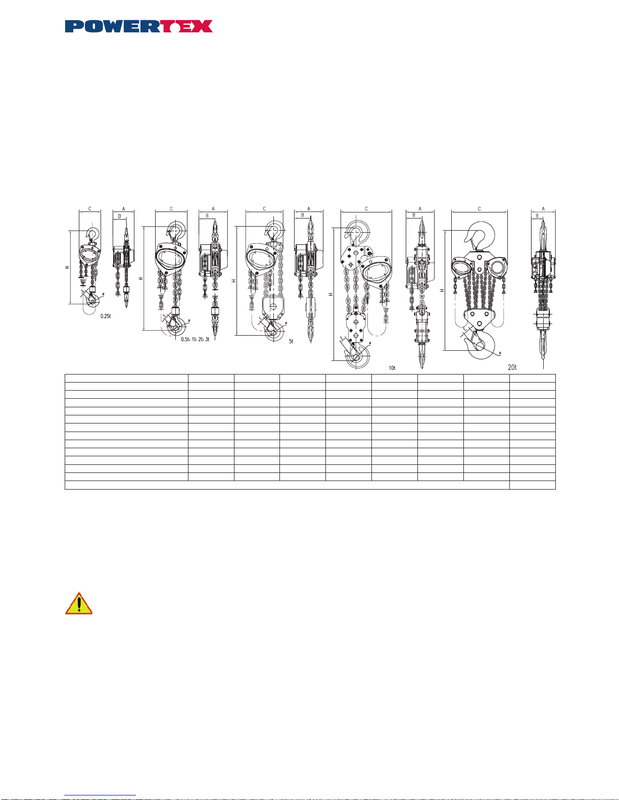
Mudel PCB-S1 PCB-S1 PCB-S1 PCB-S1 PCB-S1 PCB-S1 PCB-S1 PCB-S1
Maksimumkoormus tonni 0,25 0,5 1 2 3 5 10 20
Standardtõstekõrgus *) m 3 3 3 3 3 3 3 3
Tõstetrosside arv 1 1 1 1 1 2 3 8
Tõmbejõud käsiketile daN (kp) 19 21 29 36 41 40 54 2x40
Tõstekett 4x12 5x15 6,3x19,1 8x24 10x30 9x27 10x30 9x27
Mõõde A mm 106 128 142 175 195 183 195 183
Mõõde B mm 68 75 76 88 95 90 95 90
Mõõde C mm 108 130 150 185 226 255 355 577
Mõõde Ø mm 18 20 25 33 36 43 44 110
Mõõde E mm 20 22 26 35 37 43 47 70
Mõõde H min. mm 280 280 330 385 435 615 810 1.060
Kaal standardtõstekõrguse korral kg 6,4 8,9 12 19,5 29,4 36,3 64,1 185
*) Käsikett-tali pikkus varieerub vastavalt tõstekõrgusele.