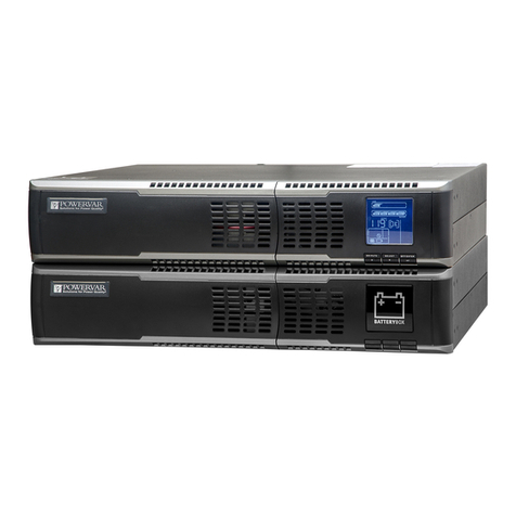
Powervar SG3K-2TXI Operation manual

POWERVAR Inc., 1450 Lakeside Drive, Waukegan, IL 6008
5, 1
-
800
-
369
-
7179, (PH#) 847
-
596
-
7000, (FAX) 847
-
596
-
7100
OWNER'S
OPERATING
MANUAL
Uninterruptible Power Supply Models:
Typeform: ABCDEF3000
Model: SG3K
-
2TXI

TABLE OF CONTENTS
UPS Features
1
ABCDEF Plus Online UPS Block Diagram
1
Important Safety Instructions (READ FIRST)
2
Chapter 1
ABCDEF PlusUPS Overview
3
True Regenerative Online Design
3
Input Power Factor Correction
3
Microprocessor Control
3
SNMP/HTTP Remote Management
3
Extended Battery Bank Option
3
Frequency Converter Option
3
Chapter 2
Installation Instructions
4
Dip Sw
itch Settings Diagrams
6
Extended Battery Bank Interconnection
7
Extended Battery Bank Installation Procedure
7
Chapter 3
Operation
8
Front Panel Indicators & Function Key Diagram
8
Front Panel Function Description
8
Audible Alarms
10
Category One Ala
rms
10
Category Two Alarms
10
Chapter 4
Rear Panel Details
11
Chapter 5
Communications Interfaces
12
RS
-
232 Interface (DB
-
9)
12
Communications Option Slot
12
Contact Closure & Opto Interface Options
13
Chapter 6
Maintenance & Technical Support
16
Care
& Maintenance
16
Battery Life vs. Temperature
16
Battery Replacement
16
Storing the UPS and Batteries
17
FCC Considerations
17
Technical Support & RMA Procedure
18
Requesting Technical Information or Support
18
Web Support
19
Warranty
19

1
ABCDEF
PLUS UPS FEATURES
True Double Conversion On
-
Line Design
Input Power Factor Correction
Wide Input Voltage Window
Pure Sinewave Output
Precision Output Voltage Regulation
SuperiorBrownout,SurgeandTransientProtection
Internal System Bypass
Eliminates
Generator Frequency & Voltage Drift
MicroprocessorControl&RS
-
232Communications
Monitoring & Shutdown Software Optional
Frequency Conversion
OptionalExtendedBatteryPacks&Chargers
Optional Internal SNMP/HTTP Interface Card
Two
-
Year Warranty
POWERVAR
ABCDEF PLUSON
-
LINE UPS SYSTEM
BLOCK DIAGRAM

2
IMPORTANT SAFETY INSTRUCTIONS
SAVE THESE INSTRUCTIONS
This manual contains important instructions which must be followed during the installation,
operation and maintenance of this UPS and its batteries. Pleas
e read all instructions before
operating this equipment and save this manual for future reference.
CAUTION
All of the models presented herein aredesigned for installation and use in a
temperature controlled environment, free of contamination.
CAUTION
This
UPSutilizesvoltage that may be hazardous. Do not attempt to disassemble.
This unitcontains no user replaceable parts.
Refer all servicing to POWERVAR.
THIS UPS IS NOT INTEND
ED TO BEUSEDINCONJUNCTIONWITH LIFE
SUPPORTOROPERATING
ROOM EQUIPMENT.
C
AUTION
AlwaysunplugthisUPSandremove theUPSbatteryfusepriortocleaningand
never apply liquid or spray detergent on the UPS.
CAUTION
Never attempt to service batteries.
High voltage exists within the unit, which
could cause electrical shock. Servi
cing of batteries should be performed or super
-
vised bypersonnel knowledgeable of batteries and therequired precautions. Keep
unauthorized personnel away from batteries. When replacing the UPS batteries,
use the same number and type of batteries.
IMPORTA
NT
Allow at least 24 hours, after theUPS is first installed and turned on, to fully charge
the internal battery and assure the maximum backup time is available.
DO NOT
DO NOT
plug this UPS into its own output as this may damage the UPS.
CAUTION
DO NOT
rem
ove or unplug the input cord when the UPS is turned on. This
removes the safety ground from the UPS and theequipment connected to the UPS.
CAUTION
This UPS contains its own energy source (batteries). The output receptacles
may carry live voltage even when
the UPS is not connected to an AC source.
IMPORTANT
Should any POWERVAR UPS unitbestoredformore than twoweeks, it is
mandatory thatthebattery fuse be removed prior to storage or battery
damage will result.

3
CHAPTER 1
POWERVAR UPS
-
Overview
True R
egenerativeOn
-
LineDesign
As new and innovative technologies have become thebackbone of today's businesses, maxi
mum
system availability is critical and downtime ismore expensive thanever. Increasingly, busi
nesses
needa UPSthatnotonlyprotects again
stblackouts,but also virtuallyeliminatesmore
frequent and
subtle power disturbances. Surges, sags, line noise and brownouts can disrupt
proper operation
of sensitive equipment. These disturbances mayalso create unnecessary pro
duction, service,
and da
ta recovery costs.
ATrue RegenerativeOn
-
Line UPS provides the highest level of protection against the widest
spectrum of power problems. The incoming AC utility source is converted to a regulated DC
voltage. Fromthis DC voltage, a new AC voltage isrege
nerated, providing continuous, clean,
tightlyregulatedpowertoyourequipment.Line
-
interactiveandOff
-
linedesignsleave yourequip
ment
connected directly to dirtyutility power. Theyonlyprovide minimal transient,voltage and
backup
protection. If y
our equipment operation is "Mission Critical", a true double conversion
On
-
Line
UPS from POWERVAR is the only clear choice.
Input Power Factor Correction
All POWERVAR ABCDEF Plus models include state
-
of
-
the
-
art Input Power Factor Correction.
This
greatly r
educes the amount of current demanded from your building wiring system, yielding
a
highly efficient, "building friendly" UPS.
Microprocessor Control
ThePOWERVARABCDEFPlusUPSincorporatesadvancedmicroprocessortechnology.This
technologymakes
possibl
e a high level of internal UPS control and management. Withthe
optional
software,thePOWERVARUPS’s support unattended shutdown,management,data
logging,
and self
-
diagnostics. The software supports MS Windows
®
95, 98, NT, 2000, 2000
Server, ME,
XP, Nove
ll Netware
®
5 & 6, LINUX and FreeBSD. UPSILON for UNIX supports
most popular
UNIX platforms and OS versions.
SNMP/HTTP Remote Management Support
Our SNMP/HTTP Agent board provides remote management and monitoring over anyEthernet
LAN, WAN or Internet util
izinga 10BaseT
-
type connection. Theoptional SNMP/HTTP agent
installs via an option slot located behind a cover plate on the back panel of every ABCDEF
Plus
model.
Extended Battery Bank Option
All POWERVAR ABCDEF Plus models have a continuous duty inverte
r and support the
addition of optional exter
nal battery/charger packs. Whether your application requires a few
additionalminutes orhours,
the POWERVARPlus UPS willbe ready.Optional batterycharger
upgrades forfaster rechargingarealso
available.
F
requency Converter Option
With a factory modification at the time of order, any POWERVAR ABCDEF Plus model can be
configured for use
as an international frequency converter. This makes the POWERVARPlus
UPS an ideal choice for
worldwide power applications
. Without this modification, all series
models will detect the
incoming utility line frequency and automatically set its output
frequency to match.

4
CHAPTER 2
INSTALLATION INSTRUCTIONS
1.
Verify the following is included in the UPS shipping carton:
(1) UPS,(1
) Power Cord &
(1) Owners Manual.
2.
Verify the UPS unit is configured for the proper input/output voltage and frequency. This
information is stated on the nameplate label located on the rear or the side panel of the
unit. If any special input plug and output
receptacle configurations were specified at the
time of order, verify for proper configuration.
3.
SetthedipswitcheslocatedontheUPSrearpanelforthenominalUPSoutput
voltage desired.
See the dip switch setting tables located on page 6.
Inmostcas
es thenominalUPS outputvoltageshouldbesettomatch theincomingutility
voltage. This will assure a close matching voltage in the event the UPS is placed on
bypass.
NOTE: Disregard the "ON" marking on the side of the actual dip switch
housing; use th
e tables in this manual or the silkscreen on the UPS rear panel only.
Dip switch 3 "enables" or"disables” the "Green Mode" function.
TheUPS isshipped
from the factory with the switch set in the "disabled" position (up). If SW3 is switched
down or to the
"enabled" position, the Green Mode function is activated. When the
load connected to the output of the UPS drops to under 10% of the full rated UPS output
for30 seconds, the UPSisautomatically placed into bypass and theinverter is turned off.
NOBATTE
RY BACKUP IS PROVIDED AFTER THE GREEN MODE HAS ACTIVATED.
Dip switch settings must be made while the UPS is turned off. Anychanges made while
the UPS is turned on will not take effect until the UPS is turn off and back on again since
the switch settings a
re read by the microprocessor onlyduring initial UPS power up.
4.
To prevent accelerated battery discharge during shipment, the 1
-
3Kva models have had
thebatteryfuseremoved.INSTALLTHEBATTERYFUSEPRIORTOTURNINGONTHE
UPSINPUTCIRCUITBREAKERORPLU
GGINGINTHEUPS.A poppingsoundmaybe
heard, which is normal.
CAUTION
NEVERREMOVETHEBATTERYFUSEORTURNTHEBATTERYCIRCUITBREAKER
OFF WHILETHE UPS AC CIRCUIT BREAKER IS TURNED ON AND OPERATING
FROMTHEUTILITYVOLTAGEORUPSDAMAGEWILLRESULT.
THEUPSMUSTBE
COMPLETELY SHUTDOWNPRIORTODISABLING THEINTERNAL BATTERY
SUPPLY.
CAUTION
In the event this UPS is to be turned off or stored for more than two weeks, the battery
fuse must be removed to prevent batterydischarge. If placed in long
-
term
storage,every
four months the UPS must be plugged in and turned on for 24 hours to allow the batteries
torecharge and prevent batterydamage.Failuretofollowtheseprocedures willinvalidate
your warranty.

5
5.
On 3Kva models the line cord is detachable
.
6.
S
elect a suitable location for the UPS near enough to the computer or equipment to
be protected. Connect the power cord(s) for the equipment to be protected to the
UPS
output receptacles.
VERIFY THE TABLE OR SURFACE SUPPORTING THE UPS WILL SUPPORT THE
WEIGH
T OF THE UPS AND ANY OPTIONAL EXTENDED BATTERY BANKS.
7.
If unattended computer shutdown and monitoring are desired, connect the optional
green
UPS/Computer cable to the DB
-
9 connector located on the UPS rear panel.
Then
install the shutdown and monitoring so
ftware provided with the UPS. For your
reference, UNIX shutdown and monitoring software is available at an additional cost.
8.
Verify the location selected has adequate ventilation to allow for the proper cooling of
the UPS.
DO NOT BLOCK UPS FANS OR AIR VENT
S. THE UPS MUST NOT BE
INSTALLED IN
AN
ENCLOSED AREA.
9.
Turn the input circuit breaker located on the UPS rear panel to the "on" position. The
internal UPS fan and front panel "line" indicator should turn on, followed by the
"bypass" LED, and after several s
econds, the "inverter" LED.
10.
Turn on the connected equipment and verify the UPS does not go into overload by
observing the front panel load indicator LEDs.
11.
The UPS, optional external battery bank(s) and additional chargers should be plugged
in and turned on
for 24 hours to charge the batteries. During this initial 24 hour
charging period, battery backup time may be substantially reduced.
IMPORTANT
TO TURN OFF THE UPS, SWITCH OFF THE INPUT CIRCUIT BREAKER
LOCATED ON THE UPS REAR PANEL AND PRESS THE ON/OFF
BUT
TON LOCATED ON THE UPS FRONT PANEL UNTIL THE UPS BEEPS.
THE UPS WILL RUN FOR ABOUT 30 SECONDS AND SHUTDOWN. DO NOT
PRESS THE ON/OFF BUTTON OR TURN THE CIRCUIT BREAKER ON AGAIN
DURING THE SHUTDOWN PROCESS OR THE UPS WILL GO TO
AN
ALARM
CONDITION, WARNING TH
AT THE UPS
WAS
NOT SHUTDOWN PROPERLY.
SHOULD THIS OCCUR, TURN OFF THE INPUT CIRCUIT BREAKER AGAIN AND
WAIT UNTIL THE UPS SHUTS DOWN.

6

7
TYPICAL EXTENDED BATTERY BANK & UPS INTERCONNECTION
(Mini
-
tower models shown; same applies for floor standi
ng banks)
2ND BATTERY BANK
1STBATTERY BANK
UPS
INSTALLATION PROCEDURE FOR EXTENDED BATTERY BANKS
1.
Remove the battery fuse located on the UPS rear panel. See illustration above.
2.
Locate the battery interconnect cable(s).
3.
Connect one end of the batt
ery interconnect cable to the UPS battery
connector. Connect theother end ofthe cable to thetop batteryconnector on the first
battery bank. See illustration above.
4.
Ifasecondbatterybankistobeconnected,connectoneendofthesecondbattery
inter
connect cable to the bottom battery connector on the first battery bank and
connect the other end of the cable to the top battery connector of the second battery
bank. (See illustration above)
5.
Follow the instructions in the proceeding step for additional b
attery banks.
6.
Reinstallthe battery fuse.
Apopping sound may be heard when inserting the fuse.
This is normal as the battery banks are pre
-
sharing the UPS.
7.
For allbatterybanks that have the battery charger option installed from the factory,
perform t
he following:
a.
Verify the battery charger circuit breaker is in the off (down) position.
b.
On the battery bank nameplate label located on the rear panel, verifythe
battery charger input voltage matches your utility source (120Vac or
230Vac).
c.
Connec
t the input line cord(s) to the battery bank(s) power inlet.
d.
Plug the other end of the power cord into a utility receptacle.
e.
Turn on the battery charger circuit breaker(s) (up).
f.
The batteries in the external battery banks are now being charged.
NOTE:
Int
ernal battery bank chargersdo not charge the batteries inside the UPS.
When the battery banks and UPS need to be shutdown for more than
two weeks, turn off the battery charger circuit breaker, disconnect the
interconnectingcablesandremovethebattery
fusefromtheUPSbatteryor
damage may occur.
TYPICAL
BATTERY
CONNECTOR
1ST CABLE
TO ADD MORE BANKS,
DAISY CHAIN TO NEXT
BANK FROM THIS
2ND CABLE
UPS
BATTERY
FUSE
OPTIONAL BATTERY
CHARGER CIRCUIT
BREAKER
OPTIONAL BATTERY
CHARGER CIRCUIT
BREAKER
POWER INLET FOR
OPTIONAL C
HARGER
POWER INLET FOR
OPTIONAL CHARGER

8
CHAPTER 3
OPERATION
UPS FRONT PANEL INDICATOR AND FUNCTION KEYS
1.
LOAD LEVEL INDICATOR LEDS
*The first or bottom LED is litwhen the output load is greater than 25% of the rated
output of the
UPS.
*The secondLED is litwhentheoutputload is greater than50%of theratedoutput
of
the UPS.
*The third LED is lit when the output load is greater than 75% of the rated outputof
the UPS.
2.
BATTERY LEVEL INDICATOR LEDS
*The third or top LED is lit
when the battery is fully charged.
*The secondLED is litwhenthebatterylevel isabovethelowbatterywarning
Level.
*The first LED is lit when the battery level is above the battery cutoff voltage.
3.
LINE / SITE WIRING FAULT INDICATOR LED
It is n
ormal for this LED to flash with 208 and240 volt domestic models asthese
voltages are normally LINE to LINE, without a neutral.
4.
B A T T E R Y M O D E I N D I C A T O R L E D
This LED is lit when the unit is operating from battery.
6
7
5
9
10
2
1
8
3
11
4

9
5.
BYPASS INDICATOR LED
When this LED is lit
the UPS bypass is active. Shouldthe Alarm LED be lit at the
same time, the UPS detected an internal failure and the UPS must be serviced.
6.
INVERTER INDICATOR LED
When this LED is lit,the UPS inverter is operating and powering the connected load.
7.
GREEN MO
DE LED INDICATOR
This LED is lit when the connected output load of the UPS drops to under 10% of
the full rated output of the UPS, providing SW3 is in the "down" position (Green
Mode Enabled) as shown on page 7. TheUPS isautomatically setto bypass mode
and the inverteris turnedoff, reducingthepower requirement.
NO BATTERY
BACKUP ISPROVIDED IN THIS MODE.
(TheUPSisshippedfromthefactorywith
SW3 in the "up" or disabled position.)
8.
OVER CREST INDICATOR LED
This LED lights when the connectedload ge
tting close to the peak current rating of
the UPS.
9.
ALARM INDICATOR LED
This LED is lit during the following conditions:
a.
The inverter voltage is too high or low.
b.
UPS over
-
temperature condition.
c.
The battery voltage is too high.
d.
The internal DCBus has an
underor over voltagecondition.
e. The internal microprocessor memory has failed.
10.
ON / OFF BUTTON
The following describes the different modes of operation for this button:
a.
Pressing this button when the UPS is off, and the utility voltage is not pre
sent, or
with the UPS input circuit breaker in the off position, will cause the UPS to DC
start and run oninternal batteryuntiltheON/OFFbuttonispressed again.
b.
Pressing this buttonwhile the UPS is on, and utility is present,will place the UPS
into
bypass mode.
c. Pressing this button when with the UPS input circuit breaker off, or when the utility
voltage is not present,
will turn off the UPS.
TO TURN UPS ON:
CONNECT THE UPS TO UTILITY POWER AND TURN ON
THE
MAIN CIRCUIT BREAKER LOCATED ON THE REAR P
ANEL. DO NOT
PRESS THE “ON” BUTTON LOCATED ON THE FRONT PANEL OR THE UPS
WILLBEPLACED
INTO BYPASS MODE.
TO TURN UPS OFF:
TURNOFFTHEMAINCIRCUITBREAKERLOCATEDON
THEREARPANEL ANDPRESSTHE"ON/OFF"BUTTONUNTIL THEUPSBEEPS
AND
WAITFOR THEUPSTO
SHUTDOWNAND TURNOFF(ABOUT30
SECONDS).
11.
TEST BUTTON
The following describes the different modes of operation for this button:
a.
Pressing the Test button while in Green Mode will disable Green Mode.
b.
Pressingthe Test button while utility is present w
ill put the UPS through a self test
diagnostic.
c. Pressing the Test button while in battery mode will turn the battery Audible alarm
off. Pressing it again will turn the Audible alarm back on.

10
AUDIBLE ALARMS
Audible alarm signals are divided into two dif
ferent levelsof alarm status. Category one
alarms representnormal or correctable operational alarms. Category two alarms are
sounded in the event of abnormal operation.
1.
Categoryone alarms:
a.
Two short beeps followed by three short beeps.
Notifies the
user that the UPS is configured with the optional battery
pack
and is in BATTERY MODE.
-
-
-
-
-
=UPS IS IN BATTERYMODE
b.
A continuous short beep.
The UPS is operating from battery and is in a LOW BATTERY operation.
..............
=UPS IS IN A LOW BATTERY CONDITION
c.
One l
ong beep prior to a short beep.
TheUPSisinanOVERLOADED,OVERCRESTCONDITION.Remove
some load from the UPS output to correct this condition.
--
-
=UPS IS IN OVERLOAD OR OVER CREST
d.
One short beep is sounded when either the ON/OFF or TEST buttons are
pressed and held. This notifies the user the associated actions have been
initiated by the UPS.
-
= WHENUPS FRONT PANEL ON, OFF AND TEST BUTTONS ARE DEPRESSED.
e.Oneshortbeepissounded whentheSELF
-
TESTbuttonhasbeenpressed and
held. This notifies
the self test has been started.
-
= WHENUPS FRONT PANEL TEST BUTTON DEPRESSED.
2.
Categorytwoalarms:
a.
Three short beeps indicate the UPS output voltage isout of proper
operating range.
-
-
-
=UPS OUTPUT VOLTAGE IS OUT OF PROPER RANGE.
b.
Fourshortbeeps
indicatetheUPSoutputfrequencyisoutofproper
operating range. The UPS must be repaired.
-
-
-
-
=UPS OUTPUT FREQUENCY IS OUT OF PROPER RANGE.
c.
FiveshortbeepsindicatetheUPSisinanover
-
temperaturecondition.
Check
for proper UPS cooling fan oper
ation or blockage.
.......
=UPS INTERNAL TEMPERATURE IS TOO HIGH.
d.
Shouldtheinternal POWERUPSELF
-
TESTfail,theUPSwillsoundthe
following alarms denoting the failure mode:
*Acontinuousrapidbeepingforabout5seconds,thentheUPSshuts
down
-
The UPS
output voltage is out of range.
...
= UPS OUTPUT VOLTAGE IS OF RANGE.
*A continuous rapid beepingfor about2 seconds andthe UPSshuts
down
–
The UPS performed a DC start, but there is no output
frequencysetin
the UPS memory. Plugthe UPS into your local
utility power and turn the
UPSonto setitfor your local utility power frequency.
........
= The UPS performed a DC start, but there is no output frequency set in
memory. Connect the UPS to your local utility power and turn on the UPS. Your local
utilityfrequ
ency is now set into the UPS memory. The next time the UPS is DC Started,
itsoutput
frequency will be set automatically.

11
Output Configuration
The 3Kva model provides three galvanically isolated 240Vac and 120Vac outputs. The two
120Vac receptacles
are derived split phase from the isolated, center tapped 240Vac output.
The center tap has been grounded to provide a derived neutral for both 120Vac outlets. Due
to this, the 120V load is divided between the two 120Vac receptacles. The
combined load
on a
ll outputs must never exceed 2100 watts.
MAIN POWER SWITCH &
INPUT CIRCUIT
BREAKER
120Vac OUTPUT
RECEPTACLES
Typical Rear Panel Overview
208
-
240Vac
RECEPTACLE
OUTPUT FUSES
(2) PLACES

12
CAUTION
When making a connection between a computer and the UPS RS
-
232port,
always use the green cable supplied with the UPS.
CAUTION
Therearecommunications optionsthat
WILLDISABLE
theRS
-
232portand
rende
r it inoperable. The options are as follows:
a.
Internal SNMP/HTTP agent option installed into the UPS
communications option slot.
The following options
WILL NOT
affect the operation of the RS
-
232 port:
a.
OptoCouplerbased signalinterfaceboard installed t
othe
communications option slot.
b.
Anyrelay based,drycontact signal interfaceboardinstalled
into the communications option slot.
CAUTION
DB
-
9Signals are not isolated and intended for connection to like RS
-
232
interfaces. DO NOT APPLY ANY OTHERVOLTAGE
STOTHESEPINS!

13
DRY CONTACT & OPTO COUPLER INTERFACE BOARD OPTIONS
Typical Dry Contact Relay Board
PIN & JUMPER ASSIGNMENT FOR THE
UA88374 RELAY OPTION BOARD
(no on
-
bypass signal)
PIN & JUMPER ASSIGNMENT FOR THE
UA88376 RELAY OPTION BOARD
(with on
-
b
ypass signal)

14
Typical Opto
-
coupler Interface Card
PIN ASSIGNMENT FOR THE
UA88373 OPTO
-
COUPLER OPTION BOARD
(no
-
bypass signal)
OPTO Board Internal Circuitry

15
APC Style Dry Contact Relay Board
PIN & JUMPER ASSIGNMENT FOR THE
UA88377 RELAY OPTION B
OARD
(APC Style Board)

16
CHAPTER 6
Maintenance & Technical Support
1.
Care
&
Maintenance
POWERVAR UPSs are designed to be maintenance
-
free. They can be
cleaned with a damp cloth or non
-
abrasive cleanser, providing the UPS is
turned off and the input plug is
disconnected from the utility source.
On a regular basis, check the vents to make sure they are kept free from
accumulation of dust, dirt or lint.
2.
Battery Life vs. Temperature
For full battery life, keep the UPS close to an ambient temperature of 77°F.
Th
e batteries should never be exposed to temperatures below 40°F and above
104°F.
3.
Battery Replacement
This UPS contains sealed maintenance
-
free batteries (VRLA). When situated in
a typical office environment, with the proper charging and limited cycling,
the
batteries can last many years.
In home, office or computer room
environments, the batteries should be replaced every three to five years.
Should you require battery replacement contact POWERVAR TECHNICAL
SUPPORT (see page 18 for contact information).
W
ARNING
Never attempt to service batteries. High voltage exists within the unit, which
could cause electrical shock.
Servicing of batteries should be performed or
supervised by personnel knowledgeable of batteries and the required
precautions.
Keep unauthor
ized personnel away from batteries.
When replacing the UPS batteries, use the same number and type of batteries.
NEVER
A.
NEVER
dispose of batteries in a fire, as batteries will explode.
B.
NEVER
dispose of used batteries or the UPS in the trash or a landfill as
it is
against federal and state laws.
The UPS and Batteries must be recycled.
For UPS and battery recycling information, please contact our service
department for the name and address of the nearest battery recycling facility.
CAUTION
A.
Do not open or muti
late the battery or batteries. Released electrolyte is
harmful to the skin and eyes. It may be toxic.
B.
A battery can present a risk of electrical shock and high short circuit current.
REFER ALL BATTERY SERVICING OR REPLACEMENT TO A QUALIFIED
SERVICE TECHNIC
IAN. NEVER ATTEMPT TO REPLACE THE BATTERIES
YOURSELF.

17
Thefollowingprecautionsshouldbeobserved byaqualifiedtechnicianwhen
working with batteries.
1.
Remove watches, rings, or other metal objects.
2.
Use tools with insulated handles.
3.
Wear rubber gloves a
nd boots.
4.
Do not lay tools or metal parts on top of batteries.
4.
Storing the UPS and Batteries
Should you need to store the UPS for a long period,fullyrecharge the battery
just prior to storage and recharge the batteryevery 4 months by plugging the
UPSin
to a power outlet. It is recommended that thebatteries charge for 24
hours after long
-
term storage.
5.
FCC Considerations
This equipment generates and uses radio frequency energyand if not installed
and used properly in strict accordance with the manufactur
er's instructions,
maycause interferencetoradio andtelevisionreception.All modelscoveredin
this manual have been tested and foundto comply with the limits for a Class A
computing device, in accordance with the specifications in FCC regulations,
Pa
rt 15, Subpart J, which are designed to provide reasonable protection
against such interference.
If thisequipmentdoes causeharmful interferenceto radio or television
reception, which can be determined by turning the equipment off andon, the
user is en
couragedtotry to correct theinterference by one or more of the
following measures:
a.
Reorient or relocate the receiving antenna.
b.
Increase the separationbetweenthe equipment and the receiver.
c.
Connect the equipment into an outlet on a circuit different fr
om that to
which the receiver is connected.
d.
Consultthedealeroranexperiencedradio/televisiontechnicianfor
assistance.

18
Your POWERVAR ABCDEF Plus UPS is backed by one of the finest customer
service teams
assembled. Write, call, fax or email should yo
u require
technical assistance
or service.
POWERVAR Inc.
1450LakesideDrive
Waukegan,IL60085
1
-
800
-
369
-
7179
(PH#) 847
-
596
-
7000
(FAX)847
-
596
-
7100
Please have your UPS model, serial numbers and dateofpurchase on hand
prior to your call. This informatio
n is located on the identification label on the
rear panel of the unit. This information is essential in retrieving your unit’s
historical records. Should our service department determine service is required,
you will be given a Return Material Authorizati
on number (RMA) along
with return shipping instructions.
The RMA number issued must appearonthe outside of the shipping carton.
The original shipping container must be used when returning any
Series
product. POWERVARwill not assume any responsibility fo
r shipping
damage.
In the event of shipping damage, you will be notified of the damage
and be
instructed tofile a claim with the freight carrier. You will be billed for all
repairs
causedbytheshipping damage.Youmustsubmitacopyofourrepair
invoic
e to
the carrier for reimbursement.
All units must be returned prepaid. The address and shipping instructions will
be given to you at the time the RMA is issued.
7.
RequestingTechnical Information orSupport
You may request technical information or suppor
t by email or telephone.
Please send your technical or support questions by email to:
CSERVICE@POWERVAR.COM
YoumaycontactaPOWERVARsupportengineerdirectlybycallingthe
POWERVARsupportlinebetween8:00a
mand5:00pmCST.
800.369.7179
Table of contents
Other Powervar UPS manuals

Powervar
Powervar ACDEF700-11 Operator's manual

Powervar
Powervar ACE Series User manual

Powervar
Powervar AMETEK 3300 Series User manual

Powervar
Powervar ACDEF6000-22 User manual

Powervar
Powervar Ace Plus Series User manual

Powervar
Powervar GTS Series User manual

Powervar
Powervar 3200 Series User manual

Powervar
Powervar ABCEG251 User manual

Powervar
Powervar ACE400 User manual

Powervar
Powervar Security Plus Operator's manual