P70626014V
lnstallation
WIREINSTALLATION
FROMTHESWITCH
TO
THE
CONTHOL
UNIT
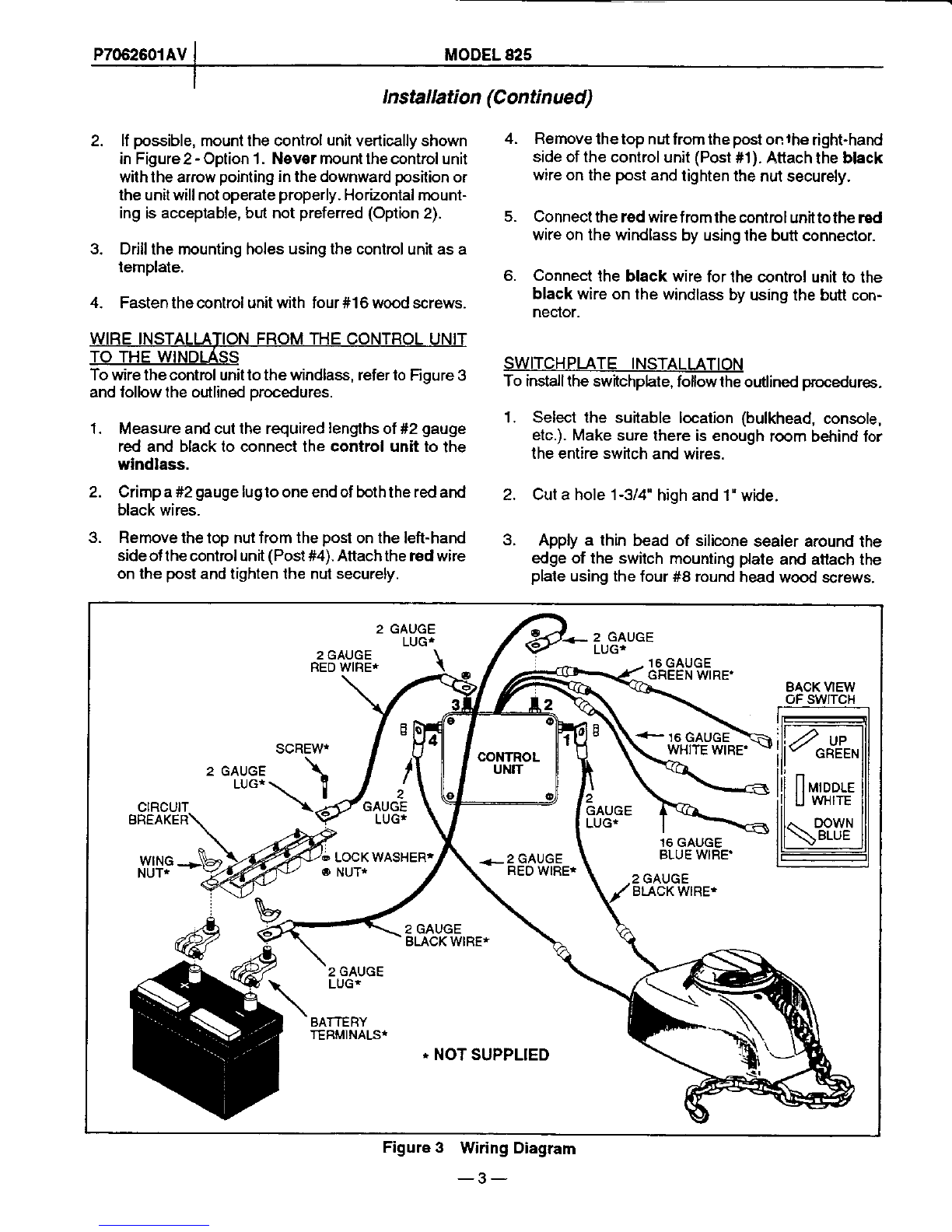
Towiretheswitchlothecontrolunil.refertoFioure3and
followtheoutlined
procedures.
1. Measureandcultherequired
lengths
of#16
gauge
green,
whileandbluewirestoconnecttheswitch
tothecontrcl unit.
2. Connectlhe #16gaugegreenwireto the grcen
wireonlheco?trol
unitand
thegreen
wireonthe
swilchusingbuttconneclors.
3. Connectthe#16
gauge
whitewiretothewhitewire
on
lhecontrolunitandthewhite
wireon
lheswitch
usingbuttconnectors.
3. Connecl
the#16
gauge
blue
wiretothebluewire
onthecontrolunilandthebluewire
onthe
switch
usingbunconneclors.
WIBEINSTALLATIONFROMTHECONTFOL
UNIT
TO THE BATTERY
Towirethecontfolunittothebattery,reierto Figure3
and
followthe
outlined
procedures.
1. Measureandcuttherequired
lengths
ol#2gauge
redandblackwirestoconneclthecontrol unitto
thebanory.
2. Crimpalf2gauge
lugtoallfourendsofthewires.
CAUTION
Never attach tho circuit breaker to the battery
ground terminal(negative
G)post).
3. Attachthecircuitbreakertothe
positive
(+)
sideof
thebattery.
4. Attachoneendoftheredwirelotheotherendofthe
circuitbreaker
byusinga 5/16'-18x 1' hexhead
screwwitha5/16'lockwasherandnut.
5. Removethetopnutfromthe
post
locatedtotheleft
ofthegreen,
whiteandbluewiresusedtoconnecl
theswilchtothecontrolunit
(Post
#3). Attachthe
redwireonthepost
and
tighten
thenut
securely.
Neverattachthe black wire to the batteryhot ter-
minal(positive(+) post).
6. Attachtheblackwirelothenegative
O sideofthe
batterv.
CAUTION Awnnxrue
MODEL
825
(Continued)
7. Rernovethetopnut
lrom
the
postlocatedtotheright
ofthe
green,
whiteardbluewiresused
loconnecllhe
switchtothe
controlunit
(Pos{
tt2).
Attachlheblack
wireonthe
post
and
tighlenthenutsecurely.
RODEINSTALLATION
Thewirdlassis
designedtoacceplanchorline,
chainor
acombinationolthetwo.Howaner.
itisimoortanlthatthe
rope-to-chain
splicebedoneconea!. Ashaclde
will not
fitthrough
thechain
gypsy.
Thewarranty
isinvalilatedif
ashaclde
isused.Useaneyesplbe
toatlachtheanchor
chainlotherope.This
prrcedure
shouldbedone
by
a
prolessional
atarnarina.However,complete
ropesplic-
ing
instnrclion
areavailableinChapnan
PibtingS@rnan-
shipand Snma
B@tHandling,Chales E.Clraprnan.
Use916" or U8"Acc@ proof
coil chainor 1/2"or
5/8"Powerwinchlineonly. Runthe chainthrough
thewindlassbeforesplicingto ensurethereis an
exactmatchbetweenthechain
andthe gypsy,
ANCHOR
ATTACHMENT
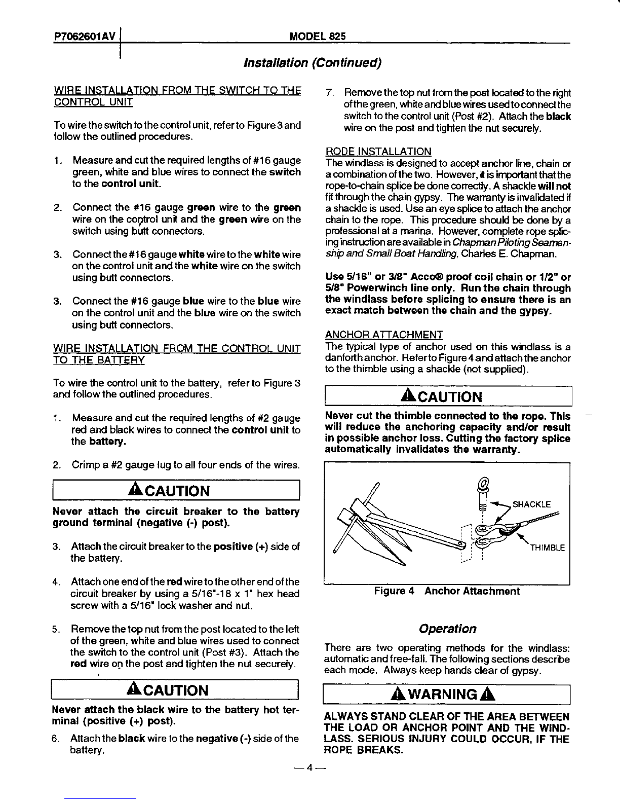
Thetypical
typeof anchorusedonlhiswindlassisa
danforthanchor.Referto
Figure4andattachthe
anchor
tothethimble
usingashackle
(not
supplied).
CAUTION
Nevercut the thimbleconnoctedto th€ rope.This
will r€dsce the anchoringcapacity and/or rosull
in possibl€
anchorloss.Cutting
the lactorysplice
automaticallyinvalidatesthe warranty.
tg
U
iSHACKLE
THIM8LE
Figure4 AnchorAttachment
Operation
There are two operating methods for the windlass:
automalic
andfree{all. Thefollowing
sectionsdescribe
eachmode. Alwayskeephandsclearof gypsy.
ALWAYSSTANDCLEAROFTHEAREABETWEEN
THE
LOAD
ORANCHORPOINTAND
THEWIND.
LASS,SERIOUSINJURYCOULD
OCCUR.IF
THE
ROPE
BREAKS.
-4-