__________________________________________________________________________________________________________________
European SafetySystemsLtd. Impress House,Mansell Road,Acton,London W37QH sales@e2s.com Tel:+44(0)2087438880
www.e2s.com Fax:+44(0)2087404200
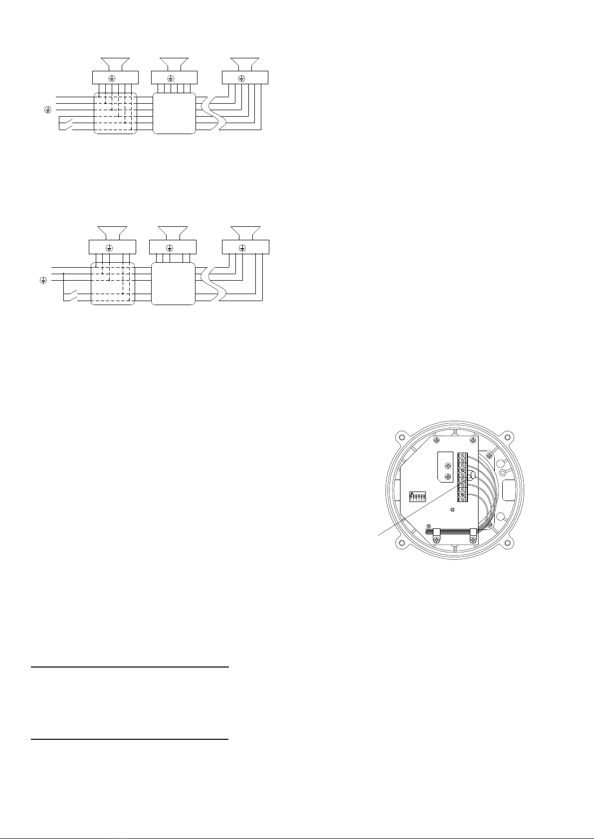
S3S2
Stage3
Stage2
L
N
C
C
NL LN CS2 S3 S3S2CNL
NOTE ifthe secondand third stagewiresarenotused theymustbe
individuallyinsulatedtoensurethat cannotmakecontacttoanyotherwires.
DC SOUNDERS
RedPositiveOrangeS2
BlackNegativeYellow S3
Green/YellowGround
S3S2
Stage 3
Stage2
+
-
-
+S2 S3 S3S2
NOTEifthe second and third stage wires are notused theymustbe
individually insulated toensure that cannotmakecontacttoanyother wires.
-
+-
+
POWERSUPPLYSELECTION
It isimportantthatasuitablepowersupplyisusedtorun the
sounders.Thepowersupplyselectedmusthavethe
necessarycapacitytoprovidetheinputcurrenttoall ofthe
soundersconnectedtothesystem.
Unit TypeInput Input@1kHzMax.
VoltageCurrentI/PVolts
E2xS112UL24VDC284mA30V
E2xS112UL48VDC146mA58V
E2xS112UL230V50/60HzAC54mA253V
E2xS112UL120V50/60HzAC104mA132V
TONESELECTION
TheE2xS112ULsoundershave45 different tonesthat can be
selectedforthefirststagealarm.Thesounderscanthenbe
switchedtosound second and thirdstagealarmtones.The
tonesareselectedby operation of aDIPswitchon thepcb for
bothDC and AC units.Thetonetableoppositeshowsthe
switch positions forthe45 tonesand whichtonesare
availableforthesecond and thirdstages.Tooperatethe
sounderon stageonesimplyconnectthesupplyvoltageto
theflying leads (Redand BlackandGreen/YellowforDC
units,Black,WhiteandGreen/YellowforAC units).
Theoperationofthesecond andthirdstagesisdifferentfor
DC and ACunits.
DC UnitsSecond andThirdStageToneSelection
Toactivatethesecond stage,remotelyswitchtheS2orange
wiretothenegativesupply.Toactivatethethirdstage,
remotelyswitchtheS3orangewiretothenegativesupply.
NOTE theDC power supplytotheRedandBlack wiresmust
bemaintainedfor2nd and3rd stages.
AC UnitsSecond andThirdStageToneSelection
Toselectthesecondandthirdstageson theE2xS112ULAC
sounderstheCommon(C)Violetwiremustberemotely
connectedtotheS2orangewireforthesecondstageandto
theS3yellowwireforthirdstage. NOTEtheACpower supply
totheBlackandWhitelead mustbemaintainedfor 2nd and 3rd
stages.
VOLUME CONTROL
Thevolumeon theE2xS112ULsoundercan besetusing the
volumecontrol (see figures2and 3). For maximum output level
thepotentiometer shouldbesettothefullyclockwiseposition.
WARNING –HIGHVOLUMEMAY CAUSEHARMTO
PERSONNELIN CLOSEPROXIMITY
END OFLINEMONITORING
OnE2xS112ULDC units,dcreverselinemonitoring canbe
usedifrequired.AllDC soundershaveablocking diodefittedin
theirsupplyinputlines.Anend oflinemonitoringresistor canbe
connectedacross the+veand –ve terminals.Ifan end ofline
resistorisuseditmusthavethefollowingvalues:-
24VDC Sounders
Minimum Resistance3k9ohmsMinimum wattage0.5W
Minimum Resistance1kohmsMinimum wattage2.0W
48VDC Sounders
Minimum Resistance15kohmsMinimum wattage0.5W
Minimum Resistance3k9ohmsMinimum wattage2.0W
Theresistor mustbeconnecteddirectlyacross the+veand–ve
terminalsas showninthefollowingdrawing.Whilstkeeping its
leads asshort aspossible,aspacingof atleast1/16 inch
(1.58mm) mustbeprovidedthroughairand over surfaces
betweenuninsulatedliveparts.
S3 S3 S2 S2 - - + +
E2xS112ULDCSounder
End ofLineResistor
G G
End ofLineResistor


