PowMr POW-LIO51 Series User manual

User Manual
POW-LIO51 Series

User Manual
POW-LIO51 Series
Table of Contents
1Overview............................................................................................................................................................ 1
1.1 Scope...................................................................................................................................................... 1
1.2 Intended Audience..............................................................................................................................1
1.3 Manual Usage ...................................................................................................................................... 1
2Product Introduction...................................................................................................................................... 2
2.1 Introduction..........................................................................................................................................2
3Safety Instructions.......................................................................................................................................... 2
3.1 Labeling Explanation ......................................................................................................................... 2
3.2 Installation Tools.................................................................................................................................. 3
3.3 Precautions........................................................................................................................................... 4
4Overview of Main Components...................................................................................................................6
5Product Introduction...................................................................................................................................... 7
5.1 Overview................................................................................................................................................ 7
5.2 Advantages........................................................................................................................................... 7
5.3 Product Appearance........................................................................................................................... 8
5.4 Port Panel..............................................................................................................................................9
6Principle and Structure................................................................................................................................11
6.1 Operating Principle...........................................................................................................................11
6.2 Connection Structure.......................................................................................................................11
7Battery Installation and Wiring .................................................................................................................12
7.1 Tool Preparation for Installation....................................................................................................12
7.2 Installation Preparation ...................................................................................................................12
7.3 Installation Notes..............................................................................................................................12
7.4 Installation Steps...............................................................................................................................13
7.5 Electrical Connection.......................................................................................................................15
8Debugging ......................................................................................................................................................17
8.1 RS485 & CAN Port Definition.........................................................................................................17
8.2 Upper Computer Software Operation Guide.............................................................................18
8.3 ADS DIP Switch Definitions ............................................................................................................21
8.4 Battery Parallel Connection DIP Switch Diagram .....................................................................23

User Manual
POW-LIO51 Series
8.5 Power-On Sequence ........................................................................................................................25
8.6 Common Issues and Solutions ......................................................................................................25
8.7 Inverter Matching Information ......................................................................................................28
9Maintenance...................................................................................................................................................30
10 Technical Specifications...............................................................................................................................31


User Manual
POW-LIO51 Series
1
1Overview
1.1 Scope
This user manual provides information, operating instructions, and maintenance guidelines for the
POW-LIO51200-150A low-voltage residential energy storage battery series. The POW-LIO51
residential energy storage series is a lithium battery system developed by PowMr, designed to be
compatible with various inverter brands available in the market.
1.2 Intended Audience
This manual is intended for professional technical personnel involved in the installation, operation,
and maintenance of lithium batteries, as well as end-users seeking technical information.
1.3 Manual Usage
1. Before using the product, carefully review this user manual and keep it in a readily accessible
location.
2. All information in this user manual, including images and symbols, is proprietary to PowMr.
Unauthorized use of any part or all of the content is strictly prohibited for individuals outside
the company.
3. Considering the potential for updates and corrections to the manual content, users are advised
to use the provided documentation as a reference. For the latest user manual, please refer to
the product documentation provided or contact customer service through the official website.

User Manual
POW-LIO51 Series
2
2Product Introduction
2.1 Introduction
1. The POW-LIO51 residential energy storage series is a battery module developed by PowMr for
low-voltage lithium battery systems, primarily applied in the field of residential energy storage.
It can achieve high-precision multi-cell voltage and temperature acquisition.
2. The module adopts a passive balancing method, with a maximum balancing current of up to
300mA, improving the overall lifespan of the battery pack.
3. The module features external communication interfaces using CAN, RS485, and dry contact
communication methods, allowing communication in parallel for up to 16 batteries.
4. Embedded BMS system effectively monitors phenomena such as over-temperature, over-
voltage, and over-current, reducing the risk of battery damage or even fire, ensuring the safety
of life and property.
5. This manual introduces the types, sizes, performance, technical characteristics, warnings, and
precautions of lithium battery systems. This specification is only applicable to the battery
systems provided by PowMr.
3Safety Instructions
3.1 Labeling Explanation
To ensure user safety during product use, relevant labeling information with appropriate symbols
is provided in this manual. The following lists symbols that may be used in this manual, so please
read carefully.
Icon
Description
Signifies a low-level potential hazard. Failure to avoid may result in minor or
moderate injury to personnel.
Indicates the presence of high voltage inside the battery module. Touching may
lead to electric shock hazards.
This is the ground protection port (PE). It should be securely grounded to
ensure the safety of operating personnel.
User Manual
POW-LIO51 Series
3
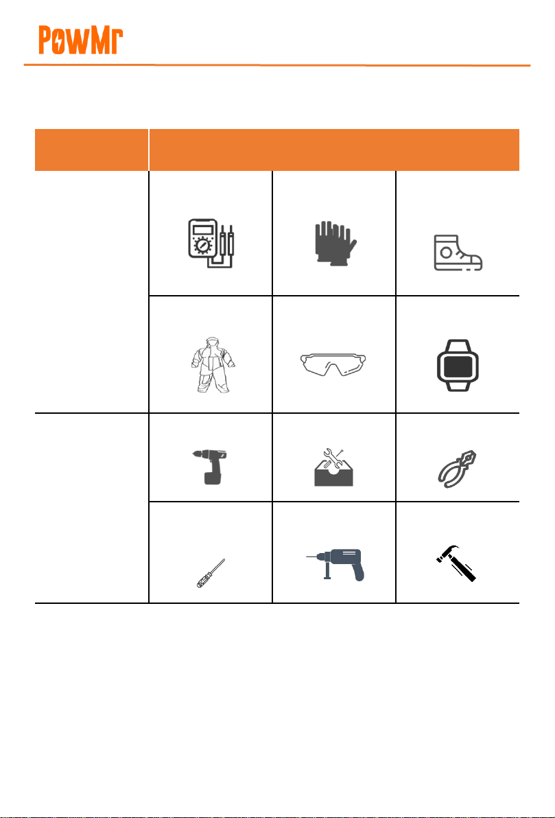
3.2 Installation Tools
Prior to installation, prepare the following tools:
Category
Tools
General Tools
Multimeter
Protective gloves
Insulated safety
shoes
Protective clothing
Safety goggles
Antistatic wrist strap
Installation Tools
Electric screwdriver
Socket wrench
Wire stripper
Phillips screwdriver
(M4/M6)
Electric drill
Hammer

User Manual
POW-LIO51 Series
4
3.3 Precautions
3.3.1 Manual Storage
1. This manual covers crucial information for the POW-LIO51 Home Energy Storage Series. Prior
to operating the product, carefully read this manual as it provides essential assistance in
acquainting you with the product.
2. Store this manual securely for the convenience of relevant installation and maintenance
personnel to refer to during operations.
3. Strictly follow the descriptions in this manual when operating the PowMr Home Energy Storage
Series to avoid equipment damage, injuries, property loss, and other potential issues.
3.3.2 Label Protection
1. Warning labels on the POW-LIO51 Home Energy Storage Series contain crucial safety
operation information. It is strictly prohibited to intentionally tear or damage them!
2. The product has a nameplate on the casing, providing essential parameter information. It is
strictly prohibited to intentionally tear or damage it!
3.3.3 Safety Warning Labels
When conducting installation, routine maintenance, inspections, etc., on the POW-LIO51 Home
Energy Storage Series, to prevent unauthorized individuals from approaching, engaging in
improper operations, or accidents, adhere to the following conventions:
1. Erect clear signage at the switch locations of the PowMr products to prevent accidents caused
by accidental closing.
2. Set warning signs or establish safety warning tape near the operating area to prevent unrelated
personnel from approaching.
3. After maintenance or inspection, conduct a thorough on-site safety check.
3.3.4 Personnel Requirements
1. Only personnel with relevant professional qualifications are allowed to perform various
operations on this product.
2. Operating personnel should be thoroughly familiar with the composition and working
principles of the entire POW-LIO51 Home Energy Storage Series system.
3. Operating personnel should be fully acquainted with the "User Manual" for this product.

User Manual
POW-LIO51 Series
5
3.3.5 Power-On Measurement
After the energy storage battery is installed, there is a high voltage present, and accidental contact
with the positive and negative terminals may result in electric shock injuries. Therefore, when
conducting power-on measurements, attention should be paid to the following:
1. Take necessary insulation protection measures (such as wearing insulated gloves).
2. Accompanying personnel must be present to ensure personal safety.
3.3.6 Measuring Instruments
When performing electrical connections and trial operations on the energy storage backup battery,
and to ensure that electrical parameters meet requirements, relevant electrical measuring
equipment such as multimeters, power meters, etc., should be used. Note the following:
1. Use measuring equipment with a suitable range that conforms to on-site working conditions.
2. Ensure the correct and standardized electrical connections of the instruments to avoid dangers
such as electric arcs.
3.3.7 Maintenance and Inspection
When both the energy storage battery and the inverter are turned off, and electrical connections
are confirmed to be disconnected, maintenance or inspection operations can be carried out on
the energy storage battery cabinet. Pay attention to the following:
1. Ensure that the energy storage battery will not be accidentally re-energized.
2. Use a multimeter to ensure that the energy storage battery is completely de-energized.
3. For parts near potentially live components during operations, use insulating materials for
insulation covering or grounding.
4. It is strictly prohibited to perform maintenance or inspection operations on live equipment!
When performing maintenance or inspection on equipment, it must be ensured that at least
two personnel are present at the site. Maintenance operations can only be carried out after the
equipment is safely de-energized, fully charged, or discharged.
User Manual
POW-LIO51 Series
6
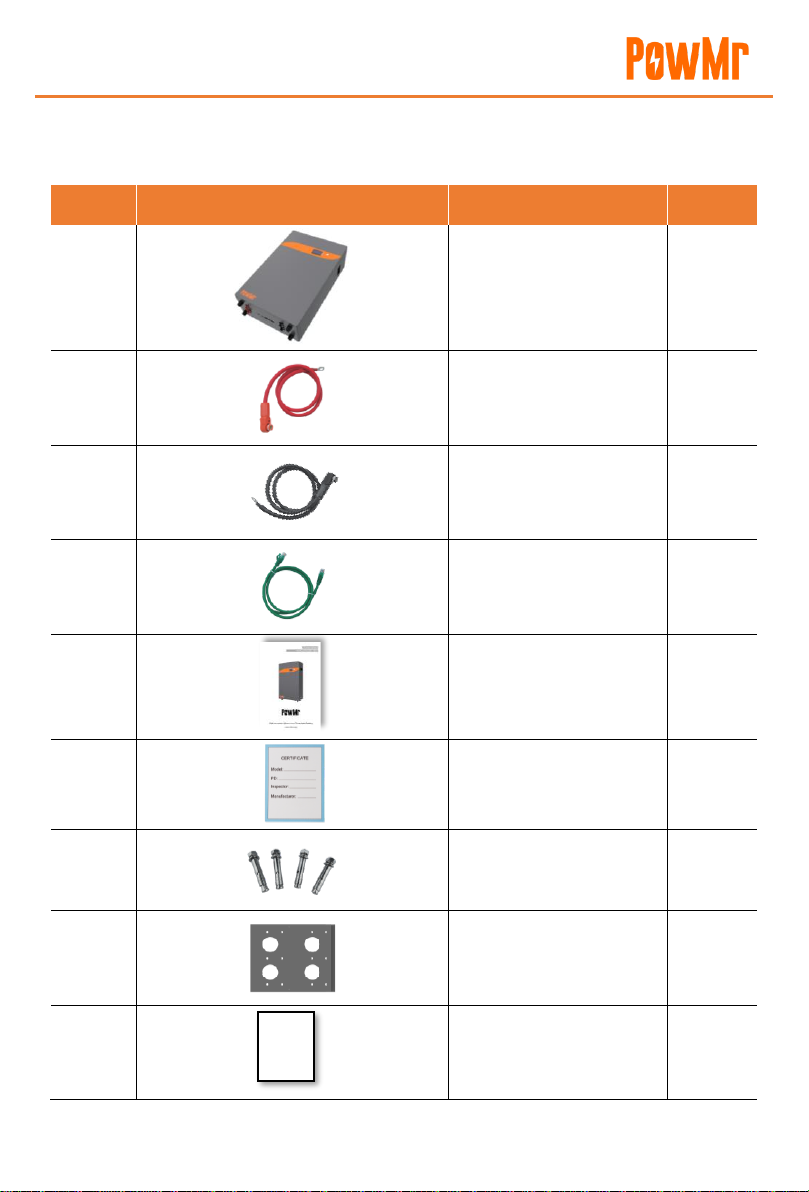
4Overview of Main Components
No.
Image
Name
Quantity
1
Battery
1
2
Red-Positive Power Line
1
3
Black-negative Power Line
1
4
Communication Cable
1
5
Product User Manual
1
6
Certificate of Conformity
1
7
Expansion Bolt
9
8
Wall Mount Bracket
1
9
Warranty Card
1
Warranty
Card

User Manual
POW-LIO51 Series
7
5Product Introduction
5.1 Overview
The POW-LIO household energy storage series lithium battery module integrates PowMr's high-
capacity, high-safety lithium iron phosphate battery cells. It adopts a stacked design with
advantages in footprint and vertical space utilization. The module incorporates a high-precision
Battery Management System (BMS) unit, monitoring and collecting real-time data on voltage and
temperature inside the module. This enables intelligent temperature control at the cell level and
smart cell balancing, enhancing system efficiency and battery cycle life. The module features a
shock-resistant structure within a cold-rolled sheet metal shell for high safety and reliability,
meeting household standards. Additionally, the module is designed for high stability and
disturbance resistance, ensuring the safe and reliable operation of the battery system.
5.2 Advantages
⚫The positive electrode material of the battery is lithium iron phosphate (LiFePO4) material,
which has good safety performance, has a cycle life of more than 6,000 times.
⚫The high-performance intelligent management system is adopted to realize comprehensive
state control of battery charging, discharging, floating charging and hibernation, and multi-
level protection is set for voltage, current, temperature, etc., so that the battery is always in an
ideal state.
⚫It has a comprehensive monitoring system to monitor the voltage, current, temperature,
capacity and working status of the battery.
⚫The system adopts an intelligent design method to meet the four remote control standards of
the national standard: telemetry, remote signaling, remote control, and remote adjustment.
⚫Built-in intelligent balance module to ensure the capacity consistency of the battery pack
during long-term use and prolong the service life.
⚫The control panel includes status display and alarm devices, which can visually see the working
status and alarm information of the battery.
⚫The system has its own intelligent thermal management device, which can work in a wide
temperature range.

User Manual
POW-LIO51 Series
8
5.3 Product Appearance
1
LCD Screen
4
Bottom Port Panel
2
Function Keys
5
Installation Backplate
3
Base
6
Handle

User Manual
POW-LIO51 Series
9
5.4 Port Panel
No.
Name
Function
Notes
1
Positive Terminal Port
(+)
Battery Positive Output
2
Negative Terminal Port
(-)
Battery Negative
Output
3
Reset Button (RST)
Battery Reset
Briefly tap and release within
1-3 seconds.
4
Operation Light (RUN)
Battery Operation
Indicator Light
5
Alarm Light (ALM)
Battery Alarm Indicator
Light
6
Capacity Light
(CAPACITY)
Battery Capacity
Indicator Light
7
Dry Contact
Dry Contact
Communication
1. Dry Contact 1 - PIN1 to
PIN2: Normally open,

User Manual
POW-LIO51 Series
10
closed during fault
protection;
2. Dry Contact 2 - PIN3 to
PIN4: Normally open,
closed during low battery
alarm.
8
RS485A
485 Communication
Interface
Communication with inverter
via RS485
9
CAN
CAN Communication
Interface
Communication with inverter
via CAN
10
RS232
1. Monitor batteries
and modify
parameters.
2. Perform software
upgrades.
11/12
RS485B
Communication
between batteries.
Functions are the same, no
distinction between left and
right.
13
Ground Terminal Port
Battery Ground
14
DIP Switch (ADS)
Define Battery
Communication Code

User Manual
POW-LIO51 Series
11
6Principle and Structure
6.1 Operating Principle
Working principle for Residential Lifepo4 Battery Energy Storage System: Connect battery pack in
parallel to the DC output end of the inverter of the energy storage device. When the mains power
supply is normal, the inverter module works normally to supply power to the equipment (the load
in the figure) and charge the battery pack; when the utility power and photovoltaic power are cut
off, the battery pack provides uninterrupted power supply to the inverter to ensure the normal
operation of household electricity; When power is turned on again, the battery pack is charged
while power is restored to the household loads.
6.2 Connection Structure
The connection diagram of residential lifepo4 battery energy storage system is shown in Figure 1
below:

User Manual
POW-LIO51 Series
12
7Battery Installation and Wiring
7.1 Tool Preparation for Installation
Tools Required: Electric drill, hammer, wrench, M8*60 expansion bolt, Phillips screwdriver,
multimeter, insulated gloves, Ethernet cable, power cable.
7.2 Installation Preparation
Safety Regulations
The installation, operation and maintenance of LiFePO4 Battery Energy Storage System should
only be carried out by trained and qualified professionals. Before installation and use, please read
the safety precautions and related operating procedures of this product carefully. The installation
process must strictly abide by the following safety regulations and local safety regulations,
otherwise it may cause personal injury or product damage.
➢Please ensure that the inverter connected to the battery is a qualified power system;
➢When installing the battery, please ensure that the power system is turned off and the battery
pack is turned off;
➢All power-saving cables must have corresponding insulation measures, and it is strictly
forbidden to expose the power cord;
➢Ensure that the battery and the power system are reliably grounded during installation.
7.3 Installation Notes
⚫When begin to install the battery system, you should pay attention to the following matters:
⚫Installation space and load bearing. Make sure that there are sufficient fixed components to
install the battery system, and to ensure that the battery mounting bracket or the cabinet be
strong enough to bear the weight.
⚫Cable specifications. To ensure that the use of the connection of the power supply line can
meet the maximum current requirements of equipment operation.
⚫Project layout. Ensure the whole construction process of power equipment, batteries and other
reasonable layout.
⚫Wiring layout. Ensure that the wiring reasonable, orderly; and consider the moisture-proof,
corrosion prevention.

User Manual
POW-LIO51 Series
13
⚫The whole installation process should wear anti-static wristband.
⚫The installation site should be at least two or more peoples to operate.
⚫Please ensure the installation site safe before installation.
7.4 Installation Steps
The battery installation steps are shown in table below:
⚫Select a suitable solid wall with a thickness greater than 150mm;
⚫Refer to the fixing distance of the mounting bracket bolts, and mark the hole position on the
wall;
⚫Drill 9 holes according to the hole position, the depth is ≥80mm;
⚫Mount the M8 expansion bolts in the upper holes and screw on the nuts;
⚫Fix the mounting bracket on the wall with expansion bolts;
⚫Under the condition of keeping the battery vertical, raise the battery to a position slightly
higher than the mounting bracket, and hang the battery on the mounting bracket.
Step No.
Name
Definition
1
Turn off power supply
The system should be powered off, to ensure that
there is no electric in installation process
2
Mechanical installation
1. Mounting lugs installation
2. Battery fixed installation
3
Electrical installation
1. Grounding cable
2. Power cable installation
3. Connecting equipment installation
4. Communication cable installation
4
Electrical commissioning
Power system commissioning
Step 1. Interruption Of Power Supply
Before installation, please ensure the battery is powered off, at the same time, shutdown the
equipment which need to connect to the battery.
Step 2. Machinery Installation
1. Installation of the mounting bracket. The device is packaged with an attached mounting wall
bracket. Before installing the battery, fix the mounting bracket on the wall to ensure that the
installation is tight.

User Manual
POW-LIO51 Series
14
2. Fixed battery installation. Secure the battery module to the mounting bracket to ensure that
the battery pack is securely installed.
3. Expansion bolt installation diagram.
NOTICE:
1. In order to avoid electric shock or other injuries, check whether the existing electronic
plumbing installation is compliant before drilling.
2. The battery is heavy, please handle it with care, so as not to damage the product or injure
the installer.
Wall bracket
Battery pack

User Manual
POW-LIO51 Series
15
7.5 Electrical Connection
➢Single Unit Wiring:
Step 1. Connect the positive and negative terminals of the battery to the positive and negative
terminals of the inverter using the power cable.
Step 2. Complete the battery's grounding connection by using the ground wire.
Step 3. Connect the RS485A (or CAN) port of the battery to the RS485 (or CAN) communication
port of the inverter using the communication cable.
Step 4. If used as a single unit, set the ADS dip switch to 1. Refer to section 8.3 for dip switch
rules.
➢Parallel Wiring:
Step 1. If multiple batteries are used in parallel, manually press the low-voltage switch (ON/OFF)
first. Use a multimeter to check if the voltage of each battery is consistent. If consistent,
turn off the batteries and proceed with cable connections, as shown in the schematic
diagram (using two batteries in parallel as an example).

User Manual
POW-LIO51 Series
16
Step 2. Connect the positive terminal of the battery using the power cable, and then connect the
negative terminal of the battery using the power cable.
Step 3. Connect the RS485B communication interface of adjacent batteries with communication
cables (RS485B battery parallel ports have the same functionality and are not
distinguished).
Step 4. Connect the ground wire to the grounding point for all batteries. There is a ground symbol
in the lower-left corner of the battery; attach the ground wire terminal to this point.
Step 5. Use a standard Category 6 cable. Connect one end to the RS485A (or CAN)
communication interface of the battery and the other end to the RS485 (or CAN) interface
of the inverter (Note: the pin definition of the inverter communication should match that
of the battery; refer to section 8.3 for battery-to-inverter pin definitions).
Step 6. Connect the positive terminal (+) of the first battery to the positive terminal interface of
the inverter using the power cable. Then, connect the negative terminal (-) of the last
battery to the negative terminal interface of the inverter using the power cable.
Note
⚫The battery directly connected to the inverter via the communication cable is defined as
the host. The host dip switch is set to 1 and needs to be switched before powering on.
⚫Define dip switches for other batteries sequentially from 2 to 15. Avoid duplicating dip
switch settings to 1.
Other manuals for POW-LIO51 Series
1
This manual suits for next models
1
Table of contents
Other PowMr Batteries Pack manuals


