PowMr POW-LIO51 Series User manual


User Manual
POW-LIO51 Series
Table of Contents
1Overview............................................................................................................................................................. 1
1.1 Scope...................................................................................................................................................... 1
1.2 Intended Audience..............................................................................................................................1
1.3 Manual Usage ...................................................................................................................................... 1
2Product Introduction...................................................................................................................................... 2
2.1 Introduction..........................................................................................................................................2
3Safety Instructions.......................................................................................................................................... 2
3.1 Labeling Explanation ......................................................................................................................... 2
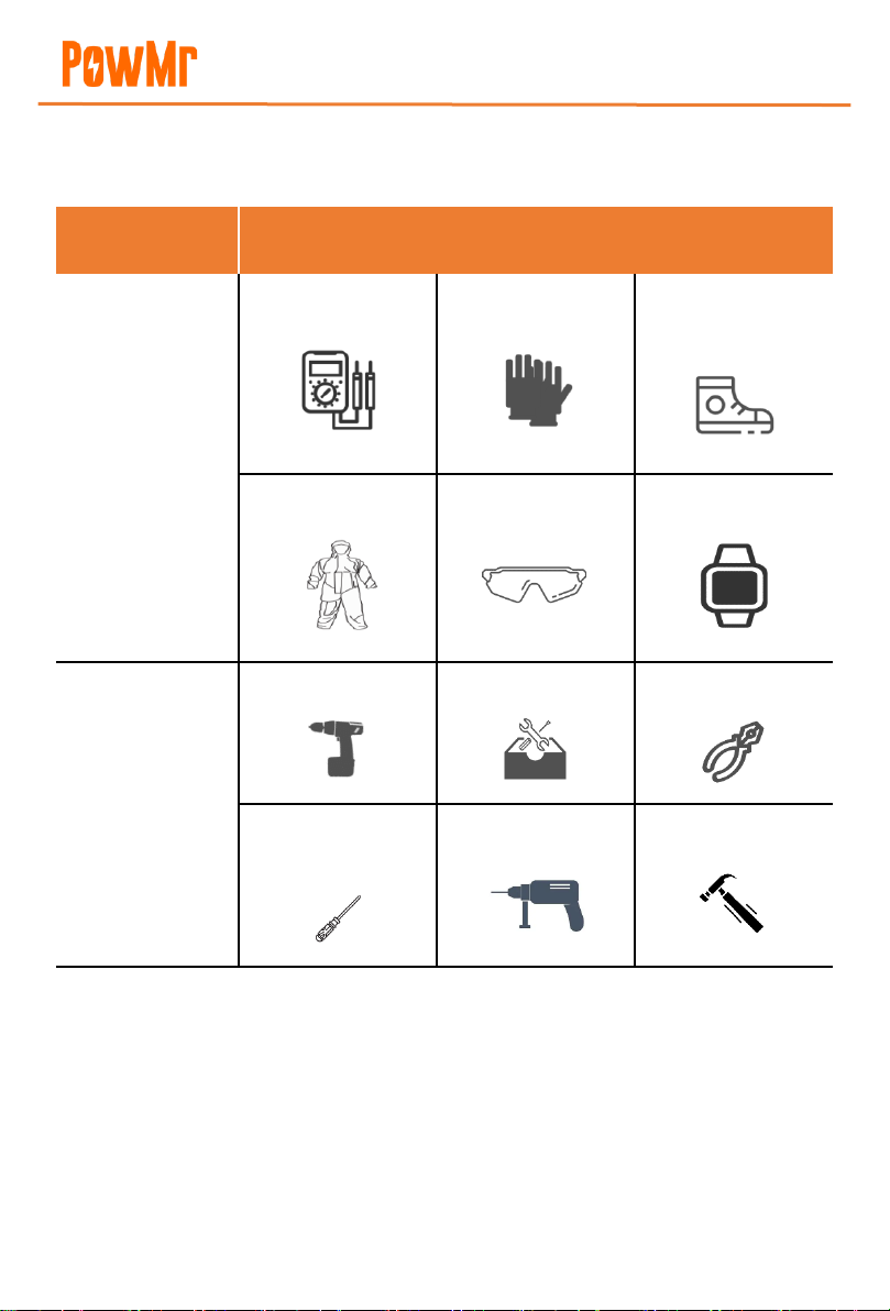
3.2 Installation Tools.................................................................................................................................. 3
3.3 Precautions........................................................................................................................................... 4
4Overview of Main Components...................................................................................................................6
5Product Introduction...................................................................................................................................... 7
5.1 Overview................................................................................................................................................ 7
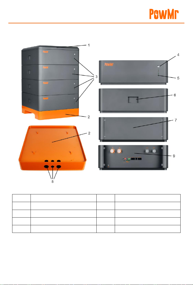
5.2 Product Appearance........................................................................................................................... 8
5.3 Battery Port Panel...............................................................................................................................9
6Battery Installation and Wiring .................................................................................................................11
6.1 Battery Installation ...........................................................................................................................11
7Debugging ......................................................................................................................................................13
7.1 Battery Communication Pin Definitions......................................................................................13
7.2 RS232 Upper Computer Communication...................................................................................14
7.3 ADS DIP Switch Definitions ............................................................................................................14
7.4 Battery Parallel Connection DIP Switch Diagram .....................................................................16
7.5 Power-On Sequence ........................................................................................................................18
7.6 Common Issues and Solutions ......................................................................................................18
7.7 Inverter Matching Information ......................................................................................................20
8Technical Specifications...............................................................................................................................22
9Precautions .....................................................................................................................................................23

User Manual
POW-LIO51 Series
1
1Overview
1.1 Scope
This user manual provides information, operating instructions, and maintenance guidelines for the
POW-LIO51400-16S low-voltage residential energy storage battery series. The POW-LIO51
residential energy storage series is a lithium battery system developed by PowMr, designed to be
compatible with various inverter brands available in the market.
1.2 Intended Audience
This manual is intended for professional technical personnel involved in the installation, operation,
and maintenance of lithium batteries, as well as end-users seeking technical information.
1.3 Manual Usage
1. Before using the product, carefully review this user manual and keep it in a readily accessible
location.
2. All information in this user manual, including images and symbols, is proprietary to PowMr.
Unauthorized use of any part or all of the content is strictly prohibited for individuals outside
the company.
3. Considering the potential for updates and corrections to the manual content, users are advised
to use the provided documentation as a reference. For the latest user manual, please refer to
the product documentation provided or contact customer service through the official website.

User Manual
POW-LIO51 Series
2
2Product Introduction
2.1 Introduction
1. The POW-LIO51 residential energy storage series is a battery module developed by PowMr
Energy designed for low-voltage lithium battery systems, primarily applied in the home energy
storage sector. It achieves high-precision multi-cell voltage and temperature acquisition.
2. The module employs passive balancing, with a maximum balancing current of 300mA,
enhancing the overall lifespan of the battery pack.
3. The communication interfaces include CAN, RS485, and dry contact communication methods,
enabling parallel communication for up to 16 batteries.
4. Featuring an embedded BMS system, it effectively monitors battery over-temperature, over-
voltage, over-current, and other conditions, reducing the risk of battery damage or even fire,
thereby ensuring personal and property safety.
5. This manual covers the types, sizes, performance, technical characteristics, warnings, and
precautions of the lithium battery system. This specification is applicable exclusively to the
battery systems provided by PowMr Energy.
3Safety Instructions
3.1 Labeling Explanation
To ensure user safety during product use, relevant labeling information with appropriate symbols
is provided in this manual. The following lists symbols that may be used in this manual, so please
read carefully.
Icon
Description
Signifies a low-level potential hazard. Failure to avoid may result in minor or
moderate injury to personnel.
Indicates the presence of high voltage inside the battery module. Touching may
lead to electric shock hazards.
This is the ground protection port (PE). It should be securely grounded to
ensure the safety of operating personnel.

User Manual
POW-LIO51 Series
3
3.2 Installation Tools
Prior to installation, prepare the following tools:
Category
Tools
General Tools
Multimeter
Protective gloves
Insulated safety
shoes
Protective clothing
Safety goggles
Antistatic wrist strap
Installation Tools
Electric screwdriver
Socket wrench
Wire stripper
Phillips screwdriver
(M4/M6)
Electric drill
Hammer

User Manual
POW-LIO51 Series
4
3.3 Precautions
3.3.1 Manual Storage
1. This manual covers crucial information for the POW-LIO51 Home Energy Storage Series. Prior
to operating the product, carefully read this manual as it provides essential assistance in
acquainting you with the product.
2. Store this manual securely for the convenience of relevant installation and maintenance
personnel to refer to during operations.
3. Strictly follow the descriptions in this manual when operating the PowMr Home Energy Storage
Series to avoid equipment damage, injuries, property loss, and other potential issues.
3.3.2 Label Protection
1. Warning labels on the POW-LIO51 Home Energy Storage Series contain crucial safety
operation information. It is strictly prohibited to intentionally tear or damage them!
2. The product has a nameplate on the casing, providing essential parameter information. It is
strictly prohibited to intentionally tear or damage it!
3.3.3 Safety Warning Labels
When conducting installation, routine maintenance, inspections, etc., on the POW-LIO51 Home
Energy Storage Series, to prevent unauthorized individuals from approaching, engaging in
improper operations, or accidents, adhere to the following conventions:
1. Erect clear signage at the switch locations of the PowMr products to prevent accidents caused
by accidental closing.
2. Set warning signs or establish safety warning tape near the operating area to prevent unrelated
personnel from approaching.
3. After maintenance or inspection, conduct a thorough on-site safety check.
3.3.4 Personnel Requirements
1. Only personnel with relevant professional qualifications are allowed to perform various
operations on this product.
2. Operating personnel should be thoroughly familiar with the composition and working
principles of the entire POW-LIO51 Home Energy Storage Series system.
3. Operating personnel should be fully acquainted with the "User Manual" for this product.

User Manual
POW-LIO51 Series
5
3.3.5 Power-On Measurement
After the energy storage battery is installed, there is a high voltage present, and accidental contact
with the positive and negative terminals may result in electric shock injuries. Therefore, when
conducting power-on measurements, attention should be paid to the following:
1. Take necessary insulation protection measures (such as wearing insulated gloves).
2. Accompanying personnel must be present to ensure personal safety.
3.3.6 Measuring Instruments
When performing electrical connections and trial operations on the energy storage backup battery,
and to ensure that electrical parameters meet requirements, relevant electrical measuring
equipment such as multimeters, power meters, etc., should be used. Note the following:
1. Use measuring equipment with a suitable range that conforms to on-site working conditions.
2. Ensure the correct and standardized electrical connections of the instruments to avoid dangers
such as electric arcs.
3.3.7 Maintenance and Inspection
When both the energy storage battery and the inverter are turned off, and electrical connections
are confirmed to be disconnected, maintenance or inspection operations can be carried out on
the energy storage battery cabinet. Pay attention to the following:
1. Ensure that the energy storage battery will not be accidentally re-energized.
2. Use a multimeter to ensure that the energy storage battery is completely de-energized.
3. For parts near potentially live components during operations, use insulating materials for
insulation covering or grounding.
4. It is strictly prohibited to perform maintenance or inspection operations on live equipment!
When performing maintenance or inspection on equipment, it must be ensured that at least
two personnel are present at the site. Maintenance operations can only be carried out after the
equipment is safely de-energized, fully charged, or discharged.

User Manual
POW-LIO51 Series
6
4Overview of Main Components
No.
Image
Name
Quantity
1
Battery
4
2
Top Cover
1
3
Base
1
4
Rad-Positive Power Line
Black-negative Power Line
8
5
Communication Cable
4
8
Product User Manual
1
User
Manual

User Manual
POW-LIO51 Series
7
5Product Introduction
5.1 Overview
The POW-LIO household energy storage series lithium battery module integrates PowMr's high-
capacity, high-safety lithium iron phosphate battery cells. It adopts a stacked design with
advantages in footprint and vertical space utilization. The module incorporates a high-precision
Battery Management System (BMS) unit, monitoring and collecting real-time data on voltage and
temperature inside the module. This enables intelligent temperature control at the cell level and
smart cell balancing, enhancing system efficiency and battery cycle life. The module features a
shock-resistant structure within a cold-rolled sheet metal shell for high safety and reliability,
meeting household standards. Additionally, the module is designed for high stability and
disturbance resistance, ensuring the safe and reliable operation of the battery system.

User Manual
POW-LIO51 Series
8
5.2 Product Appearance
1
Top Cover
6
Handle
2
Base
7
Rear Panel
3
Battery
8
Output Port
4
Low Voltage Switch
9
Back Port Panel
5
Battery Capacity Indicator Light

User Manual
POW-LIO51 Series
9
5.3 Battery Port Panel
No.
Name
Function
Notes
1
Positive Terminal Port
(+)
Battery Positive Output
2
Ground Terminal Port
Battery Ground
3
Reset Button (RST)
Battery Reset
Briefly tap and release within 1-
3 seconds.
4
Operation Light
(RUN)
Battery Operation
Indicator Light
5
Alarm Light (ALM)
Battery Alarm Indicator
Light
6
Capacity Light
(CAPACITY)
Battery Capacity
Indicator Light
7
DIP Switch (ADS)
Define Battery
Communication Code
8
Dry Contact
Dry Contact
Communication
1. Dry Contact 1 - PIN1 to
PIN2: Normally open, closed

User Manual
POW-LIO51 Series
10
during fault protection;
2. Dry Contact 2 - PIN3 to
PIN4: Normally open, closed
during low battery alarm.
9
RS485A
485 Communication
Interface
Communication with inverter
via RS485
10
CAN
CAN Communication
Interface
Communication with inverter
via CAN
11
RS232
1. Monitor batteries and
modify parameters.
2. Perform software
upgrades.
12
RS485B
Communication
between batteries.
Functions are the same, no
distinction between left and
right.
13
Negative Terminal
Port (-)
Battery Negative
Output

User Manual
POW-LIO51 Series
11
6Battery Installation and Wiring
6.1 Battery Installation
Step 1. Prepare tools: Cross-head screwdriver, multimeter, insulated gloves, rack, Ethernet cable,
power cable.
Step 2. Unboxing: Take the battery and other items from the packaging, first check if the battery's
appearance is intact, then verify the completeness of accessories referring to the
accessory list.
Step 3. Assembly: Stack the components in the order of base > battery > top cover.
Step 4. Before connecting in parallel, manually activate the low-voltage switch, use a multimeter
to check if the voltage of each battery is consistent. If consistent, close the battery and
proceed with wiring.
Attention:
⚫The maximum limit for stacking batteries is 4 units. If you need to parallel more than 4
batteries, ensure that each group is stacked with 4 batteries or less.

User Manual
POW-LIO51 Series
12
Step 5. Connect the positive pole (+) of the battery using the positive power cable, and then
connect the negative pole (-) using the negative power cable.
Step 6. Use a communication cable to connect the RS485B communication interface of adjacent
batteries (RS485B battery parallel ports have the same function and are not
distinguished).
Step 7. Ground all batteries by connecting the ground wire. The ground terminal is located at the
bottom left corner of the battery; lock the ground wire terminal in this place.
Step 8. Use a standard Category 6 cable. Connect one end to the RS485A (or CAN)
communication interface of the battery and the other end to the RS485 (or CAN) interface
of the inverter (note that the pin definition of the inverter communication should
correspond to the battery).
Step 9. Connect the negative (-) terminal of the last battery module to the battery negative
terminal interface of the inverter using a power cable through the output port. Next, use
a power cable to connect the positive (+) terminal of the last battery module to the
battery positive terminal interface of the inverter through the output port (after battery
parallel connection, the remaining two positive terminal connection ports have the same
function and are not distinguished; the same applies to the two negative terminal
connection columns).
Step 10.DIP Switch Definition: Define the battery connected to the inverter as 1, indicating the
host. Define other batteries sequentially as 2-15.
Attention:
⚫Define the topmost battery on the rack as the first one, and the bottommost battery as
the last one.
⚫Batteries directly connected to the inverter via communication cables are defined as hosts.
The host's DIP switch is set to 1, and it needs to be switched before powering on.
⚫Define other batteries sequentially from 2 to 15. Do not repeat the setting of DIP switch 1.

User Manual
POW-LIO51 Series
13
7Debugging
7.1 Battery Communication Pin Definitions
1. The interfaces for communication between the battery and the inverter through RS485A
(default baud rate: 9600 bps) are defined as follows:
PIN2/7 (white orange)
485-A
PIN1/8 (orange)
485-B
2. The interfaces for communication between the battery and the inverter through CAN (default
baud rate: 500K) are defined as follows:
PIN4(blue): CANH;PIN5(blue & white): CANL
Note:
⚫The default RS485 protocol for the battery is set to Pylontech RS485 (V3.5) protocol. If
compatibility with other inverters is needed, it is necessary to communicate through RS232
with the host computer to change the default protocol.

User Manual
POW-LIO51 Series
14
7.2 RS232 Upper Computer Communication
Refer to the Upper Computer Software Operation Guide for details.
7.3 ADS DIP Switch Definitions
Address
DIP Switch Position
Illustration
#1
#2
#3
#4
0
OFF
OFF
OFF
OFF
1
ON
OFF
OFF
OFF
2
OFF
ON
OFF
OFF
3
ON
ON
OFF
OFF
4
OFF
OFF
ON
OFF
5
ON
OFF
ON
OFF
6
OFF
ON
ON
OFF
7
ON
ON
ON
OFF
Note:
⚫The battery is factory-set with the default CAN protocol, defaulting to Pylontech CAN
(V1.2) protocol. If compatibility with other inverters is required, it is necessary to
communicate through RS232 with the upper computer to change the default protocol.
Tip:
⚫For battery and inverter communication, choose either RS485 or CAN.

User Manual
POW-LIO51 Series
15
8
OFF
OFF
OFF
ON
9
ON
OFF
OFF
ON
10
OFF
ON
OFF
ON
11
ON
ON
OFF
ON
12
OFF
OFF
ON
ON
13
ON
OFF
ON
ON
14
OFF
ON
ON
ON
15
ON
ON
ON
ON

User Manual
POW-LIO51 Series
16
7.4 Battery Parallel Connection DIP Switch Diagram
1 Battery
2 Battery
3 Battery
4 Battery
5 Battery
6 Battery
7 Battery
8 Battery
9 Battery
10 Battery
11 Battery
12 Battery
13 Battery
14 Battery
15 Battery
16 Battery

User Manual
POW-LIO51 Series
17

User Manual
POW-LIO51 Series
18
7.5 Power-On Sequence
After the completion of the connections between the inverter, battery, and mains power, start each
battery one by one. Then, turn on the inverter. After the battery startup, check if the
communication between the inverter and the battery is normal. If the battery data is successfully
uploaded to the inverter, it indicates successful communication between the inverter and the
battery.
7.6 Common Issues and Solutions
No.
Fault Symptoms
Cause Analysis
Solution
1
No DC Output
Battery Voltage Too Low,
Protection Activated
Startup after Charging
Activation
2
Short Power Supply
Time
Insufficient Battery
Capacity or Failure to
Reach Full Charge
Confirm Maintenance or
Replace Battery
3
Battery Cannot
Reach Full Charge
DC Voltage Output from
Power System Lower than
Minimum Charging
Voltage
Adjust Device's DC Output
Voltage to Suitable Charging
Voltage for Battery
4
Unstable Battery
Output Voltage with
Significant
Fluctuations
Interference with
Management System
Operation
Restart the System
5
Temperature
Monitoring Too Low
Damage to Temperature-
Sensing Crystal Head
Replace the Collection Line
with a Temperature-Sensing
Crystal Head
6
Unable to Charge
Single Cell Protection
Activated upon Full
Battery Charge
Discharge Protection Removal
7
Unable to Charge
and Discharge
Short Interval between
Battery and Inverter
Remove Inverter, Reconnect
According to the Specified
Other manuals for POW-LIO51 Series
1
This manual suits for next models
1
Table of contents
Other PowMr Batteries Pack manuals