manuals.online logo
Brands
  1. Home
  2. •
  3. Brands
  4. •
  5. Panasonic
  6. •
  7. Fan
  8. •
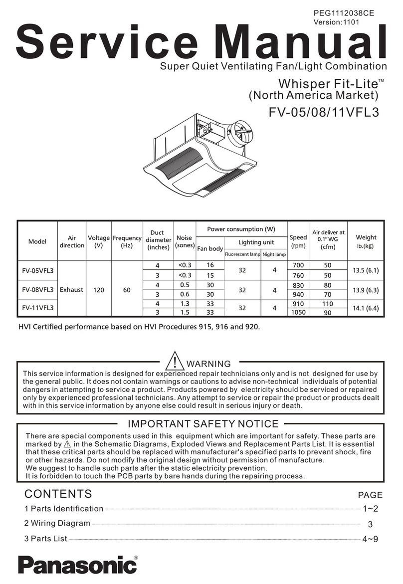
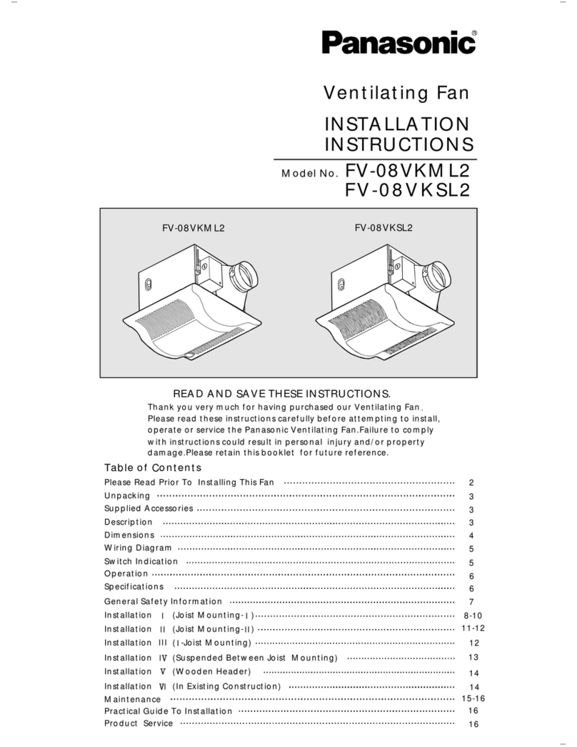
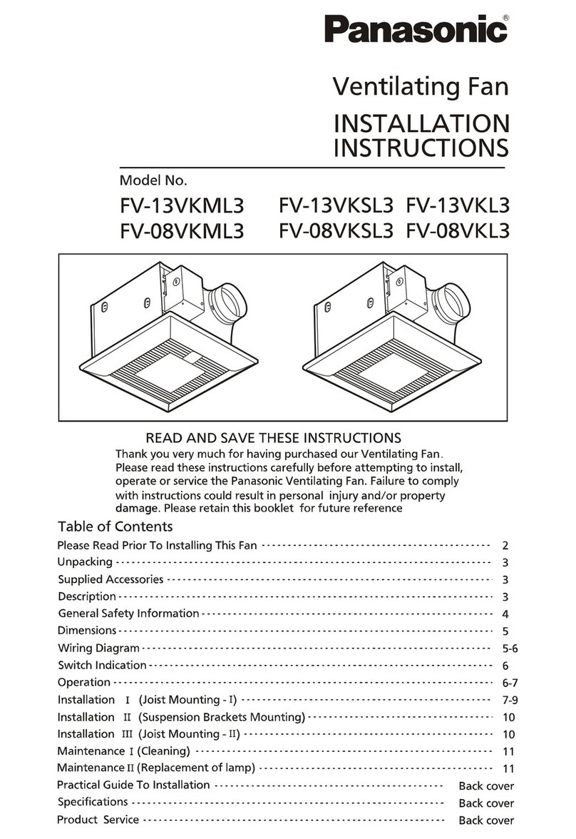
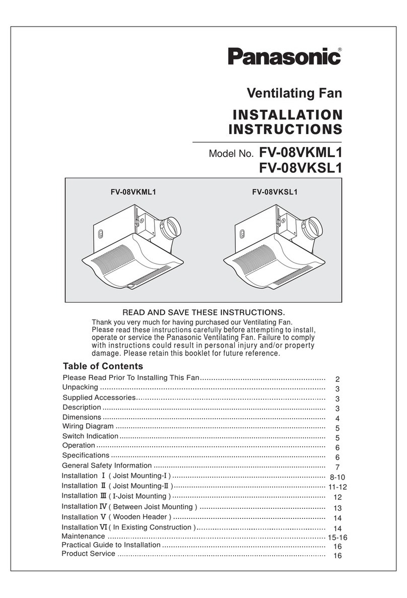
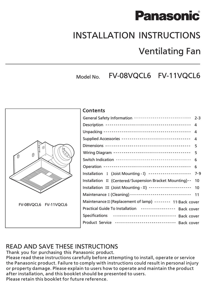
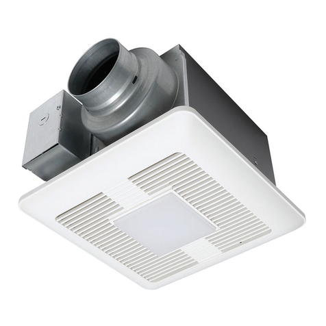
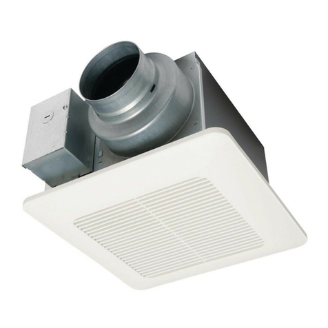
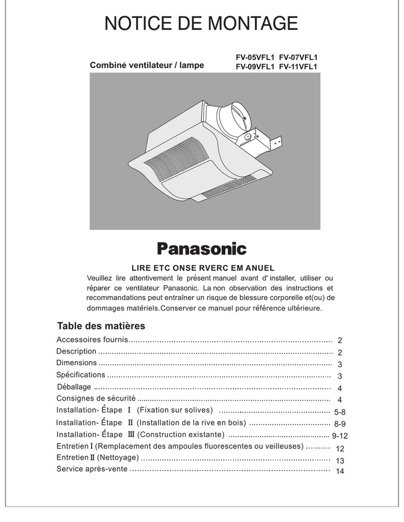
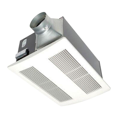
  9. Panasonic FV-05VFL1 User manual

Panasonic FV-05VFL1 User manual

II
I
III
II
I
READ AND SAVE THESE INSTRUCTIOINS.
Specifications
Dimensions
Description
INSTALLATION
INSTRUCTIONS
9-12
FV-05VFL1
FV-09VFL1
FV-07VFL1
FV-11VFL1
Ventilating Fan/
Light Combination
Maintenance (Replacement of Fluorescent Lamp or Night Lamp)
Maintenance (Cleaning)
Pro uct Service
12
13
14
8-9
5-8
4
4
3
3
2
2
Please rea these instructions carefully
before
attempting to install,
operate or service the Panasonic Ventilating Fan. Failure to comply
with instructions coul result in personal injury an /or property
amage. Please retain this booklet for future reference.
Table of Contents
Supplie Accessories
Unpacking
General Safety Information
Installation
( Joist Mounting )
Installation
( Woo en Hea er )
Installation
( In Existing Construction )
DESCRIPTI N
2
1
1
1
1
1
1
1
1
1
connector
Long screws
Clamp
Quantity
Appearance
Part name
Grille
Quantity
Appearance
Part name
2
FV-05VFL1 FV-07VFL1
FV-09VFL1 FV-11VFL1
(M4x30)
(M4x8)
The light unit is an energy-saving, lighting evice which uses two 13W fluorescent lamps an pro uces almost the
same illumination as a stan ar 100W incan escent lamp.
Lamp cover
Light unit
13W
Fluorescent
lamp
4W
Incan escent
lamp
Light kit
set plate
(M4x16)
2
2
8
1
(M4x6)
plate
Short screws I
Short screw II
Short screws III
2
8
Suspension
bracket I
Suspension
bracket II
Suspension
bracket III
Thumb screw
3 inch a aptor
These Panasonic ceiling mount ventilating fan mo els use a low noise sirocco fan riven by a capacitor motor.
The motor is esigne to have an exten e service life with re uce energy consumption.
It also incorporates a thermal-cutoff for safety. The grille covering the main bo y is a spring-loa e ,quick-remove
type. A amper for preventing couterflow is provi e .
SUPPLIED ACCESS RIES
79.2 (3 1/8)
177.4 (7)
265~385 (10 13/32~15 5/32)
3
DIMENSI NS
12
148 (5 13/16)
Unit: mm(inches)
No.
No.
120 60
Hz
V
Mo el No. Air irection
Exhaust
Air eliver at
0.1" WG(CFM)
Bracket cover
Suspension plate
Part namePart name
Grille
Thumb screw
Bo y
Damper
A aptor
Junction box
Night lamp connector
13
Light unit
15
Lamp cover
17
Light kit set plate
19
14
16
18
13W lamp connector
Fluorescent lamp (13W x 2)
Night lamp (4W x 1)
Motor connector
3 inch a aptor connector
FV-05VFL1 FV-07VFL1
FV-09VFL1 FV-11VFL1
FV-05VFL1
FV-07VFL1
FV-09VFL1
FV-11VFL1
Duct
iameter
(inch)
3
4
3
4
3
4
3
4
Power consumption (w) Spee
(RPM)
Fan unit Light unit
Fluorescent lamp Night lamp
15
19
18
16
8
9
4
7
2
10
330 (13 )
73 (2 7/8)
13
20
20
Suspension bracket anII III
Noise
(sone)
14.1
14.1
19.3
19.5
22.8
23.8
26
26
26
26
26
26
4
4
4
4
4
4
0.6
0.4
1.2
0.9
1.5
1.5
50
50
60
70
70
90
921
822
1059
908
1175
1018
Specification are base on HV stan ar .
I
Junction box cover
Suspension bracket I
12
11
Weight
Ib. (Kg)
1
2
3
4
5
6
7
8
9
10
(411/32)
110
84 (3 5/16)
255.6 (10 1 / 16 )
11
14
17
5
6
3
56.7 (2 1/4) 45 (1 25/32 )
139 ( 5 15 / 32 )
1
SPECIFICATI NS
105(4 1/8)
300.6(1
127/32)
252.6 (9 15/16 )
94 (3 23/32)
73 (2 7/8)
4
45
o
UNPACKING
Fig. B
Floor
equipment
Do not install above or
WARNING:
CAUTI N:
Fig. A
A aptor
Refer to the Supplie Accessories list to verify that all parts are present.
Unpack an carefully remove unit from carton.
1. Do not install this ventilating fan where air temperature may excee 40 C (104 F).
oo
2. Make certain that the electric service supply voltage is 120V, 60 Hz.
3. Follow all local electrical an safety co es, as well as the National Electrical Co e (NEC) an
the Occupation Safety an Health Act (OSHA).
4. Always isconnect the power source before working on or near the fan, motor or junction box.
5. Protect the power cor from sharp e ges, oil, grease, hot surfaces, chemicals or other objects.
6. Do not kink the power cor .
7. Do not install the unit where ucts are configure as shown in Fig. A.
8. Provi e suction parts with proper ventilation.
9. This unit is approve for use over a bathtub or shower when installe in a GFCI protecte
branch circuit.
1. For general ventilating use only. Do not use to exhaust
hazar ous or explosive materials an vapors.
2. Not for use in cooking area. (Fig .B)
3. This pro uct must be properly groun e .
To re uce the risk of fire, electric shock or injury to persons, observe the following;
A. Use this unit only in the manner inten e by the manufacturer. If you have any questions, contact the manufacturer.
B. Installation work an electrical wiring must be one by qualifie person(s) in accor ance with all applicable
co es an stan ar s, inclu ing fire-rate construction.
C. Sufficient air is nee e for proper combustion an exhausting of gases through the flue (chimney) of fuel burning
equipment to prevent back rafting. Follow the heating equipment manufacture's gui eline an safety stan ar s
such as those publishe by the National Fire Protection Association (NFPA), an the American Society for Heating
Refrigeration an Air Con itioning Engineers (ASHRAE) an the local co e authorities.
D. When cutting or rilling into wall or ceiling, o not amage electrical wiring an other hi en utilities.
E. Ducte fans must always be vente to the out oors.
F. These mo els are UL liste for tub an shower enclosures.
G. Soli state controls may cause harmonic istortion which can cause motor humming noise.
H. Before servicing or cleaning unit, switch power off at service panel an lock the service isconnecting
means to prevent power from being switche on acci entally. When the service isconnecting means
cannot be locke , securely fasten a prominent warning evice, shch as a tag, to the service panel.
I. NEVER place a switch where it can be reache from a tub or shower.
J. Not to be installe in a ceiling thermally insulate to a value greater than R40.
(Cooking area)
insi e this area
Cooking
GENERAL SAFETY INFORMATION
45
o
Lea wires
Green wires
Wire nut
Junction box
Con uit
Duct
Fig. 2
Junction box cover
Ceiling joist
Long screw
A aptor
Ceiling joist
Fig. 1
Damper
Remove
tape
4Inch
A aptor
Connection metho for 3 inch a aptor connector
5. Install circular uct (4 inch) or 3 inch a aptor connector
an secure it with uct tape. (Fig.3.1, Fig.3.2)
CAUTI N:
Wiring diagram
Joist spacing A shoul be between 380mm (14 31/32inch) an
265mm(10 7/16 inch).
Keep the istance B (21.6mm,7/8 inch) for the thickness of
ceiling boar .
2. Remove a aptor from bo y an secure to ceiling joists
Tape
using long screws (M4x30). Make sure the a aptor is level
an square (perpen icular) with the joists. (Fig.2)
Fan unit
Re
Capacitor
White
Motor
Black
Green
Junction box
Night Lamp
Ballast Lamp Ballast Lamp
Green
Earth groun
Black
White
Power Supply
AC 120V 60Hz
Power Supply
AC 120V 60Hz
Light unit
Fig.3.2
Fig.3.1
B
A aptor Tape Duct
INSTALLATION (JOIST MOUNTING)I
1. Disconnect plug connector from receptacle before
starting installation.
IMP RTANT:
Remove the tape from amper an a aptor before
installation. As shown in Fig.1.
CAUTI N:
3. Remove junction box cover an secure con uit to junction box
knock- out hole. (Fig.3)
4. Refer to wiring iagram below.
Using wire nuts, connect house power wires to ventilating fan
wires: black to black; white to white;green to green.
Replace the junction box cover.
Mount junction box cover carefully so that lea wires are not
pinche .
3 inch a aptor connector
Suspension
bracket I
5
Fig. 7
Fan
Plug connector
Thumb screw
Ceiling joist
Fan bo y
mm (inches)
A aptor
Screw
Screw river
Ceiling joist
Fan bo y
Ceiling joist
Fan bo y
of page 5.
1.Loosen 4 screws (but o
not remove them from
blower).(Fig.5-1)
When mounting
body and blower
separately
8. Secure fan bo y to a aptor using two thumb screws.(Fig.7)
9. Connect plug connector to receptacle .(Fig.8)II
Make sure that bo y "Claws" are property inserte into a aptor
slots.
IMP RTANT:
6. Remove ceiling section. (Fig.4)
7. Insert fan bo y into ceiling. (Fig.6)
6
Receptacle
(for fan)
I
I
A apter
Receptacle
(for night lamp)
Ii
Receptacle
(for 13W lamp)
IiI
Tape
Tape
10.Connect plug connector
to receptacle . (Fig.8)II
Tape
Tape
290 (11 1/ 2)
290 (11 1/ 2)
INSTALLATION (JOIST MOUNTING) CONTINUEDI
2. Remove blower section.
(Fig.5-2)
3.Remove a aptor from
fan bo y an secure to
ceiling joists as in Fig.2
4.Insert fan bo y (without
blower section) into
ceiling.(Fig.6)
5.Secure the a aptor an
fan bo y using one thumb
screw as shown in Fig.5-3.
6.Secure the fan bo y to
the ceiling joists as shown
in Fig.9 an Fig.10 of
page 7.
7.Insert the blower into the
fan bo y. (Fig.5-4)
8.Secure the blower by 4
screws as shown in
Fig.5-5.
9.Mount the fan bo y with
thumb screw (on the right
si e of bottom of the
a aptor) as shown in
Fig.7.
Screw
Fig. 5-1
Blower
Fan bo y
Fig. 5-2
Fig. 5-3
Fig. 5-4
Fig. 5-5
Ceiling
Ceiling joist
A aptor slots
Claws
Fig.4
Fig. 6
Fig. 8
Ceiling joist
Ceiling joist
Suspension bracket II
Suspension bracket III
Ceiling joist
Suspension bracket II
4-Long screws Suspension bracket III
4W Night Lamp
Fluorescent lamp
Light unit
10. Secure fan bo y to ceiling joists using long screws (M4X30) in
11. Secure suspension bracket an to the fan bo y using 2
short screws (M4x6). (Fig.10)
12. Fix the light kit set plate to the frame using 4 short screws
(M4x6). (Fig.11)
II III
I
III
II
13. Insert the plug connector an plug connector into the
receptacle an receptacle respectively, an attach the
light unit to the fan unit with 2 short screws (M4x16) an 1
short screw (M4x8). (Fig.12)
14. Insert the fluorescent lamps an screw the night lamp into the
light unit. (Fig.12)
II III
Ii III
I
II
horizontal irection with suspension bracket an . (Fig. 9)II III
Short screws I
7
Fig. 12
Short screws II
Short
screws III
Fig. 11
Receptacles
Light kit set plate Short
screws III
Short
screws III
Plug connector
Plug connector
Receptacle III Receptacle II
Plug connector III
Plug connector II
Fig.9
2-screws
Fig. 10
INSTALLATION I(JOIST MOUNTING) CONTINUED
Fan bo y
Thumb screws
Mounting spring
Light unit
Lamp Cover
Fig. 13
8
1. Before installation, secure a aptor to fan bo y using two
thumb screws. (Fig.14)
Fig. 14
Fig. 16
15. Insert the lamp cover to the grille an attach the grille to the
fan unit. (Fig.13)
3. Insert the plug connector an plug connector into the
receptacle an receptacle respectively, an attach the
light unit to the fan unit with 2 short screws (M4x16) an 1
short screw (M4 x 8). Insert the fluorescent lamps an
screw the night lamp into the light unit. (Fig.12, Fig.16)
II III
II III
I
II
2. Fix the light kit set plate to the frame using 4 short screws
(M4x6). (Fig.15)
III
Short
screws I
Short
screw II
Light unit
Fig. 15
Light kit set plate
Short
screws III
Short
screws III
Junction
box
Slot
Grille
Grille
INSTALLATI N (J IST M UNTING) C NTINUEDI
INSTALLATI N (W DEN HEADER)II
CAUTI N:
To install the ventilating fan, follow the proce ures escribe in lnstallation II. Take the following precautions before
installation.
Long screws
Junction box cover
mm (inches)
Ventilating fan
A aptor
Ceiling joist
Hea er
Ceiling joist
Wiring diagram
CAUTI N:
A aptor
Fan unit
Re
Capacitor
White
Motor
Black
Green
Junction box
Night Lamp
Ballast Lamp Ballast Lamp
Green
Earth groun
Black
White
Power Supply
AC 120V 60Hz
Power Supply
AC 120V 60Hz
Light unit
,
INSTALLATI N (W DEN HEADER) C NTINUEDII
4. Install hea er between ceiling joists using nails or screws. (Fig.17)
5. Install the ventilating fan an secure with screws. (Fig.17 an Fig.18)
6. Insert the circular uct to the a aptor an secure with uct tape.
Remove the junction box cover an secure con uit to junction
box knockout hole (7/8 inch) (Fig.18)
7. Refer to wiring iagram.
Using wire nuts, connect house power wires to ventilating fan wires:
black to black; white to white; green to green.
Replace the junction box cover.
Mount junction box cover carefully so that lea wires are not
pinche
8. Finish ceiling work. Ceiling hole shoul be aligne with
e ge of the flange. (Fig.19 )
9. Mount grille to fan bo y. (Fig.13, page 8.)
Fig. 17
Circular uct
Fig.18
Ceiling
Flange
Fig.19
1. Installation in existing construction.
Installing the ventilating fan in an existing buil ing requires an accessible area (attic or crawl space) above the planne
installation location or existing ucting an wiring.
Check area above planne installation location to be sure that:
1. Duct work can be installe an that area is sufficient for proper ventilation.
2. Wiring can be run to planne location.
3. No wiring or other obstructions will interfere with installation.
Inspect uct work an wiring before procee ing with installation.
Plan suitable location for ventilating fan.(next to ceiling joist)
9
INSTALLATI N (IN EXISTING C NSTRUCTI N)III
Ceiling joist
Ceiling
Long screws
A aptor
Duct
Junction box cover
Con uit
mm (inches)
Ceiling
Suspension bracket I
Suspension bracket II
CAUTI N:
Fig. 20
Fig. 21
Fig. 22
3 inch a aptor
connector
Duct tape
10
Before installation, provi e inspection an maintenance access at a location that will not interfere with
installation work shown in installation .II
First, remove ceiling section accor ing to Fig.4 of page 6.
Install ventilating fan.
2. Installation from accessible area above fan location.
Inspect uct work an wiring before procee ing with installation.
Remove ceiling section accor ing to Fig.4 of page 6.
Install ventilating fan.
3. Installation without removing ceiling.
Check area above planne installation location to be sure that:
1. Ensure that the square hole size in ceiling shoul be sufficient accor ing to Fig.20
2. Duct work can be installe an that area is sufficient for proper ventilation.
3. Wiring can be run to planne location.
4. No wiring or other obstructions will interfere with installation.
Loosen 4 screws (but o not remove them from blower) as
shown in Fig.5-1 of page 6.
Remove blower from fan bo y as shown in Fig.5-2 of page 6.
an then remove a aptor from fan bo y.
Remove junction box cover an secure the existing con uit
to junction box knockout hole.(Fig21)
Refer to wiring iagram on page 9.
Using wire nuts, connect house power wires to ventilating fan wires:
black to black; white to white; green to green.
Replace the junction box cover.
Secure a aptor to ceiling joists with 4 long screws (M4X30)
insi e of the ceiling as shown in Fig.22.
If the location is in the mi le between 2
joists, connect suspension bracket an
as shown below.
III
Install circular uct(4 inch) or optional part (3 inch a aptor
connector) an secure it with cuct tape as shown in Fig.21.
Ceiling joist
Suspension bracket I
INSTALLATI N (IN EXISTING C NSTRUCTI N) C NTINUEDIII
260(10 1/4)
260(10 1/4)
11
Fan bo y
Fig. 25
Clamp plate
2-square knock-out
Han river
Replace with clamp plates(accessories) an secure the fan
bo y on ceiling boar with 2 short screws III (M4 x 6) from
insi e of the rame. (Fig.25)
Insert fan bo y into ceiling as shown in Fig.24.
Fig. 23
Fig. 24
Insert the blower into the fan bo y. (Fig. 26)
Tape
Tape Short screws III
Fan bo y
Fig. 26
INSTALLATI N (IN EXISTING C NSTRUCTI N) C NTINUEDIII
Remove the 2 square knock-out carefully from surface
of the frame by screw river ( Fig.23) an remove the
bracket cover on the other si e of the frame bo y.
Secure the fan bo y to the a aptor by using one thumb screw
as shown in Fig.5-3 of page 6.
Fan bo y
Ceiling
A apter slots
Claws
Ceiling
Blower
Ceiling
12
13
Mounting spring
Slot
Maintenance (Replacement of fluorescent lamp of night lamp)I
Screw
Connect plug cnnector to receptacle . (Fig.8 of page 6.)II
Secure blower to fan bo y with screws that were loosen before.
(Fig.27)
Fix the light kit set plate to the frame using 4 short screws
(M4x6)
III
as shown in Fig.11 of page 7.
15
Insert the fluorescent lamps an screw the night lamp into
the light unit as shown in Fig.12 of page 7.
17
Insert the lamp cover to the grille an attach the grille to the
fan unit as shown in Fig.13 of page 8.
18
16 Insert the plug connector an plug connector into the receptacle
an receptacle respectively, an attach the light unit to the fan
unit with 2 short screws (M4x16) an 1 short screw (M4x8) as
shown in Fig.12 of page 7.
II III
II III
III
Mount the fan bo y with thumb screw (on the right si e of
bottom of the a aptor) as shown in Fig.7 of page 6.
Fan bo y
Fig. 27
Fig. 29
(Fig. 29)
(Fig. 30)
Fig. 30
(Fig. 28)
Fig. 28
INSTALLATI N (IN EXISTING C NSTRUCTI N) C NTINUEDIII
Screw river
Ceiling
WARNING:
1. Disconnect power source before working on unit.
2. The lamp's glass is fragile. Please han le with
care. To remove lamp, grasp at base an move
back an forwar to loosen.
Do not pull har on the lamp or you may break the
glass.
3. 4W night lamp has threa e base. Remove by
turning counterclockwise.
1. Remove grille.(Squeeze mounting spring an pull own)
Grille
Gloves
2. Disconnect the connector II or connector of light
unit.
III
3. Change the fluorescent bulbs (Panasonic FDS 13E
27. U/2, 13W or FQ13E 41.U/ 2, 13W or FQ13E 35.U/ 2,
13W) or the 4W incan escentlamp, connect the connector
or connector an replace the grille.II III
12
14
13
Maintenance (Cleaning)II
Vacuum cleaner
Mounting spring
Slot
(Fig. 32)
Fig. 31
(Fig. 33)
Fig. 33
Fig. 32
Fig. 34
(Fig. 31)
(Fig. 12 on page 7 and Fig.13 on page 8)
WARNING:
Disconnect power source before working on unit. Routine maintenance must be one every year.
CAUTI N:
1. Never use gasoline, benzene, thinner or any other similar chemicals for cleaning the grille an the
ventilating fan.
2. Do not allow water to enter motor.
3. Do not expose plastic parts to temperature over 140 F (60 C).
oo
1. Remove grille.(Squeeze mounting spring an pull own)
2. Wash an clean grille. (Use non-abrasive kitchen
etergent)
Grille
Gloves
3. Remove ust an irt from fan bo y using a vacuum
cleaner. (Remove bulbs if necessary.)
4. Using a cloth ampene with kitchen etergent,
remove any irt from fan bo y. Wipe ry with new
cloth.
5. Replace bulbs an grille.
PR DUCT SERVICE
PANAS NIC CANADA INC.
One Panasonic Way, Secaucus, NJ, 07094
PANAS NIC C NSUMER ELECTR NICS C MPANY
www.panasonic.ca
14
5770 Ambler Drive, Mississauga, ON L4W 2T3
The unit shoul be service by qualifie technicians only.No service information is provi e for customers. Your pro uct
is esigne an manufacture to ensure a minimum of maintenance. However, shoul your unit ever require service, a
nationwi e system of factory service centers an AUTHORIZED INDEPENDENT SERVICE CENTER is maintaine to
support your pro uct's warranty.
(In the U.S.A., call 1-886-292 7292 to locate the Panasonic Authorize Service Center nearest you.)

Other manuals for FV-05VFL1

1

This manual suits for next models

3

Other Panasonic Fan manuals

Panasonic FV-11VF2 User manual

Panasonic

Panasonic FV-11VF2 User manual

Panasonic F-M15EC User manual

Panasonic

Panasonic F-M15EC User manual

Panasonic Whisper Fit-Lite FV-11VFL3 User manual

Panasonic

Panasonic Whisper Fit-Lite FV-11VFL3 User manual

Panasonic F-M12GX User manual

Panasonic

Panasonic F-M12GX User manual

Panasonic F-60TAN User manual

Panasonic

Panasonic F-60TAN User manual

Panasonic F-60FEN User manual

Panasonic

Panasonic F-60FEN User manual

Panasonic Whisper Green-Lite FV-08VKL1 User manual

Panasonic

Panasonic Whisper Green-Lite FV-08VKL1 User manual

Panasonic FV-08VS1 User manual

Panasonic

Panasonic FV-08VS1 User manual

Panasonic FV-24JR2 User manual

Panasonic

Panasonic FV-24JR2 User manual

Panasonic FV-15AUL1 User manual

Panasonic

Panasonic FV-15AUL1 User manual

Panasonic F-M14E2 User manual

Panasonic

Panasonic F-M14E2 User manual

Panasonic WhisperCeiling FV-15VQ4 Operation and maintenance manual

Panasonic

Panasonic WhisperCeiling FV-15VQ4 Operation and maintenance manual

Panasonic Whisper Green FV-05VK1 User manual

Panasonic

Panasonic Whisper Green FV-05VK1 User manual

Panasonic WhisperSense FV-08VQCL5 User manual

Panasonic

Panasonic WhisperSense FV-08VQCL5 User manual

Panasonic RG-M79A User manual

Panasonic

Panasonic RG-M79A User manual

Panasonic FV-0511VKS2 User manual

Panasonic

Panasonic FV-0511VKS2 User manual

Panasonic FV-08VRE1 User manual

Panasonic

Panasonic FV-08VRE1 User manual

Panasonic FV-10NLF1 User manual

Panasonic

Panasonic FV-10NLF1 User manual

Panasonic WhisperCeiling FV-20VQ3 User manual

Panasonic

Panasonic WhisperCeiling FV-20VQ3 User manual

Panasonic FV-11VFL2 User manual

Panasonic

Panasonic FV-11VFL2 User manual

Panasonic Whisper Value-Lite FV-10VSL2 User manual

Panasonic

Panasonic Whisper Value-Lite FV-10VSL2 User manual

Panasonic FV-08VRL1 User manual

Panasonic

Panasonic FV-08VRL1 User manual

Panasonic F-56MZG User manual

Panasonic

Panasonic F-56MZG User manual

Panasonic RG-T810LA User manual

Panasonic

Panasonic RG-T810LA User manual

Popular Fan manuals by other brands

Midea FT30-8MB owner's manual

Midea

Midea FT30-8MB owner's manual

Alpha Fan TWF-AC instruction manual

Alpha Fan

Alpha Fan TWF-AC instruction manual

Hunter 28688 Parts guide

Hunter

Hunter 28688 Parts guide

Vornado SSS instruction manual

Vornado

Vornado SSS instruction manual

Home Decorators Collection WALES 56-WALS Use and care guide

Home Decorators Collection

Home Decorators Collection WALES 56-WALS Use and care guide

Daikin FWP-C manual

Daikin

Daikin FWP-C manual

Sinbo SF 6713 instruction manual

Sinbo

Sinbo SF 6713 instruction manual

L.B. White 24D370 owner's manual

L.B. White

L.B. White 24D370 owner's manual

CFM SEF Installation & maintenance instructions

CFM

CFM SEF Installation & maintenance instructions

Caryaire LVLS Installation and maintenance manual

Caryaire

Caryaire LVLS Installation and maintenance manual

Helios SilentBox SB Series Installation and operating instructions

Helios

Helios SilentBox SB Series Installation and operating instructions

Monte Carlo Fan Company 5MMR54 Series owner's manual

Monte Carlo Fan Company

Monte Carlo Fan Company 5MMR54 Series owner's manual

impress iM-783 Use and care book

impress

impress iM-783 Use and care book

Monte Carlo Fan Company 5AHR60 Series owner's manual

Monte Carlo Fan Company

Monte Carlo Fan Company 5AHR60 Series owner's manual

Hunter 23949 Owners and installation manual

Hunter

Hunter 23949 Owners and installation manual

Monte Carlo Fan Company MC263 Series Owner's guide and installation manual

Monte Carlo Fan Company

Monte Carlo Fan Company MC263 Series Owner's guide and installation manual

Monte Carlo Fan Company 3ROZR52 Series Owner's guide and installation manual

Monte Carlo Fan Company

Monte Carlo Fan Company 3ROZR52 Series Owner's guide and installation manual

Exhale Fans EF34 Owner's guide and installation manual

Exhale Fans

Exhale Fans EF34 Owner's guide and installation manual

manuals.online logo
manuals.online logoBrands
  • About & Mission
  • Contact us
  • Privacy Policy
  • Terms and Conditions

Copyright 2025 Manuals.Online. All Rights Reserved.