P+S Technik pro35 Image Converter MKII User manual

Image Converter
Art. Nr. # 22327 Version 0803
Before operating this product, please read the instruction carefully and save this manual for future use.
User Manual
for PRO35 2/3" and PRO35 1/2" Cameras
Model MKII
ENGLISH

3
E
Manufacturer Information:
The manufacturer of this product is
P+S Technik GmbH
Siemensstraße 12
85521 Ottobrunn/Munich
Germany.
Please find worldwide authorised representation and dealer on our homepage
http://www.pstechnik.de or send an e-mail to info@pstechnik.de
asking for the contact details.
Concerning any service and warranty requests, please contact your distributor
or P+S Technik GmbH directly.

4
Safety instructions:
Temperature range:
The Image Converter has been tested for a temperature range from 0°C to +50°C.
For field reports regarding more extreme temperatures please contact P+S Technik
Maintenance / Special Tools:
Do not touch glass components with sharp objects.For cleaning do only use special
lens cleaning supplies. Refer all servicing to qualified service personnel.
Storage:
Please store the Image Converter in a dry and dust free place.
Disposal:
Please dispose broken components and devices correctly.

5
E
Contents:
1. PRO35 Image Converter: ………………………………………………………… 7
1.1 Delivery content ……………………………………………………………………… 7
1.2 Accessories and spare parts ………………………………………………………… 8
1.3 General overview ……………………………………………………………………… 14
2. Setup: ………………………………………………………………………………… 15
2.1 Mounting the Image Converter ……………………………………………………… 15
2.2 Power supply & cabling ……………………………………………………………… 16
2.3 Operating elements of the Image Converter ………………………………………… 17
2.3.1 Start/Stop……………………………………………………………………………… 17
2.3.2 Back focus Adjustment ……………………………………………………………… 18
2.3.3 Target Speed ………………………………………………………………………… 22
2.3.4 Second iris diaphragm ………………………………………………………………… 25
2.4 Adjusting the camera ………………………………………………………………… 27
2.4.1 Shading/Lens Files …………………………………………………………………… 27
3. Tips and General Instructions ………………………………………………… 31
4. Maintenance ………………………………………………………………………… 33
5. Technical Data ……………………………………………………………………… 35
6. FAQ’s…………………………………………………………………………………… 37
7. List of Suitable Lenses for PRO35 …………………………………………… 47
8. Addresses and Contacts ………………………………………………………… 49

6
7
E
PRO35 Image Converter
1
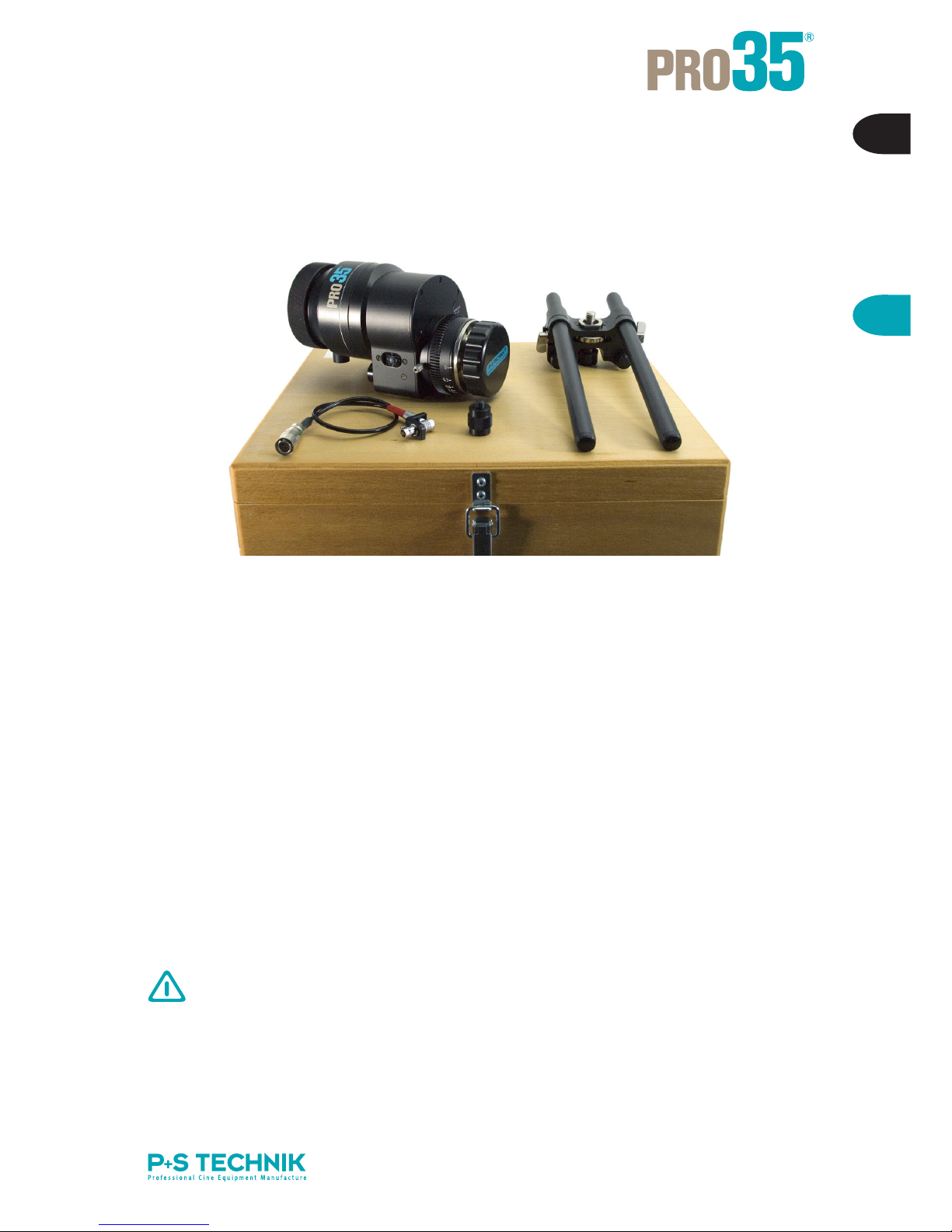
1.1 Delivery Content:
APRO35 Image Converter
Lens Mount: PL Mount (for other Mounts see accessories)
Camera-Mount: 2/3" B4 Mount, 1/3" Bayonet Mount
Lens caps front and back
B15mm Lightweight Support Bridge with
2x 15mm rods 75mm
2x 15mm rods 240mm
C Power cable to lens connector
DAltogether in a wooden box for safe transport
(it is offered an aluminium box as an optimal accessory
The lightweight support bridge for mounting onto the camera
or the quick-lock plate has to be acquired separately.
+++ SEE ALSO LENS SETS FROM P+S TECHNIK http://www.pstechnik.de +++
A
D
C
B

8
1.2 Accessories and Spare Parts:
Art. No. Description
19004 PRO35 PL-Mount Image Converter for 2/3"
B4-Mount camera incl. light weight support (#19186),
power supply cable for lens connector
14000 PRO35 PL-Mount Image Converter for 1/2"
CCD cameras incl. light weight support (#19186),
power supply cable for lens connector
Lens Mounts for PRO35
20737 BNC-R Mount for PRO35
19940 Panavision Mount for PRO35
Professional F Mount for PRO35 (#23504)
19942 Nikon Mount for PRO35
20468 Canon EF-Mount for PRO35
22652 Canon FD-Mount for PRO35
20902 Contax Mount for PRO35
Support accessories by P+S TECHNIK
19376 PRO35 support bridge for 19mm to 19mm rods
19710 PRO35 support bridge for 19mm to 15mm rods
19715 PRO35 support bridge for 15mm to 15mm rods
16251 Pair of rods for bridge plate, 19mm, L=440mm, steel
19545 Pair of rods for bridge plate, 19mm, L=440mm, carbon fiber
18688 Pair of rods for bridge plate, 19mm, L=240mm, steel
19544 Pair of rods for bridge plate, 19mm, L=240mm, carbon fiber

9
E
PRO35 Image Converter
1
Support systems for use with the PRO35 Image Converter
There are four possible solutions, explained in the following:
1. 15mm light weight support (by default delivered with the PRO35)
– for use with normal (prime) lenses
– for attachment of 15mm light weight accessories
2. 15mm light weigth support (ARRI based)
3. 19mm heavy duty support – Chrosziel based
– for use with heavy lenses (i.e. zoom lenses)
– for attachment of 19mm movie accessories
4. 19mm heavy duty support – ARRI based
– for use with heavy lenses (i. e. zoom lenses)
– for attachment of 19mm accessories
Support bridges to adapt from 19mm ligth weigth support to 15mm heavy duty support are
available as well:
Cables and general accessories
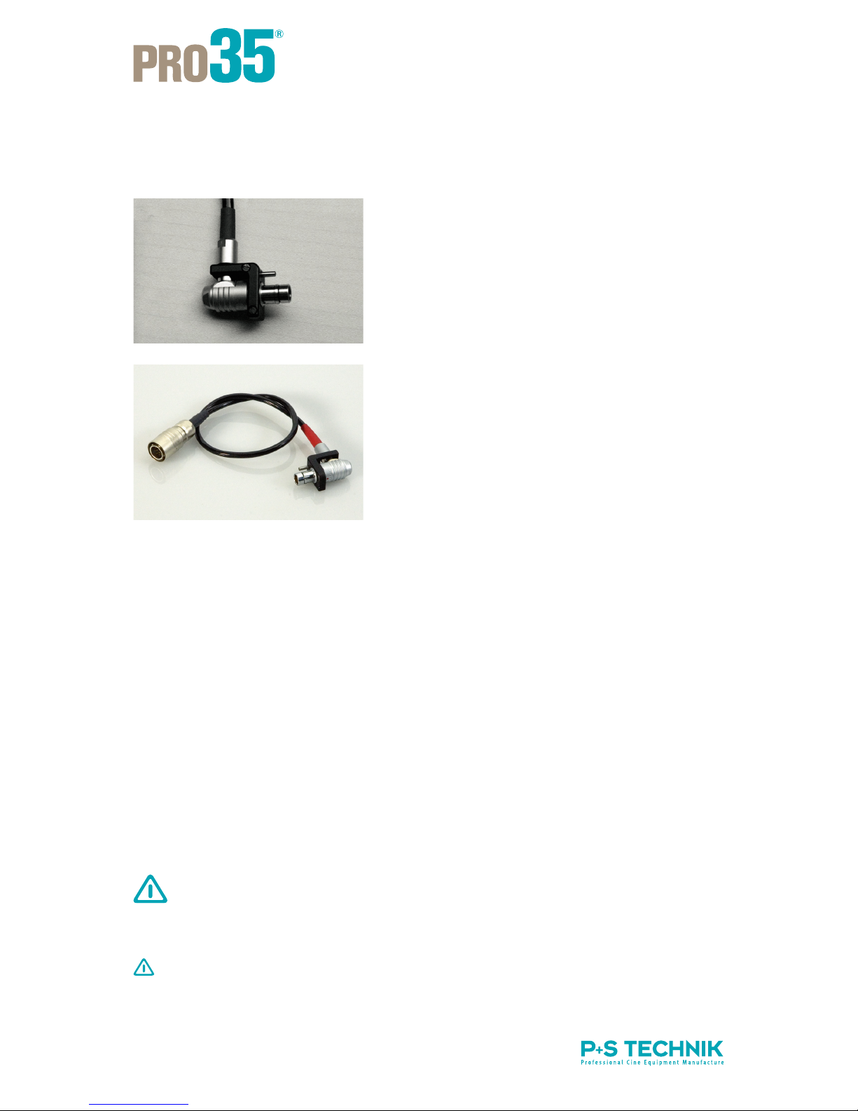
22612 PRO35 power supply cable for “Lens” connector
(Hirose 12-pin/ Fischer 7-pin, angled connector) (with twist protection MK II)
19142 PRO35 power supply cable Anton Bauer 2-pin (with twist protection MKII)
19143 PRO35 power supply cable Digibeta Hirose 4-pin (with twist protection MKII)
19144 PRO35 power supply cable XLR 4-pin (with twist protection MKII)
19187 PRO35 power supply cable XLR 5-pin (with twist protection MKII)
19188 PRO35 power supply cable “open end” (with twist protection MKII)
20449 RS switch ON/OFF (to use with MINI35 and PRO35)
21067 RS switch holder complete (incl. RS switch holder, Cmotion fastener,
RS extension cable 0,8m)
21065 RS extension cable, 0,8m
19710 PRO35 support bridge for 19mm to 15mm rods
19715 PRO35 support bridge for 15mm to 15mm rods

10
1. 15mm Light-weight Support for the PRO35
The 15mm support bridge and rods are included in the delivery. A holder for the 15mm rods
is required on the camera side. This holder is offered by both Chrosziel and ARRI and can be
purchased directly from P+S Technik.
By default the PRO35 Image Converter is delivered with a 15mm light weight support sy-
stem, including a support bridge (3) and four 15mm rods (4). It stabilizes the PRO35 setup
and 15mm accessories can be attached.
IMPORTANT: In order to connect the light weight support to your video camera you need a
holder plate for 15mm rods on camera side, which is prepared for light weight support con-
nection. This holder is possible to purchase directly from P+S Technik.
+++ All products can be ordered by P+S Technik in Munich or through our local dealers +++
Art. No. Description
Holder Plate from ARRI or Chrosziel.
The ARRI light weight support for video cameras is based on the LWS-4.
Light weight supports for Sony, Ikegami, JVC, Hitachi, Philips, Thomson availa-
ble.
Quicklock plate (has to be compatible to your base plate)
Support bridge (comes with the PRO35) (#19004)
Four 15mm rods (come with the PRO35):
75mm (two times) for the support of the Image converter and 240mm (two times)
for additional movie accessories (#19004)
19004 PRO35 Image Converter
11
E
PRO35 Image Converter
1
2. Light Weight Support for the PRO35 Image Converter ( ARRI based )
The following accessories are based on the ARRI LWS-4 and ARRI light-weight adapter
plates for the SONY, PANASONIC and Thomson cameras and allows you to fit additional
accessories, such as follow focus, mattebox....
based on the LWS 15mm support. A special support bridge for the PRO35Digital is inclu-
ded in the delivery of the Image Converter:
Art. No.
19548
19547
21958
19590
16167
19591
Description
Sony Ligth Weigth Adapter SLB-2
Panasonic Ligth Weigth Adapter PLB-2
Ligth Weigth Support LWS-4; compete with 15mm rods
(97mm and 170mm long)
Hand Grip Extension
Hand Grip with ON/OFF Switch
Hand Grip Extension
A
B
C
D
E
F
12
3. 19mm Heavy Duty Support for the PRO35 (Chrosziel based setup)
The following table and drawings describe, which articles are necessary for a Chosziel based
heavy duty support setup in order to use heavy lenses (like zoom lenses) or to connect 19mm
heavy duty based accessories to your PRO35 setup.
Art. No.
18478
18477
19376
16245
16251
19545
18688
19544
Description
Bridge plate for 19mm rods for Sony and Panasonic video cameras
incl. 440mm rods (Chrosziel)
Quicklock plate for Sony and Panasonic video cameras (Chrosziel)
PRO35 support bridge for 19mm rods (without rods)
Pair of spare rods for bridge plate 19mm x 650mm
Pair of spare rods for bridge plate 19mm x 440mm
Pair of spare rods for bridge plate 19mm x 440mm (carbon fibre)
Pair of spare rods for bridge plate 19mm x 240mm
Pair of spare rods for bridge plate 19mm x 240mm (carbon fibre)
+++ All products can be ordered from P+S Technik in Munich or through our local dealers.+++
A
B
C
D

13
E
PRO35 Image Converter
1
4. 19mm Heavy Duty Support for the PRO35 (ARRI based setup)
The following table and drawings describe, which articles are necessary for an ARRI based
heavy duty support setup in order to use heavy lenses (like zoom lenses) or to connect 19mm
heavy duty based accessories to your PRO35 setup.
Art. No.
16198
19570
18047
17995
19376
16245
16251
19545
18688
19544
Description
Bridge plate for S16/N16 cameras (BP-6 compatible) incl. 19mm rods
440mm (or original BP-6 by ARRI)
Sony adapter plate SAP-3 (replaces Sony quick release plate) enabling inter-
face to BP-6 bridge plate
Panasonic adapter plate PAP-2 enabling interface to BP-6 bridge plate
Thomson adapter plate TAP-1 enabling interface to BP-6 bridge plate
PRO35 support bridge for 19mm rods (without rods)
Pair of spare rods for bridge plate 19mm x 650mm
Pair of spare rods for bridge plate 19mm x 440mm
Pair of spare rods for bridge plate 19mm x 440mm (carbon fibre)
Pair of spare rods for bridge plate 19mm x 240mm
Pair of spare rods for bridge plate 19mm x 240mm (carbon fibre)
+++ All products can be ordered from P+S Technik in Munich or through our local dealers +++
14
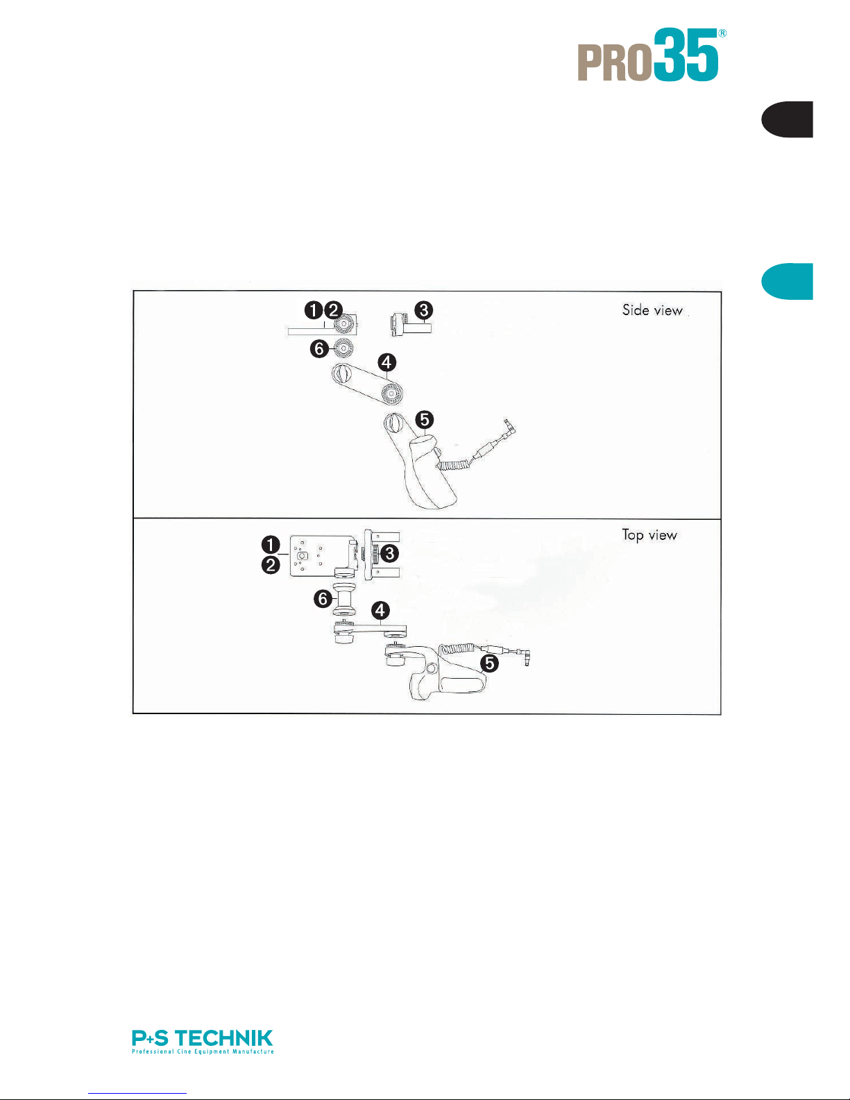
1.3 General Overview:
AINPUT – power connection
BREMOTE connector
CReturn button
DImage Plane
(Line and Tape Hook)
EControl LED:
GREEN – Good speed control
RED – acceptable/low speed
BLINKING – ERROR
(below minimum speed)
FSpeed Control wheel
GManual RUN
Does NOT start the
shooting!
HLever for back focus
IIris diaphragm/ND Function
(adjustable ND Filter)
Bottom 3/8 inch thread for
Light weight support
(15mm Lightweight Support)
3/8 inch thread for bridge plate
support
(19mm Heavy-Duty-Support)

15
E
Setup
2
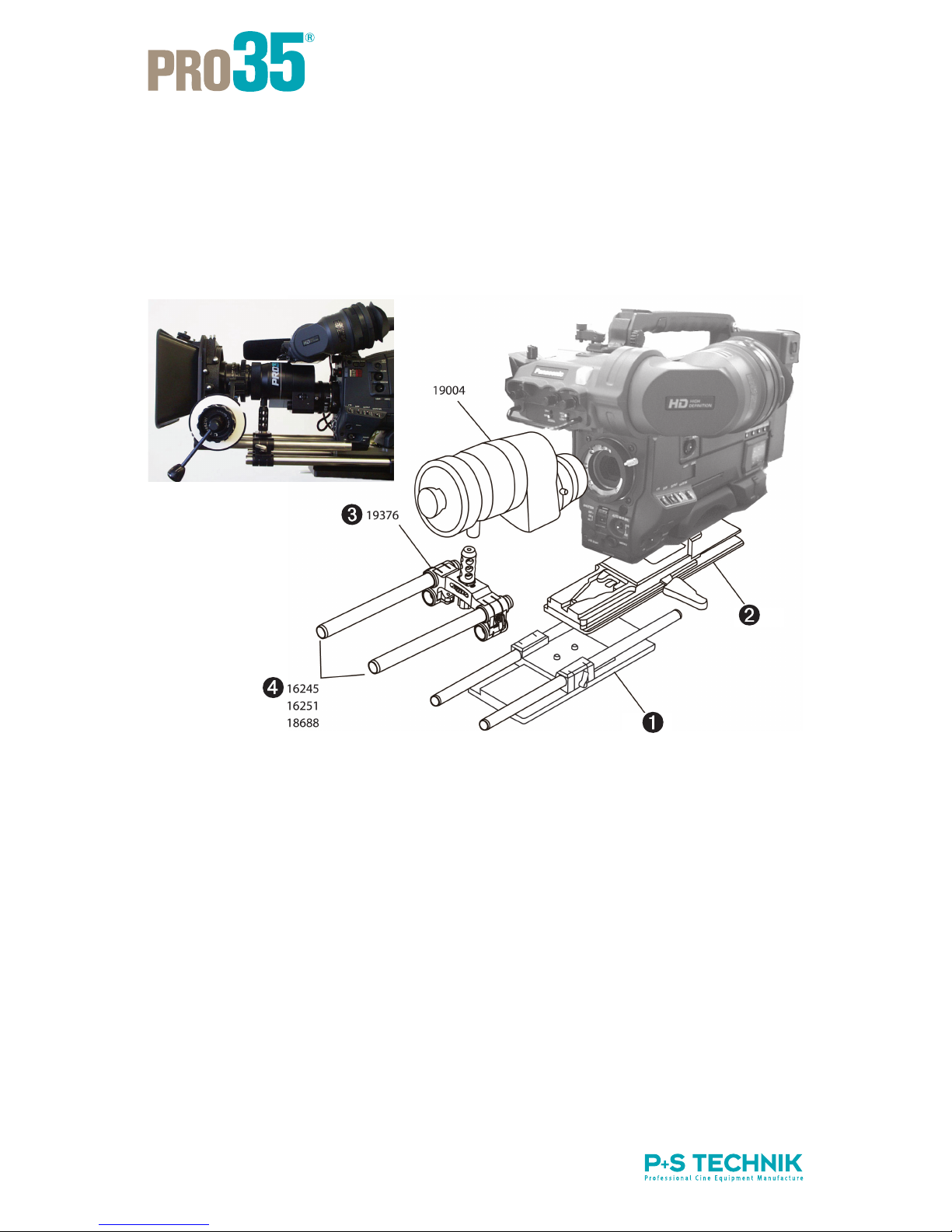
2.1 Mounting the Image Converter:
The following steps explain how to attach the PRO35 properly to your camera:
Instruction Explanatory Notes
1 Make sure that the quick-lock plate holder for the
15mm lightweight support is assembled to the
bottom of the camera as shown in the photo.
2 Assemble the support bridge delivered with the
PRO35 on the quick-lock plate, as shown in the
photo.
3 Assemble the PRO35.
3.1 Attach the post to the bottom of the PRO35
unit.
3.2 Lower the support for easier installation (lever
shown as Screw A in photo).
3.3 Loosen two screws on either side of Screw B in
photo. Like this the bridge can be adjusted if ne-
cessary. For adjusting the bridge loosen screws
on the bottom.
3.4 Install the PRO35 Image Converter on the came-
ra and lock the clamp ring of the B4 Mount.
3.5 Raise Screw A until post bears on precisely.
3.6 Engage and tighten the knob B in the bottom of
the post. Also tighten the two screws placed eit-
her side of Screw B.
16
2.2 Power supply and cabling:
The Fischer-Angle-Plug is equipped with an additional
clamp in order to avoid twisting and the hence result-
ing damage of the connector.
This is a standard for all currently delivered models of
the PRO35. All previous models of the PRO35 can
be upgraded or the twist protection can be removed
easily.
The PRO35 Image Converter can be powered without
any problems.
The unit includes the power cable #22612. From the
lens-connector (Hirose 12 pin) on the camera power
is supplied as well as a Start/Stop signal. This signal
starts and stops the converter automatically (if sup-
ported by the camera manufacturer)
Other power cables are available from P+S Technik,
however without Start/Stop function.
Increased charging rate at low temperature:
The typical consumption of the PRO35 is about 300mA (at a temperature of 20°C). At a
temperature below 0°C the consumption can increase up to 1 Ampere.
If the Image Converter is internally equipped with a locking device, the power supply and con-
trol of the PRO35 Image Converter is typically driven by the 12-pin Hirose (Lens Connector)
of the video camera. Hence a overcharging of the camera is avoided; the Image Converter
shuts down automatically if the power consumption is higher than 1 Ampere.
If the PRO35 is used under conditions, which anticipate high power consumption, the con-
verter can be operated with an external power supply. This could be a direct cable connec-
tion from the camera battery to the PRO35 or the use of a second battery.
In this case the internal power supply can be bridged (switched off). This bridge can be
brazed on the back of the connector plate.
This modification requires experiences in the service of the Image Converter.
Only qualified service technicians are allowed to do these modifications.
MARK MODIFIED SYSTEMS ACORDINGLY IN ORDER TO AVOID DAMAGES ON THE
CAMERA!
P+S Technik give no warranty on modified systems!

17
E
Setup
2
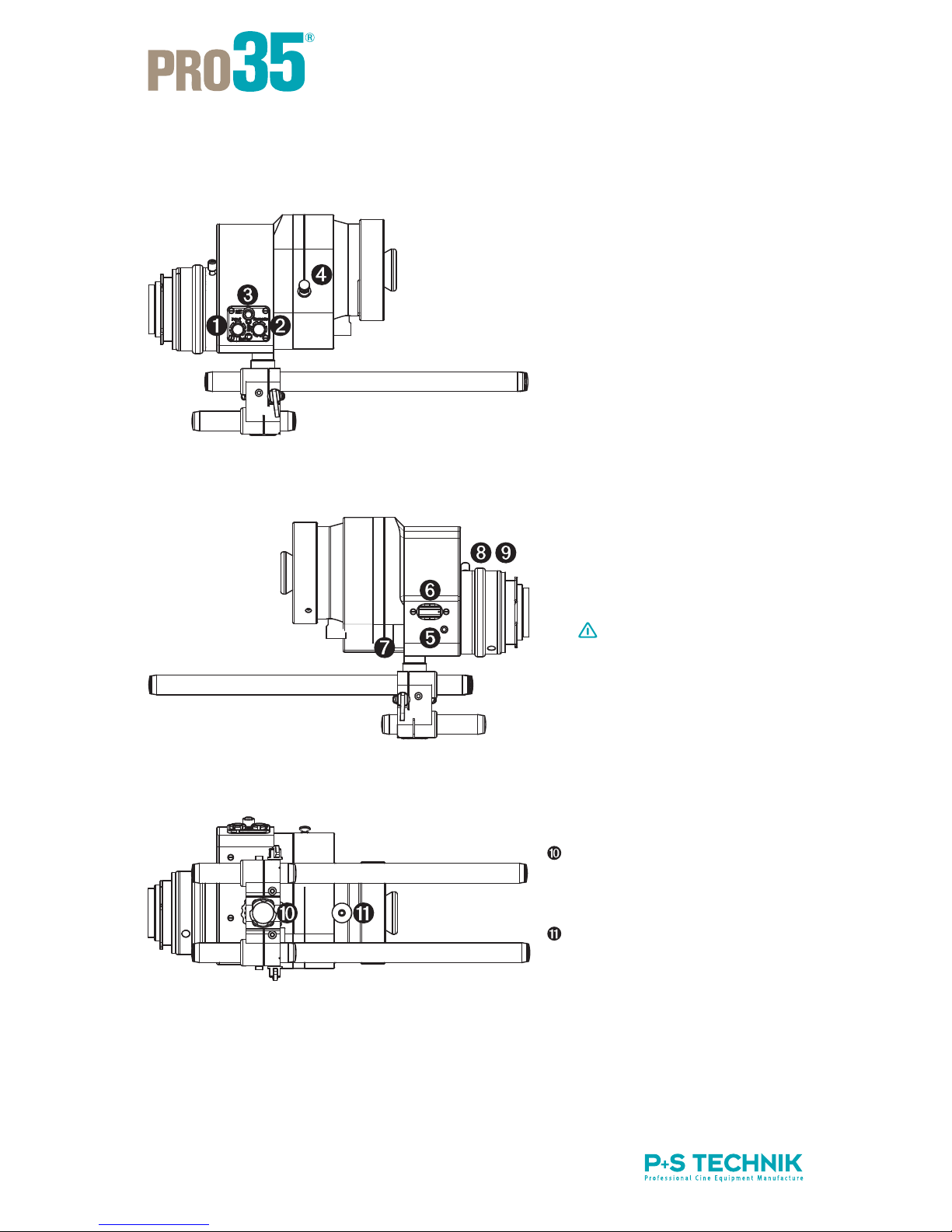
2.3 Operating Elements of the Image
Converter:
2.3.1 Start / Stop:
* While the camera is recording, the RUN-Button gis not active
The Image Converter does NOT start automatically after changing battery
or switching on/off the camera (this is not a failure, but it saves electricity and incre-
ases the lifetime of the mechanical components of the unit).
Check BEFORE shooting, whether the Image Converter:
a) is already running (manual start) or
b) is started automatically with the camera
Manual “RUN” status VTR signal Result
OFF VTR ON*
VTR OFF
Image Converter ON
Image Converter OFF
ON VTR ON*
VTR OFF
Image Converter ON
Image Converter ON
Tip:
Start the shooting AND the Image Converter
SAVELY with an external start/stop switch (e.g.
with the P+S Technik RS switch #20449 or other
compatible switches). Hence you can almost
screen out that the Image Converter is not running
during recording.
The utilization of the RS switch makes a simultane-
ous starting of PRO35 and camera possible.
If the Image Converter has been started manually
(RUN-Button g) a pressure on the VTR-start button
of the camera activates ONLY the recording; the
Image Converter remains in RUN-Mode.

18
2.3.2 Flange focal distance and Back focus:
There are two lens mounts on the PRO35 Image Converter: on the lens side (PL Mount,
Nikon…) and on the camera side (Bayonet Mount). Hence there are two possibilities to ad-
just the flange focal distance:
The lens mount for the film and photo lenses (on the front of the Image Converter); has a
preset flange focal distance, identical to film cameras.
The flange focal distance on the lens mount (front) can be adjusted or collimated with
an inferior flange or on a collimator (see also Service Manual for the PRO35 Image Con-
verter)
The camera side Bayonet Mount of the PRO35 can be adjusted with the back focus
screw:
1.
2.
Different than on film cameras the flange focal dis-
tance is NOT given respectively or is different in
dependency from several factors.
The PRO35 offers naturally the possibility to adjust
the flange focal distance. Therefore it can be used on
every camera with adequate Bayonet Mount.
When is an adjustment of the camera side flange focal distance/ back focus
necessary?
– In case of changing the camera
– In case of variation of temperature +/– 10 °C
– In case of high mechanical load onto the mount of the camera (heavy zoom lens or similar)
– After transportation of the unit respectively other heavy agitation.

19
E
Setup
2
How can the back focus be controlled and adjusted?
1. Adjusting back focus in preparation/test room:
Check if the actually measured distance on the lens leads to a correct visual sharpness.
Beispiel: Place the test chart precise 3m (or another, exact calibrated distance at the lens)
distant from the image plane and adjust the measured distance at the lens. Check the result
on a high-resolution monitor.
1
2
2.1
2.2
2.3
2.4
Instruction
Mount a film lens to the Image Converter.
Place a focus chart at a reasonable distance
and set the focus of the film lens at that
distance.
Turn the Image Converter ON.
Open the adjustable ND FILTER to Position 0.
Close the iris of the film lens to around T4.
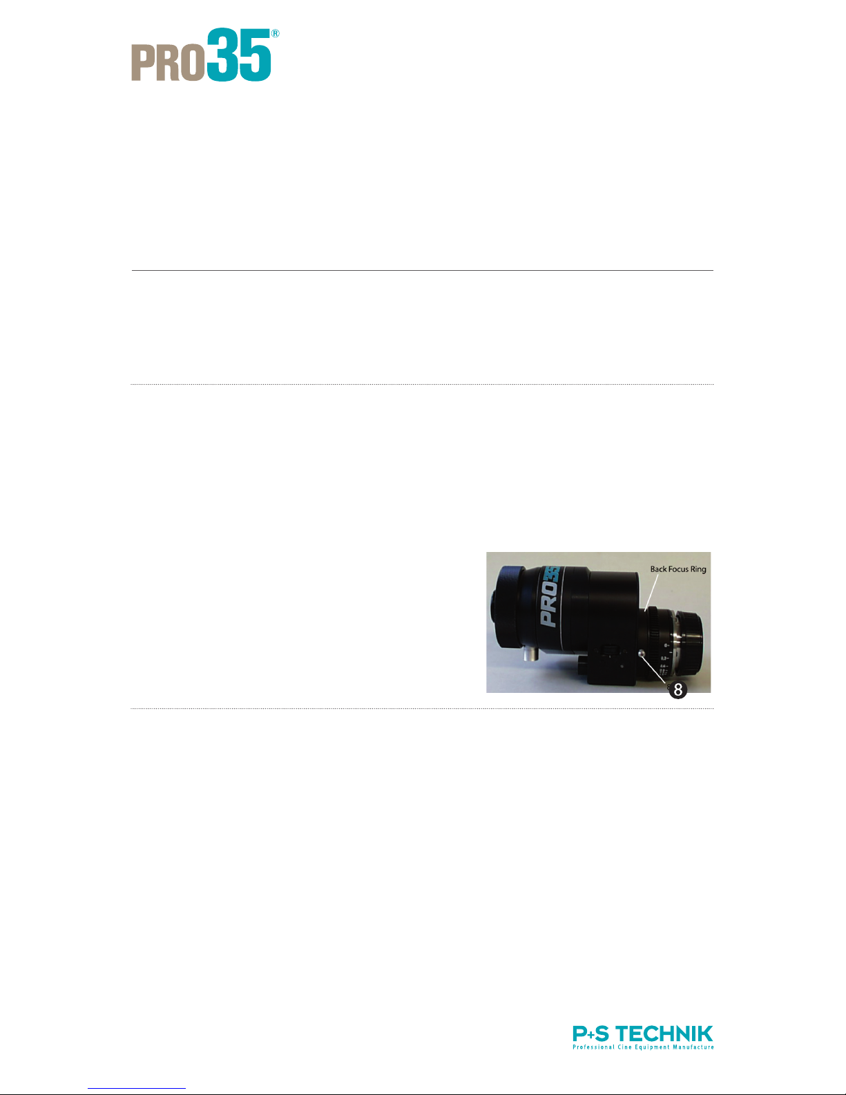
Unscrew the lever, marked 8in the photo.
Turn the ring to adjust for best sharpness.
Tighten lever 8.
The PRO35 Image Converter is precisely ad-
justed for the camera.
Explanatory Notes
Select a mid range film lens; around
50mm.
Use a good quality monitor to evalua-
te the picture.
20
2. Adjusting flange focal distance in the field:
Rule of thumb: If you are seeing the structure of the target glass clearly sharp while having
switched off the Image Converter (OFF), the flange focal distance is correctly adjusted.
1
2
2.1
2.2
2.3
2.4
Instruction
Mount a film lens to the PRO35.
Use a white chart.
Turn the PRO35 unit OFF.
Open the adjustable “ND filter” to Position 0.
Close the iris of the film lens far enough to allow
the video camera to show the grain pattern of the
target glass.
Unscrew lever h(shown labelled in photo), and
turn the ring to adjust the sharpness.
Tighten lever h.
When the grain pattern is sharp, the PRO35 is pre-
cisely adjusted for the camera.
Explanatory Notes
Select a mid range film lens
(around 50mm)
Set a white chart at a reasonable
distance to fill the image.

21
E
Setup
2
Example for test charts
Test charts to control the back focus are available from P+S Technik, or:
ZGC (Putora)
http://www.zgc.com/zgc.nsf/product/putora
Image Engineering (Esser)
http://digitalkamera.image-engineering.de/index.php/Produkte/Testcharts
DSC-Labs
http://dsclabs.com/resolution.htm
–
–
–
Table of contents


