Pratt Burnerd Atlas EZ Set User manual

1
Atlas EZ Set Manual
3977 Emerald Drive Kalamazoo, MI 49001
PH800-253-0820 Email: [email protected]
WEBSITE:WWW.PRATTBURNERD.COM

2
This instruction manual is for production engineers and
maintenance personnel in charge of operation of this
product. Please make sure that when a beginner uses this
product, they receive instructions from experienced
personnel, the distributor or PBA.
Before installing, operating or maintaining this equipment,
carefully read this manual. Failure to follow these
instructions and safety precautions could result in serious
injury, death, or property damage.
Store this manual near the equipment for future
reference.

3
Index
Please read this manual carefully to ensure an appropriate
use of your Atlas EZ Set chuck and pay special attention to
safety and maintenance instructions.
1. Parts list
2. Spare parts
3. General concepts and usage
4. Safety instructions
5. Technical specifications
6. Clamping capacity
7. Mounting adapter
8. Mounting chuck / EZ Set Feature
9. Maintenance
10. Warranty
4
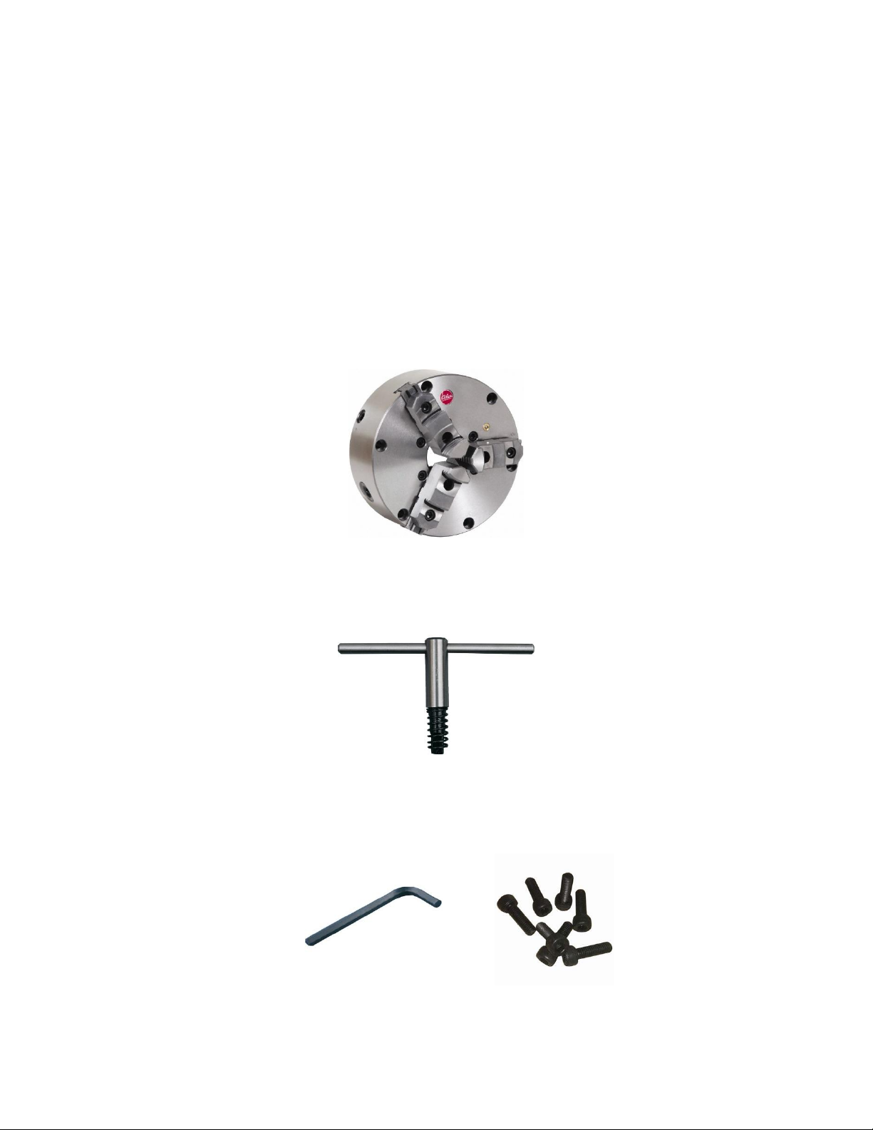
(1) Parts List
In your box, depending on the acquired chuck, you will find the
following:
Chuck with reversible hard top jaws
Operating key for pinions
Mounting bolts and Allen key

5
(2) Spare Parts
Available spare parts for your chuck are as follows:
(1) Scroll Gear
(2) Pinion Gear
(3) Base/Master jaw set
(4) Hard top jaw set
(5) Micro Adjustment screw
*Please consult factory for part numbers

6
(3) General Concepts
Atlas Workholding chucks are high quality products built
under technical and safety requirements. First class materials
are used in the building process to ensure long lasting life of
chuck. Atlas Workholding holds a large inventory of
replacements to guarantee your chuck is always in its best
possible condition.
Usage
Atlas Workholding chucks are designed to solve clamping
needs in any horizontal or vertical lathe from every brand
worldwide.
However, they can also be used to clamp any piece that
needs to be static in milling machines, machine centers,
drills, grinders and generally in any application that requires
precise concentric clamping.

7
(4) Safety
Ensure that your machine is turned off when installing and
changing the chuck.
Always consider that due to centrifugal force the clamping force
decreases as the revolutions of the lathe increases.
Never work over the maximum revolutions indicated.
Make sure that all the chuck mounting screws and screws
between the base and top jaw have been properly secured &
torqued.
When clamping, ensure hands are out of clamping area.
Always use safety glasses.
Never modify the chuck.
Make sure that jaws used are as light as possible.
Never neglect lubrication.
Never hit the chuck key with other tools or use a pipe to get
greater clamping force. Using the hand key that comes with the
chuck will be enough to get the maximum gripping force.
Use a tail stock when machining a long work piece.
When lifting the chuck use an eyebolt or lifting belt. Never
operate the machine under the influence of alcohol or drugs.
Gloves and ties should not be worn when operating the machine.
8
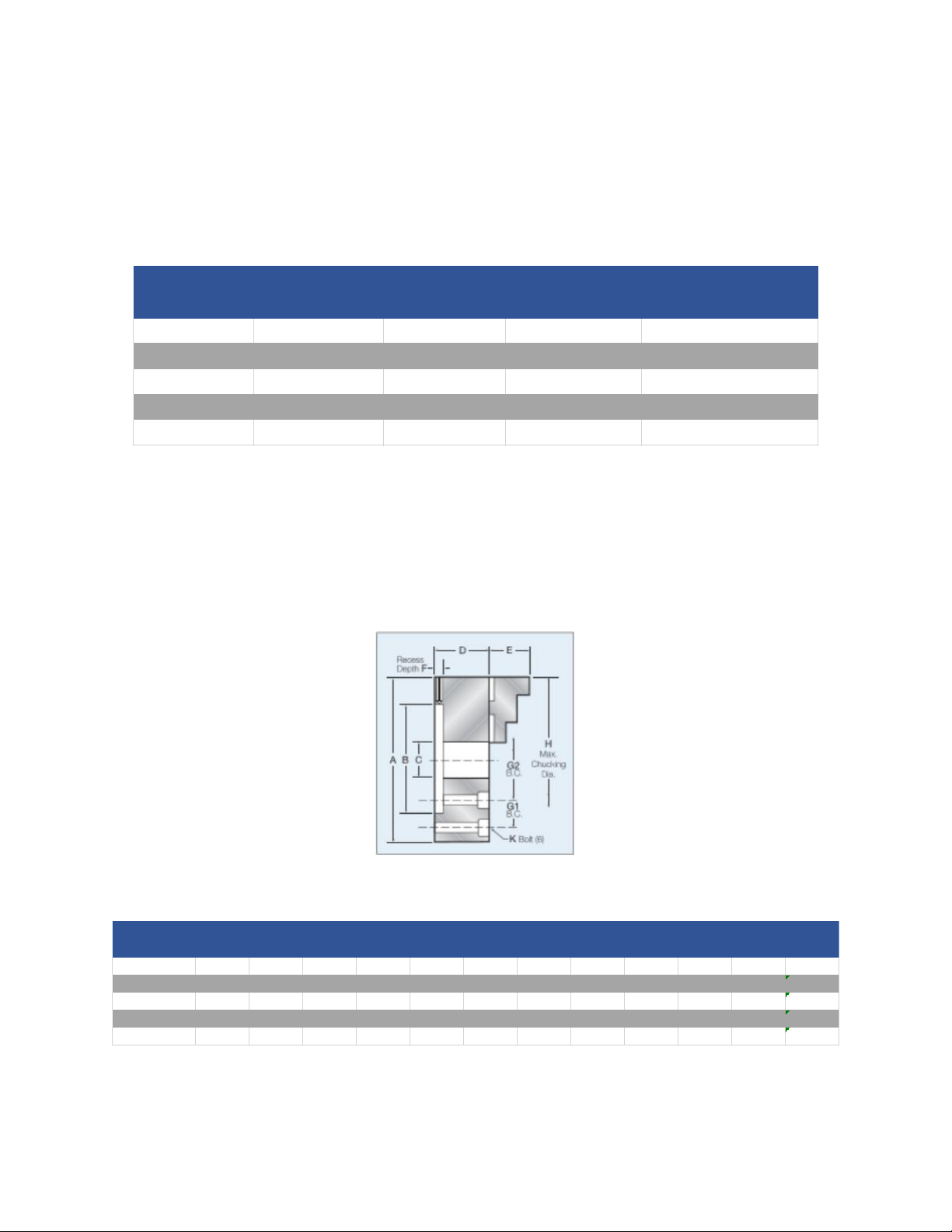
(5) Technical Specifications
Note: Maximum revolutions indicated are under optimal
machining conditions, with the center of gravity of the piece
placed at the center of the lathe bore
Chuck Max Input Output Force RPM Max Aproximate
Size Torque lbs/f lbs/f Weight
6 inch 55 7500 3000 20
8 inch 85 10500 2500 43
10 inch 115 12500 2000 67
12 inch 140 15000 1500 115
15 inch 140 16500 1000 225
Chuck
GRIPPING
CAPACITY
Size A B C D E F G1 G2 H K MIN MAX
6 inch 6 3.125 1.54 2.52 1.728 0.69 5.34 6.5 1/4 1/8 5
8 inch 8.25 4.75 2.362 3.122 1.141 0.732 7.5 8.5 3/8 3/16 6 1/2
10 inch 10 6.375 3.031 3.504 2.118 0.803 4.38 11 7/16 15/32 8
12 inch 12 7.906 4.055 4.035 2.492 0.799 5.25 12.5 1/2 27/64 10
15 inch 15 11.781 4.567 5.362 2.866 1.091 6.75 16 5/8 9/16 15

9
(6) Clamping capacity
Scroll chucks minimum clamping dimension may change based
on the thru bore of the chuck. The max clamping capacity will
not change. The maximum amount of master jaw extended
outside the chuck body should never exceed 25% of its length.
Extended length jaws can be used to grip smaller diameters.
Refer to technical specifications for Max and Min clamping
capacities.

10
(7) Adapter Mounting
Atlas EZ set chucks are precision manufactured for adapter
plate mounting. We offer a full line of mounting plates to fit
types “D”, “A”, “L” and threaded spindles. Special adapters to
fit different applications are also available, including rotary
table adapters.
Every surface of lathe spindle and adapter should be clean,
making sure that neither of them have been damaged.
Lathe spindles should be checked radial and axially.
Maximum error should be less than .0002”.
Adapter should be checked on the chuck side face, close to
the mounting holes. Error should be less than .0005”
If the error exceeds the .0005” take a truing cut across the
face of the adapter to true it with your spindle.

11
(8) Chuck Mounting / EZ Set
Feature
The Atlas EZ set feature has been designed to compensate
for any inaccuracy which may be introduced in mounting
the chuck and spindle nose adapter.
At the rear of the chuck body periphery there are 4 dog
point screws. These control float between the chuck body
and the spindle nose adapter.
The Atlas EZ set feature is easy to use. After following the
instructions in section (7) mounting. Ensure all mating
surfaces are thoroughly cleaned. The chuck should be
mounted with the through mounting bolts lightly hand
tightened. Check the runout on the chuck periphery using
a suitably positioned dial indicator. Adjust the 4
adjustment screws to obtain optimum accuracy. Fully
tighten the mounting bolts to the specification below.
Once set the chuck will require no further adjustment.
The chuck will repeat on duplicate parts within .0005”
Chuck Bolt Max mount bolt
Size Size Torque lbs/f
6 inch 1/4" 10
8 inch 3/8" 20
10 inch 7/16" 25
12 inch 1/2" 30
15 inch 5/8" 35

12
(9) Maintenance
Treating your chuck carefully applying grease to friction
areas periodically will make the chuck last longer and with
greater precision. To get the best possible precision in
second operations, soft jaws should be machined to the
chuck. It should be remembered that to turn the soft jaws,
all slack of the mechanism must be eliminated. Use of a
boring ring or pin would be recommended.
Clean and lubricate the chuck regularly with Pratt Burnerd
Americas PB160Z chuck lubricant. To obtain greater
efficiency, old grease and dirt should be removed before
lubricating again.
Chuck damages are mostly due to improper usage. Most
common damages could be avoided if:
oOnly the correct key is used in the pinion
oCheater bars/pipes are not used to turn the chuck key
oLathe is not turned on until everything is in its place
oKey is removed from pinion before turning of lathe
oChuck is not used for too heavy or too large parts
oNever grip pieces that are larger than the chuck diameter
A chuck is a precision tool that deserves to be treated the best
possible way. Pratt Burnerd America is not liable for damages
due to misuse of the chuck.

13
(10) Warranty
PBA/Atlas Workholding guarantees the correct functioning
of its products under normal conditions for a period of 1
year. This covers workmanship, specified accuracy and
material defects.
PBA/Atlas Workholding will repair or replace at our
discretion the part, or the entire product and include labor
if found defective.
PBA/Atlas Workholding is not responsible for any resulting
down time or resulting physical damage caused from a
defective product.
The warranty is void if the product is found to be misused
or used in a way it was not intended for.
All warranty claims are subject to inspection by PBA/Atlas
Workholding in our facility in Kalamazoo, Michigan.
Any item returned for warranty claim MUST be freight
prepaid.

14
Table of contents
Other Pratt Burnerd Industrial Equipment manuals

Popular Industrial Equipment manuals by other brands

Endress+Hauser
Endress+Hauser Hart Proline Promag P 500 Special Documentation

Showa Denki
Showa Denki CRN Series Operation manual

ABB
ABB HT581063 Operation manual

Shini
Shini SAL-810 manual

Raychem
Raychem nvent CE16-05 installation instructions

Global Industrial
Global Industrial B237006 Assembly instructions


