Pratt Burnerd Gripsafe User manual

Gripsafe
Operators manual
...... for your safety and peace of mind.

2
Contents:
1. Introduction
2. Specification and features
3. Packing case contents
4. Quick start reference guide
5. Initialising the Gripsafe
6. Charging the Gripsafe device using the USB connector
7. Charging the tablet using the USB connector
8. Switching on/off Gripsafe
9. Connect Gripsafe to the tablet web browser using Wi-FI
10. Displaying the Gripsafe Home page on the tablet web browser
11. Web page display and navigation
12. Clamping Gripsafe in the chuck jaws
13. Using the extension adaptor ring and pins
14. Measuring chuck jaw clamping force
15. Measuring rotational speed (rpm)
16. Connect Gripsafe to a pc
17. Spare parts

1. Introduction
The PBI GripSafe
gripmeter is a vital necessity for Health &
environment. From Centre Lathe to full CNC, whether industrial or Educational,
afford to ignore loss of grip.
Avoid long and tedious calculations
measure the grippi
ng force being applied by the chuck under both static and rotating conditions.
The GripSafe provides a host of valuable features utilising the latest “state of the art” Wi
communication technology with it’s unique embedded software application providing
data collection and analysis.
2. Specification and features
I.
Static & Dynamic chuck gripping force measurement
II.
Measures gripping force up to 100kN per jaw
III.
3 & 2 jaw chuck compatibility
IV.
Measures rotational speed up to maximum of 6000rpm
V. Wi-Fi
communications to any Wi
VI.
Rechargeable battery with mini
VII.
Extension rings to enable use with increased diameters
Ø116mm
extension pins A
VIII.
No additional software requ
IX.
Battery level software indicator
X.
Real Time data capture
XI.
Multiple machine file save feature
XII.
Data export to .CSV file function
gripmeter is a vital necessity for Health &
Safety within the machine
environment. From Centre Lathe to full CNC, whether industrial or Educational,
you cannot
Avoid long and tedious calculations
–
The GripSafe is the most reliable way to accurately
ng force being applied by the chuck under both static and rotating conditions.
The GripSafe provides a host of valuable features utilising the latest “state of the art” Wi
communication technology with it’s unique embedded software application providing
Static & Dynamic chuck gripping force measurement
Measures gripping force up to 100kN per jaw
3 & 2 jaw chuck compatibility
Measures rotational speed up to maximum of 6000rpm
communications to any Wi
-Fi compatible device
Rechargeable battery with mini
-B USB charging interface
Extension rings to enable use with increased diameters
(Ø72mm
standard
extension pins A
/ Ø160mm extension pins B)
No additional software requ
ired –
application software embedded into GripSafe unit
Battery level software indicator
Real Time data capture
Multiple machine file save feature
Data export to .CSV file function
Safety within the machine
you cannot
The GripSafe is the most reliable way to accurately
ng force being applied by the chuck under both static and rotating conditions.
The GripSafe provides a host of valuable features utilising the latest “state of the art” Wi
-Fi
communication technology with it’s unique embedded software application providing
extensive
standard
/
application software embedded into GripSafe unit
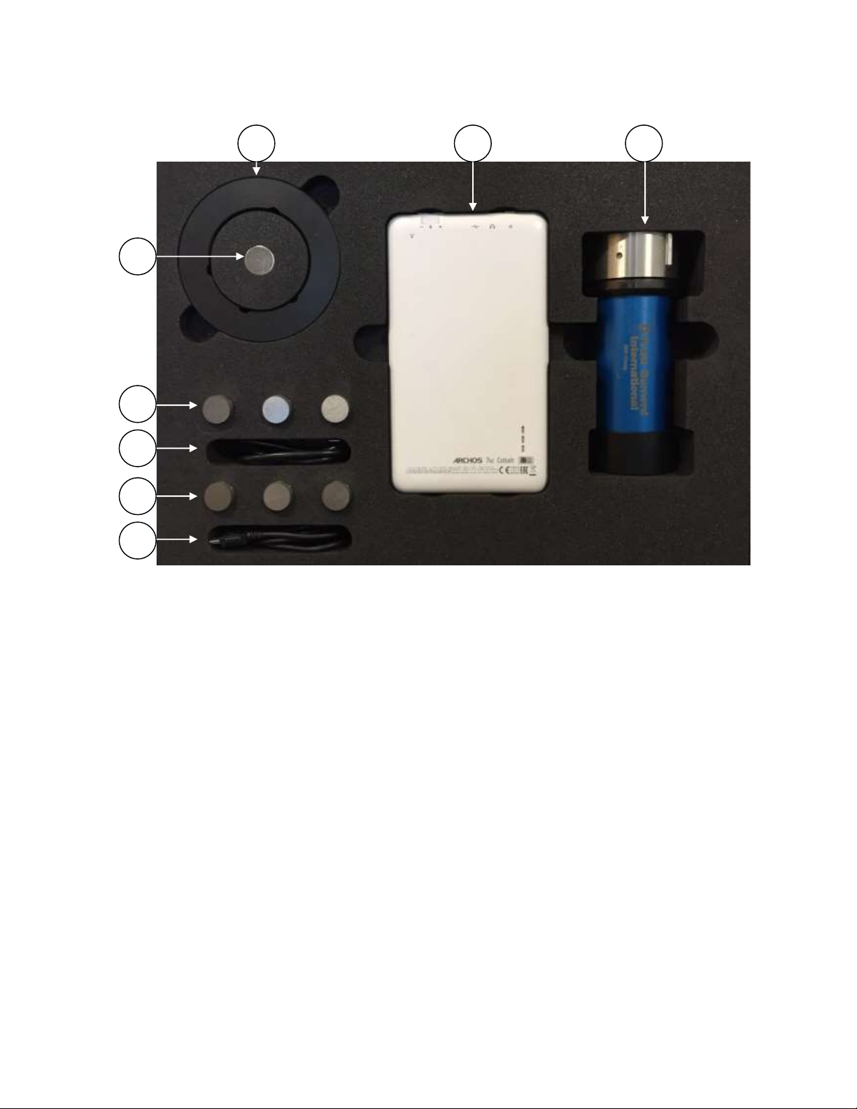
3. Packing case contents
a. Gripsafe chuck jaw force measuring unit
b. 7” colour Android touch screen tablet complete with Wi-Fi interface and micro-B
USB charging connection.
c. Gripsafe USB charger / communication cable (USB A to USB mini-B)
d. Tablet USB charger / communication cable (USB A to USB micro-B)
e. Extension pins type A for Ø116mm gripping
f. Extension pins type B for Ø160mm gripping
g. Extension pin adaptor ring
h. Magnet for rotational speed measurement
a
b
g
h
f
d
e
c

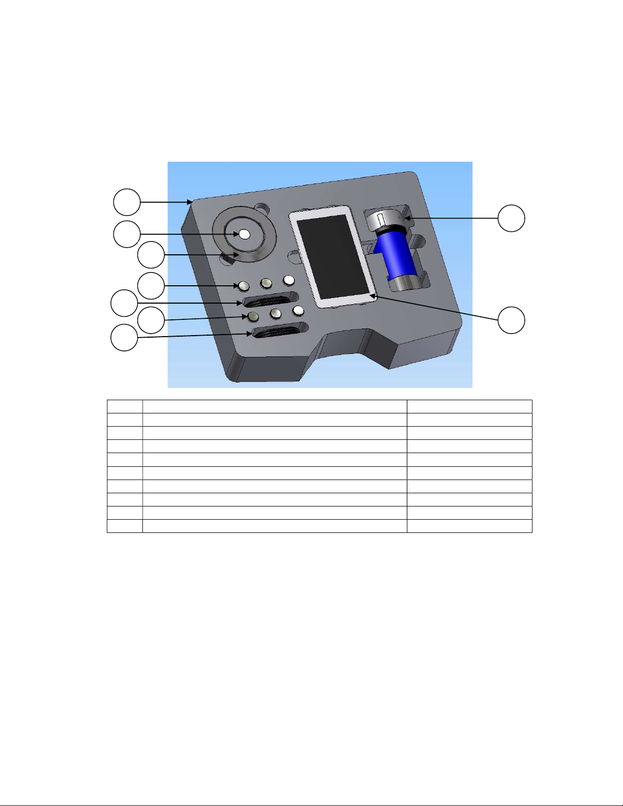
4. Quick start reference guide
4.1 Gripsafe jaw force measurement unit
a. USB mini-B charging / communication socket.
I. Connect to a PC or external USB mains charger to charge the Gripsafe unit using
the cable supplied. Full charge could take approximately 8 hours.
Note: The Gripsafe unit must be connect to either a PC or mains charger and fully
charged prior to first use.
II. Connect to PC using cable supplied to transfer saved files from Gripsafe unit.
Note: Files are saved as .CSV (Comma Separated Values) within the Gripsafe unit.
b. On / Off push button
I. Press once to switching on the Gripsafe unit.
II. Press and hold for 3 second to switch off the Gripsafe unit
c. Status LED.
I. LED display OFF – Gripsafe switched off
II. LED display ON Green, flashing slowly (1s on / 200ms off) – Gripsafe on and
ready to use
III. LED display ON Green, permanently on – Gripsafe power-up routine running
IV. LED display ON Green, flashing quickly (200ms on / 200ms off) – Gripsafe power-
off routine running
V. LED display ON RED – Gripsafe charging and off
Note: LED can display both RED and GREEN status at the same time.
d. Chuck Jaw clamping pins for 2 and 3 jaw chucks.
Note: Never clamp the chuck jaws onto the main body of the Gripsafe unit, always
use the integrated clamping pins provided. Failure to adhere to this may result in
damage to the Gripsafe device.
a
b
c
d
6
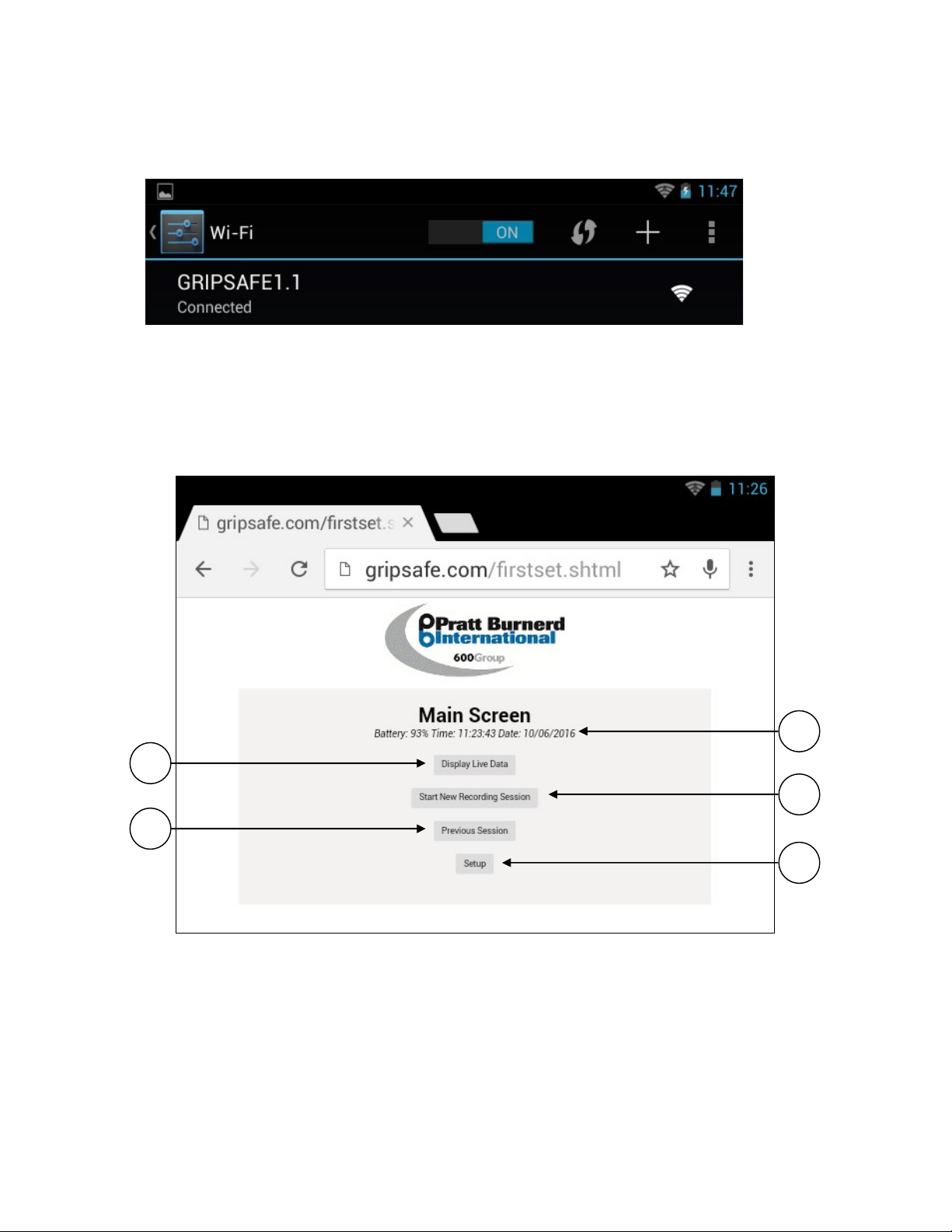
4.2 Connecting to Gripsafe using WI-FI
Select GRIPSAFE 1.x from the Wi-Fi setting page on the tablet.
4.3 Web browser and Gripsafe HOME page
Enter GRIPSAFE.COM into the tablet web browser app’ address bar. The HOME page will be
displayed as shown below.
a. Battery charge status display & Current time and date display
b. Display live data (chuck gripping force and rotational speed)
c. Record and save data (chuck gripping force and rotational speed)
d. Display saved files
e. Set-up (factory use only)
a
c
e
b
d

5. Initialising the Gripsafe
Before
using the Gripsafe unit for the first time, you must connect the Gripsafe to an external
mains charger or to a PC using the USB cable provided (US
initialise the Gripsafe unit
and enable it to be used.
ever the main rechargeable battery is disconnected or changed. Once connected, the status LED
will be illuminated pe
rmanently green as the power
approximately 5 seconds the Led will also illuminate red indicating that the Gripsafe is also
charging.
Press and hold the on / off push button for 3 seconds to switch off the Gripsafe. The sta
will flash quickly
(200ms on / 200ms off)
Note: The status LED will continue to be illuminated red as the device continues to charge.
You must charge the Gripsafe fully before first use. The charg
hours to fully charge.
Note:
External mains charger not supplied
6.
Charging the Gripsafe device
To charge the Gripsafe unit, connect to an external mains charger or to a PC using the USB cable
provided (USB type-
A to USB type mini
indicate that the charging sequence is taking place. The charging sequence could take up to 8
hours to fully charge.
Note:
External mains charger not supplied
7.
Charging the tablet using the USB connector
To charge the tablet, connect to an external mains charger or to a PC using the USB cable
provided (USB type-
A to USB type micro
fully charge. Please refe
r to the tablet user manual for additional advice and information relating
to charging the tablet.
Note:
External mains charger not supplied
8. Switching On / Off Gripsafe
Press the green on / off pushbutton on the Gripsafe to switch on the device. The status LED will
immediately illuminate green to indicate that the Gripsafe power
initialised. After approximately 5 seconds the status LED will slowly fla
indicating that the power-
up sequence has been
use. The status LED will continue to flash slowly while ever the Gripsafe is
To switch off the Gripsafe, press and hold th
seconds. The status LED will begin to flash quickly
using the Gripsafe unit for the first time, you must connect the Gripsafe to an external
mains charger or to a PC using the USB cable provided (US
B type-
A to USB type mini
and enable it to be used.
Note
: This action must also be carried out if
ever the main rechargeable battery is disconnected or changed. Once connected, the status LED
rmanently green as the power
-
up sequence is carried out. After
approximately 5 seconds the Led will also illuminate red indicating that the Gripsafe is also
Press and hold the on / off push button for 3 seconds to switch off the Gripsafe. The sta
(200ms on / 200ms off)
as the Gripsafe executes it’s power-
down sequence.
Note: The status LED will continue to be illuminated red as the device continues to charge.
You must charge the Gripsafe fully before first use. The charg
ing sequence could take up to 8
External mains charger not supplied
Charging the Gripsafe device
using the USB connector
To charge the Gripsafe unit, connect to an external mains charger or to a PC using the USB cable
A to USB type mini
-B). When connected, t
he status LED will illuminate red to
indicate that the charging sequence is taking place. The charging sequence could take up to 8
External mains charger not supplied
Charging the tablet using the USB connector
To charge the tablet, connect to an external mains charger or to a PC using the USB cable
A to USB type micro
-
B). The charging sequence could take up to 8 hours to
r to the tablet user manual for additional advice and information relating
External mains charger not supplied
Press the green on / off pushbutton on the Gripsafe to switch on the device. The status LED will
immediately illuminate green to indicate that the Gripsafe power
-
up sequence has been
initialised. After approximately 5 seconds the status LED will slowly fla
sh
(1s on / 200ms off)
up sequence has been
completed and the Gripsafe is n
ow ready to
use. The status LED will continue to flash slowly while ever the Gripsafe is
on and
ready to use.
To switch off the Gripsafe, press and hold th
e green on / off push button for approximately 3
seconds. The status LED will begin to flash quickly
(200ms on / 200ms off)
indicating the Gripsafe
using the Gripsafe unit for the first time, you must connect the Gripsafe to an external
A to USB type mini
-B). This will
: This action must also be carried out if
ever the main rechargeable battery is disconnected or changed. Once connected, the status LED
up sequence is carried out. After
approximately 5 seconds the Led will also illuminate red indicating that the Gripsafe is also
Press and hold the on / off push button for 3 seconds to switch off the Gripsafe. The sta
tus LED
down sequence.
Note: The status LED will continue to be illuminated red as the device continues to charge.
ing sequence could take up to 8
To charge the Gripsafe unit, connect to an external mains charger or to a PC using the USB cable
he status LED will illuminate red to
indicate that the charging sequence is taking place. The charging sequence could take up to 8
To charge the tablet, connect to an external mains charger or to a PC using the USB cable
B). The charging sequence could take up to 8 hours to
r to the tablet user manual for additional advice and information relating
Press the green on / off pushbutton on the Gripsafe to switch on the device. The status LED will
up sequence has been
(1s on / 200ms off)
ow ready to
ready to use.
e green on / off push button for approximately 3
indicating the Gripsafe
power-
down sequence has been initialised. The power
seconds. Once the Gr
ipsafe has successfully powered
9
. Connecting Gripsafe to the tablet web browser using Wi
Switch on the Gripsafe unit and ensure that the status LED is illuminated green and flashing
slowly (1s on / 200ms off)
to indicate that the Gripsafe is ready to use.
Switch on the tablet and
ensure that Wi
GRIPSAFE 1.x
from the devices listed. The tablet will
Note: Please refer t
o the tablet user manual for additional advice and information relating to
setting up and connecting with Wi
10.
Displaying the Gripsafe home page on the tablet web browser
Switch on the Gripsafe unit and ensure that the status LED is ill
slowly (1s on / 200ms off)
to indicate that the Gripsafe is ready to use.
Switch on the tablet and ensure that GRIPSAFE 1.x is connected and that the Wi
range of the Gripsafe unit.
Select and launch the web brows
bar of the web browser,
gripsafe.com
load.
11
Web page display and navigation.
11.1 Home Page.
a.
Current percentage of battery charge remaining.
b.
Current time and date.
c.
Select Display Live Data screen
d.
Select Start New Recording Session screen
e.
Select Previous Session screen
f.
Select Setup screen.
factory use only.
a
down sequence has been initialised. The power
-
down sequence takes approximately 3
ipsafe has successfully powered
-
down, the status LED will be extinguished.
. Connecting Gripsafe to the tablet web browser using Wi
-Fi
Switch on the Gripsafe unit and ensure that the status LED is illuminated green and flashing
to indicate that the Gripsafe is ready to use.
ensure that Wi
-Fi is enabled. Navigate to the Wi-
Fi setting page.
from the devices listed. The tablet will
now
connect to the Gripsafe unit.
o the tablet user manual for additional advice and information relating to
setting up and connecting with Wi
-Fi on the tablet.
Displaying the Gripsafe home page on the tablet web browser
Switch on the Gripsafe unit and ensure that the status LED is ill
uminated green and flashing
to indicate that the Gripsafe is ready to use.
Switch on the tablet and ensure that GRIPSAFE 1.x is connected and that the Wi
-
Fi signal is in
Select and launch the web brows
er App on the tablet. Type the following address in the address
gripsafe.com
and select enter. The Gripsafe Home Page will now
Web page display and navigation.
Current percentage of battery charge remaining.
Current time and date.
Select Display Live Data screen
Select Start New Recording Session screen
Select Previous Session screen
Select Setup screen.
Note:
this screen is not accessible for users and is fo
factory use only.
c
b
d
e
f
down sequence takes approximately 3
down, the status LED will be extinguished.
Switch on the Gripsafe unit and ensure that the status LED is illuminated green and flashing
Fi setting page.
Select
connect to the Gripsafe unit.
o the tablet user manual for additional advice and information relating to
uminated green and flashing
Fi signal is in
er App on the tablet. Type the following address in the address
and select enter. The Gripsafe Home Page will now
this screen is not accessible for users and is fo
r

11.2 Display Live Data page.
Select the Display Live Data button from the Home page
a. Current percentage of battery charge remaining.
b. Current time and date.
c. Real time rotational speed measurement in r.p.m.
d. Real time chuck jaw clamping force measurement in kN
e. Real time graphical display of rotational speed and chuck jaw clamping
force measurements. Note: The left hand y-axis scale and red line
represents the measure clamping force. The right hand y-axis scale and
blue line represents the measured rotational speed.
f. Exit to Home page button.
e
b
a
c
d
f
10
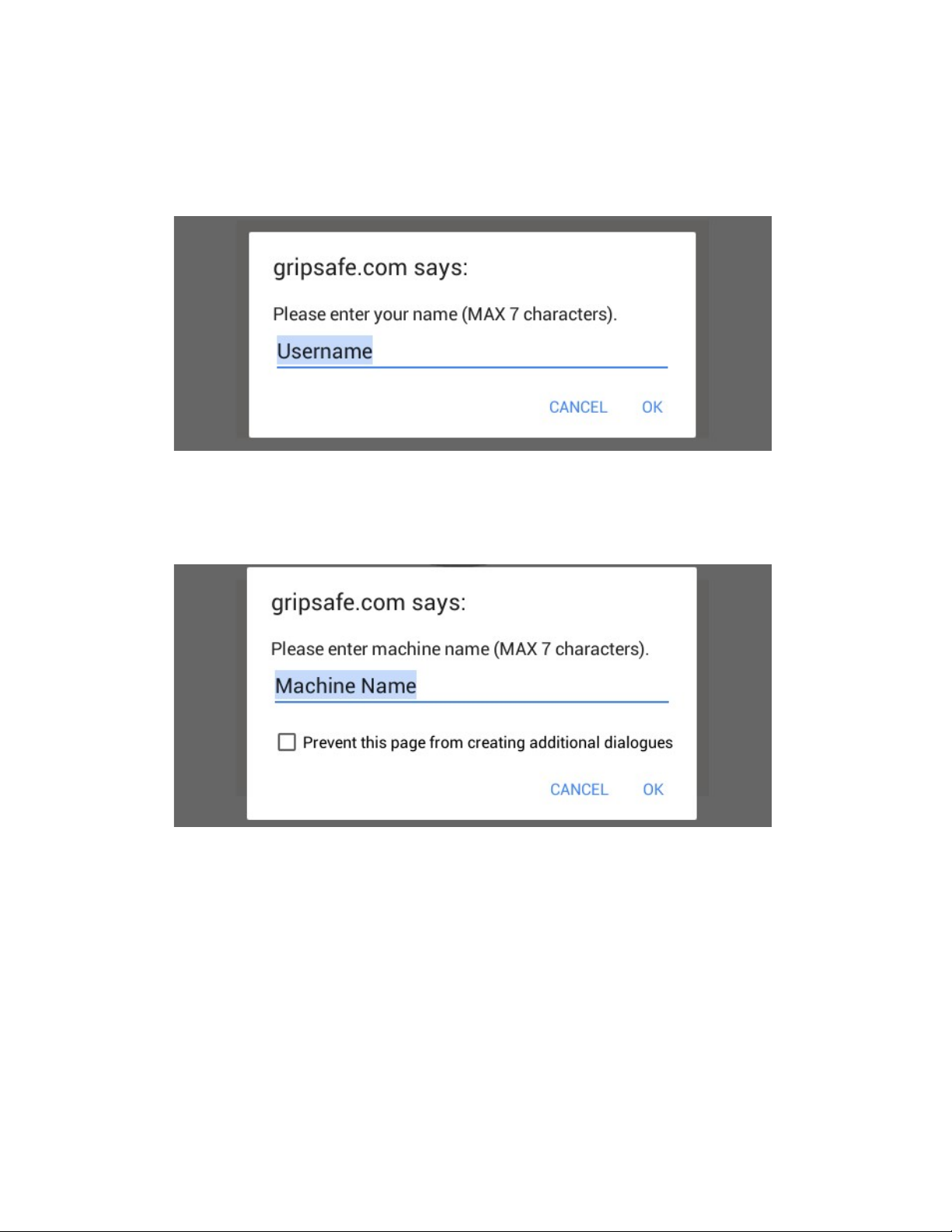
11.3 Start New Recording Session page.
Select Start New Recording Session from the Home page.
The following dialogue box will appear prompting the user to enter their name.
Enter your name or other reference using the keypad displayed on the tablet and then select OK.
The following dialogue box will appear prompting the user to enter a machine reference
number.
Enter the machine serial number or other reference using the keypad displayed on the tablet and
then select OK.
The Record New Session screen will now be displayed.
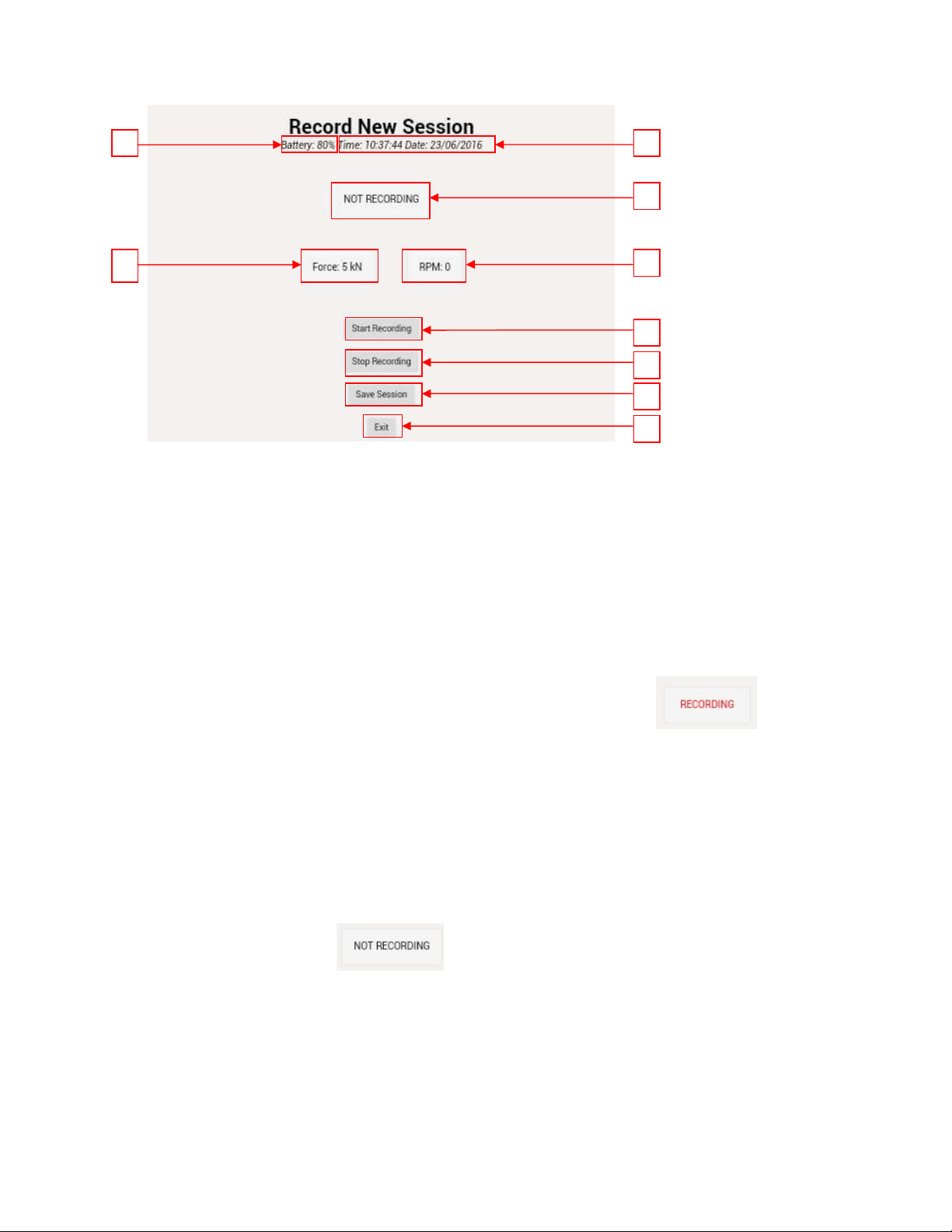
a. Current percentage of battery charge remaining.
b. Current time and date.
c. Start Recording button
d. Stop Recording button
e. Save Session button
f. Exit to Home page button.
g. Live clamping force data
h. Live rotational speed data
i. Recording status bar
Select the Start Recording button. The recording status bar will change to
to indicate that recording has begun. Also the status LED sequence will now change (to 2s on / 1s
off / 1s on / 2s off), to indicate that recording mode is active. Note: Ensure recording mode is
active before continuing.
Gripsafe will now begin to automatically record chuck jaw clamping force and rotational speed
data. Note: Chuck jaw clamping force data will only be recorded when a minimum of 50rpm
change in rotational speed is measured.
Once a recording session has been completed, select the Stop Recording button. The recording
status bar will change to to indicate that recording has finished. Also The status
LED will return to the slow flash sequence (1s on / 200ms off) indicating that recording mode is
now inactive. Note: Ensure recording mode is inactive before proceeding.
Select the Save Session button to save the recorded data to the internal memory of the Gripsafe
unit.
Select the Exit button to return the Home page.
c
b
d
e
f
a
h
g
i

11.4. Previous Session Page
a. Current percentage of battery charge remaining.
b. Current time and date.
c. List of saved files
d. Display next page of saved files
e. Display previous page of saved files
f. Exit to Home page button.
g. Access and display selected saved file data
To access a previously saved file, select and highlight the desired file and then select the Access
File Data button. The recalled data will be displayed in graphical format.
a. Current percentage of battery charge remaining.
b. Current time and date.
c
b
d
f
g
.
a
e
c
b
a
c. Exit to Previous Session page button.
11.5 Setup page
The set-up page is password protected and is for factory set-up use only.
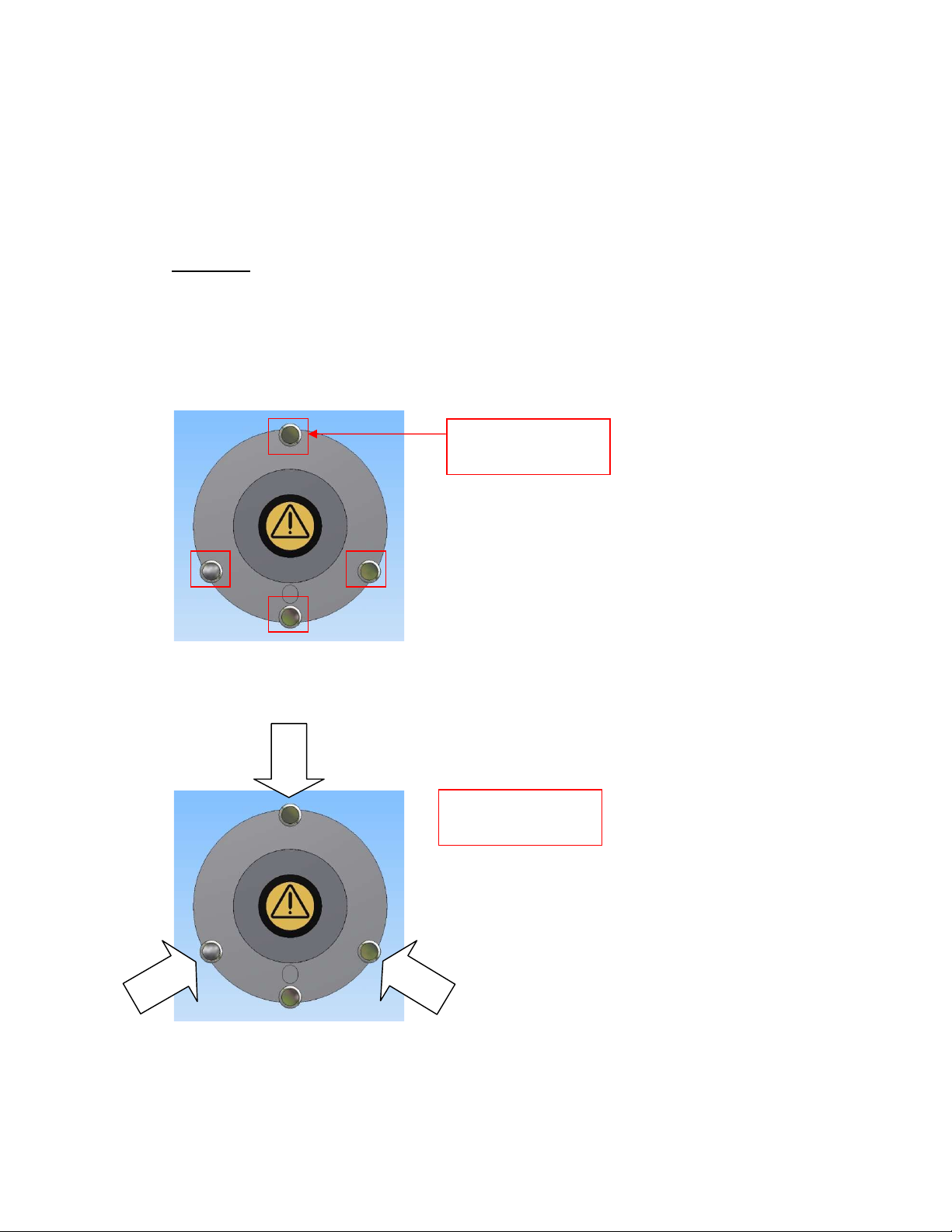
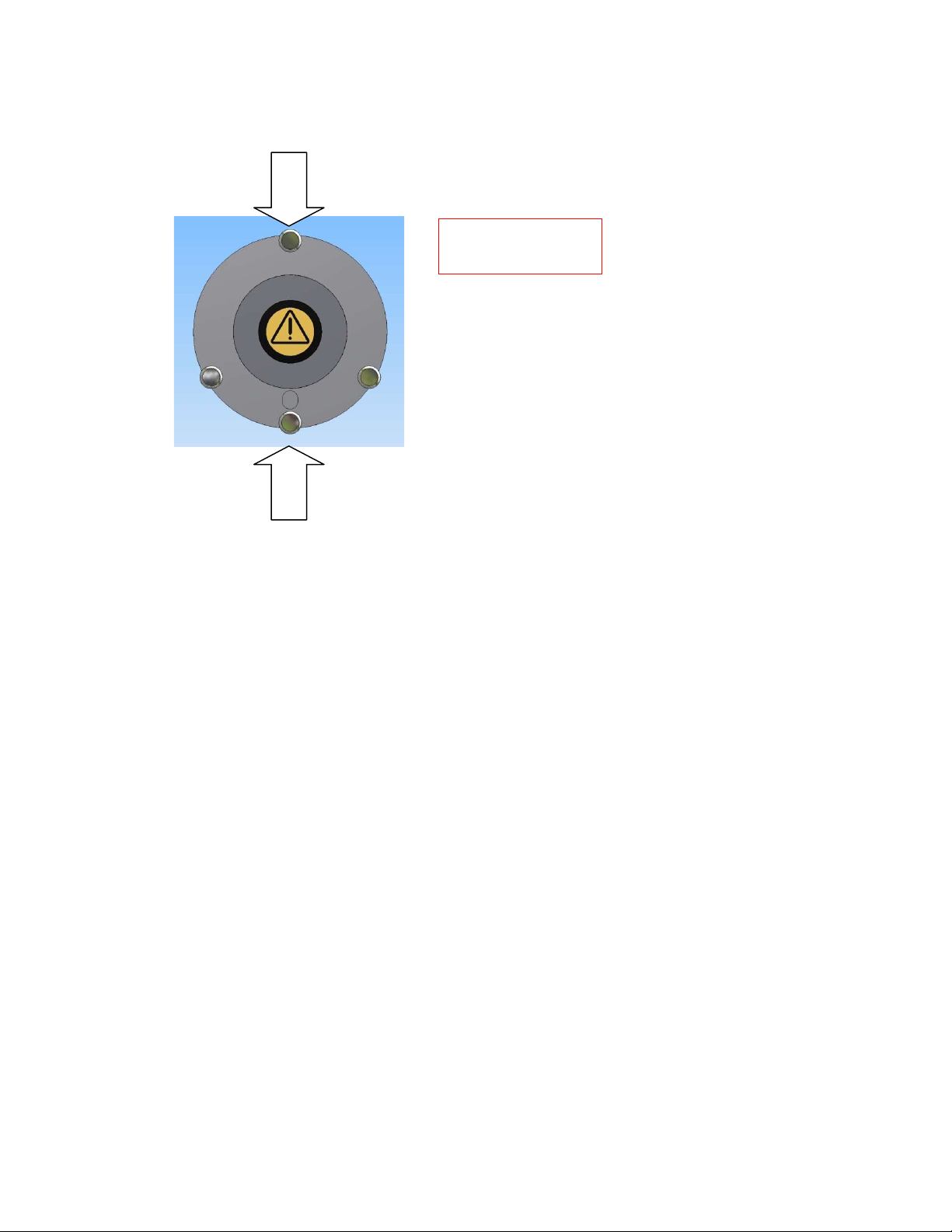
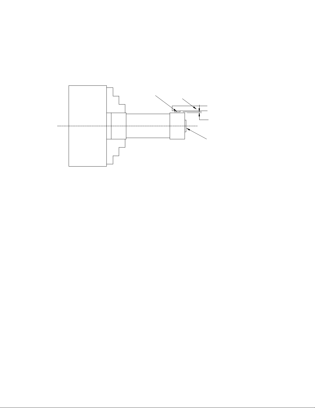
12. Clamping Gripsafe in the chuck jaws
Safety Note: Always read and observe the relevant manufacturer’s safety information prior to
using any chuck or machine.
Integrated into the Gripsafe unit are dedicated hardened clamping pins which must be used to
clamp the Gripsafe into any chuck or vice.
The Gripsafe unit can measure the chuck jaw clamping force of both three jaw chucks and 2 jaw
chucks and vices.
Integrated clamping
pins.
Clampi
ng points for
3-jaw chuck.
The chuck jaws should be adjusted to grip a diameter of 72mm at the mid stroke position. If the
extension adaptor ring and pins are being used, the position of the top jaws should be selected
accordingly. When measuring dynamic gripping force i.e. with the chuck rotating, the top jaws
should preferably be positioned as near to the actual position that they will occupy when
gripping the intended workpiece.
Open the chuck jaws and insert the Gripsafe. Close the chuck to clamp the Gripsafe ensuring
that the chuck jaws clamp securely onto the integrated clamp pins. Note: Always clamp the
chuck jaws onto the integrated clamp pins and not onto the body of the Gripsafe. Failure to do
so may result in damage to the Gripsafe unit.
Note: 4-Jaw independent chucks should be treated similarly to a 2-Jaw chuck with the gripping
force measured between two opposing jaws and with the other two jaws backed off so as not to
impose any load on the Gripsafe.
13. Using the extension adaptor ring and pins.
The Gripsafe can be adapted to measure the jaw clamping force of larger diameter three jaw
chucks and two jaw chucks and vices by the use of the extension adaptor ring and pins.
Two different sets of extension pins are provided which can increase the gripping diameter to
116mm by using the smaller (type-A) of the extension pins, and to a gripping diameter of
160mm by using the larger (Type-B) of the extension pins.
To fit the extension pins, firstly fit the extension ring adaptor onto the Gripsafe unit. The
Gripsafe unit has two location dimples on its periphery. The extension adaptor ring is fitted with
corresponding location ball detents. Slide the extension adaptor ring over the Gripsafe unit
Clamping points for
2-jaw chuck or vice
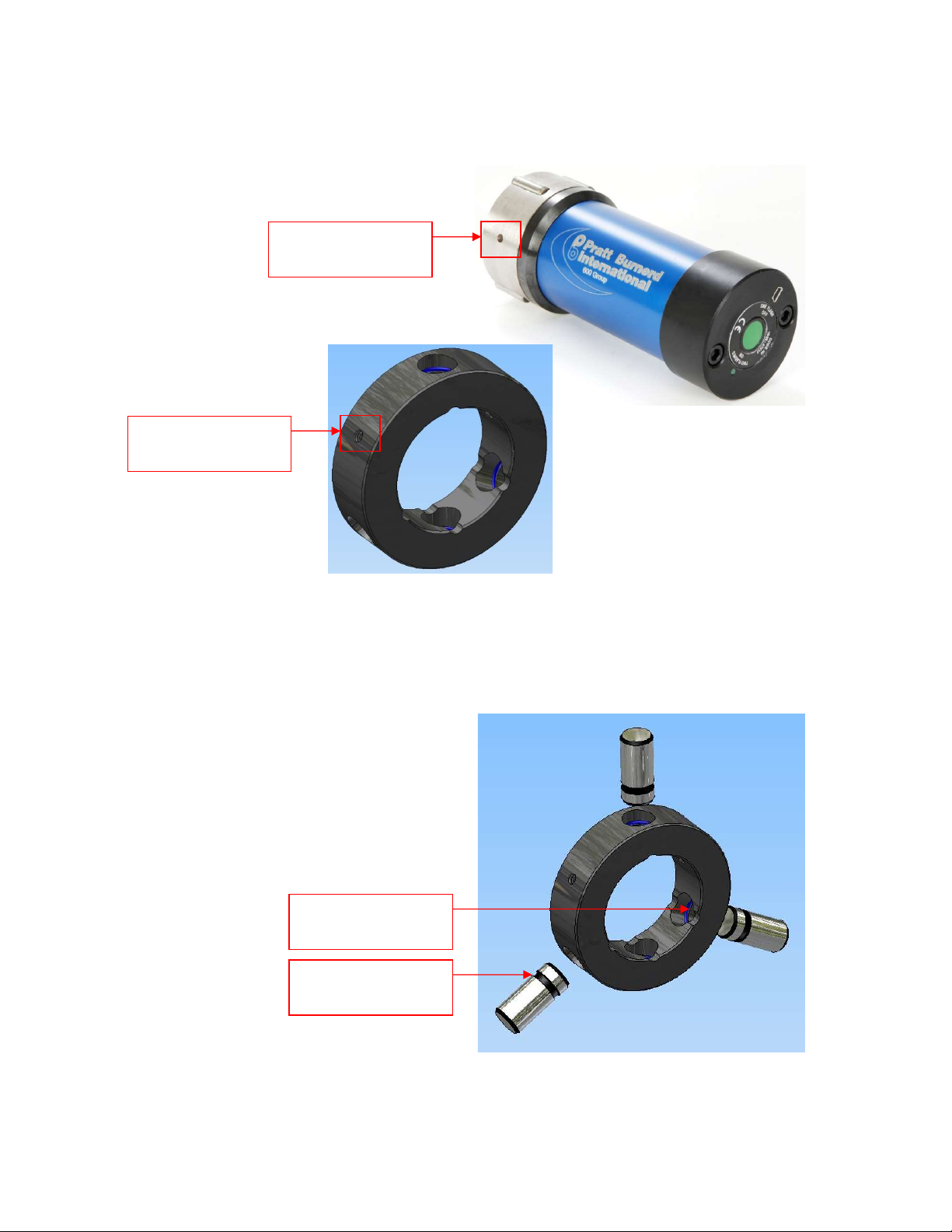
ensuring that the ball detents fall firmly into the two corresponding dimples on the periphery of
the Gripsafe unit.
Insert into the extension adaptor ring, the correct type and number of extension pins
appropriate to the type of chuck or vice being used. Each extension pin has a groove machined
into its circumference. The extension adaptor ring has a corresponding O-ring fitted to locate
around the extension pin groove.
Location dimple.
Location ball detent.
Extension pin groove.
Extension adaptor
ring O-ring.

16
Ensure that the extension pins are firmly located into the extension adaptor ring. Note: When
clamping onto the extension pins, ensure that the clamping load is applied centrally to the
extension pins.
14. Measuring chuck jaw clamping force.
Power-on Gripsafe and the tablet. On the tablet, connect to Gripsafe using Wi-Fi and navigate to
the Display Live Data page using the web browser. Position the Gripsafe unit in the open chuck
or vice jaws with the integrated clamping pins aligned with the centre of the Jaws. Close the
chuck or vice ensuring that the Gripsafe unit is clamped on the integrated clamping pins. Note:
Always ensure that the Gripsafe unit is inserted squarely into the chuck or vice. The static
clamping force measured in kN per jaw will be displayed on the Display Live Data page.
Do not overload the Gripsafe unit by attempting to measure forces in excess of its maximum
load rating capacity. The maximum load rating capacity is 100kN per jaw.
(1kN = 0.2248klbf = 0.102Mgf=0.1tonf)
Dynamic gripping force can be measured. The Gripsafe unit is rated up to a maximum rotational
speed of 6000rpm. Note: Never run the Gripsafe unit or work holding device in excess of its
maximum rated speed. Prior to operating the chuck at its maximum rated speed, it is advisable
to commence monitoring readings at a low speed and gradually increasing the speed observing
the fall-off in gripping force. Note: Do not allow the gripping force to fall to zero as the Gripsafe
unit could be ejected from the chuck jaws. The reduction in gripping force is proportional to the
square of the speed and causes the gripping force to fall-off steeply at high speeds.
15. Measuring rotational speed (rpm)
Power-on Gripsafe and the tablet. On the tablet, connect to Gripsafe using Wi-Fi and navigate to
the Display Live Data page using the web browser. Position the Gripsafe unit in the open chuck
or vice jaws with the integrated clamping pins aligned with the centre of the Jaws. Close the
17
chuck jaws ensuring that the Gripsafe unit is clamped on the integrated clamping pins. Note:
Always ensure that the Gripsafe unit is inserted squarely into the chuck or vice. To measure the
rotational speed of the Gripsafe unit, the magnet supplied should be attached to a suitable tool
holder, which in turn should be positioned adjacent to the Gripsafe unit.
Note: Always ensure that the magnet has a minimum air gap clearance of 5mm from the
Gripsafe unit, taking care to rotate the Gripsafe unit to check for any eccentricity before
attempting to rotate at speed.
The rotational speed will be displayed in revolutions per minute (rpm) on the Display Live Data
screen. The Gripsafe unit is rated up to a speed of 6000rpm. Note: Never run the Gripsafe unit or
work holding device in excess of its maximum rated speed.
16. Connect Gripsafe to a PC
Gripsafe can be connected to a pc to either recharge its battery or to download previously save
data files. To connect Gripsafe to a pc, use the USB type-A to USB type mini-B cable provided.
Once you have connected Gripsafe to the pc, charging will automatically begin. The status LED
will illuminate red to indicate charging mode is active. To view / transfer files from Gripsafe onto
the pc, switch on Gripsafe by pressing the on / off push button. The status LED will now also
illuminate green to indicate that the Gripsafe unit is on and connected to the pc. Note: the green
LED will not flash in power-on mode when connected to the pc. The Gripsafe is fitted with an
internal SD memory card which the pc will automatically detect and assign a drive letter to. The
SD card can be accessed from the pc using the usual pc file explorer app.
Recorded session data is stored on the Gripsafe SD card as a Comma Separated Value (CSV) file
type. The file contains data including, date and time of recording, measured gripping force and
measured rotational speed, battery charge status and operating temperature. The CSV file can
be copied or moved from the Gripsafe to the pc by using the usual pc file explorer app. CSV files
can be opened and viewed on the pc using many appropriate apps including MicroSoft Excel.
CHUCK
Gripsafe
JAWS
5mm MIN
ON / OFF
BUTTON
HOLDER
TOOL
MAGNET
10 mm MAX GAP
Note: One or more files named “CD_” are stored on the Gripsafe internal SD card. These two
files contain important information relating to the calibration of the Gripsafe unit. Never
attempt to view, modify or delete these files as this will result in errors with the Gripsafe
readings.
17. Spare parts list
Item
Description
Part Number Reference
a
Packing case including foam
PLASCASE
-
NPR8
b
Magnet
2009
-
73002
c
Extension adaptor ring
2009
-
06531
d
Extension pins
–
Small
2009
-
06532
e
USB cable
–
PC to Gripsafe
B998
-
0002
f
Extension pins
–
Large
2009
-
06533
g
USB cable
–
PC to tablet
B998
-
0003
h
Tablet
B998
-
0001
i
Gripsafe unit
1009
-
06531
a
b
c
d
e
f
g
i
h

19
NOTES:
Table of contents
Other Pratt Burnerd Industrial Equipment manuals

Popular Industrial Equipment manuals by other brands

Nord Drivesystems
Nord Drivesystems B 1000 Manual with installation instructions

Bosch
Bosch SCT 815 S3 Original operating instructions

DUUN
DUUN VM410 instruction manual

flexfactory
flexfactory flexfeeder X Series Assembly instructions

DÖRR
DÖRR EcoFlow LPF P Operation manual

RUD
RUD VCGH-S Series User instructions


Mecal
Mecal UNI MECAL VERSION Operation and maintenance manual

Parker
Parker 402XE Series product manual

Kistler
Kistler 9708A Series instruction manual

YoraHome
YoraHome 6550 user manual

Lincoln Electric
Lincoln Electric AEROMIG 3D Safety instruction for use and maintenance

Siemens
Siemens SIMATIC S7 300 PLC Getting started