TFP1640
Page 4 of 4
NATIONAL FIRE PROTECTION ASSOCIATION and NFPA are registered trademarks of National Fire Protection Association;
MONEL is a registered trademark of Special Metals Corporation
1400 Pennbrook Parkway, Lansdale, PA 19446 | Telephone +1-215-362-0700
© 2021 Johnson Controls. All rights reserved. All specifications and other information shown were current as of document revision date and are subject to change without notice.
Care and
Maintenance
The following procedure and inspec-
tions must be performed as indicated,
in addition to any specific requirements
of the NFPA� Any impairment must be
immediately corrected�
Before closing a fire protection system
main control valve for maintenance
work on the fire protection system
that it controls, obtain permission to
shut down the affected fire protection
system from the proper authorities
and notify all personnel who may be
affected by this action�
The owner is responsible for the inspec-
tion, testing, and maintenance of their
fire protection system and devices in
compliance with this document, as well
as with the applicable standards of the
NATIONAL FIRE PROTECTION ASSO-
CIATION (e�g�, NFPA 25), in addition to
the standards of any other authorities
having jurisdiction� Contact the install-
ing contractor or product manufacturer
with any questions�
Automatic sprinkler systems should be
inspected, tested, and maintained by a
qualified Inspection Service in accor-
dance with local requirements and/or
national code�
Maintenance Procedure
It is recommended that Model A strain-
ers be flushed at least annually� More
frequent flushing may be necessary
where water supplies are non-potable
and/or contain debris which could clog
1/3 or more of the basket open area�
Note: Never disassemble or remove
any strainer component without veri-
fying that the system is depressurized
and drained.
Strainers should be thoroughly flushed
clean after each system operation or
flow test and during routine inspections
as follows:
Step 1. Open flushing connection
valve (Ref� Design Criteria) allowing
flow until drain water runs clear� Close
valve�
Note: If heavy sediment in drain water
persists or there are indications that
all debris such as large stones may
not have been removed, basket must
be removed for cleaning; Proceed to
Step 2.
Step 2. Shut down and drain system�
Step 3. Remove end closure nuts and
bolts, flange and ring gasket�
Step 4. Withdraw basket in slow, hori-
zontal motion to minimize possibility of
debris falling from open inlet end into
body�
Step 5. Empty debris from basket and
clean body interior�
Step 6. Insert basket into body until
open inlet end is fully seated against
inlet connection flange�
Step 7. Install end closure gasket,
flange, and nuts and bolts� Gradually
tighten all nuts and bolts in cross-draw
sequence to apply uniform load around
flange�
Step 8. Ensure flushing connection
valve is closed�
Limited
Warranty
For warranty terms and conditions, visit
www�tyco-fire�com�
Ordering
Procedure
Contact your local distributor for avail-
ability� When placing an order, indi-
cate the full product name, including
description and part number (P/N)�
Standard Order Strainers
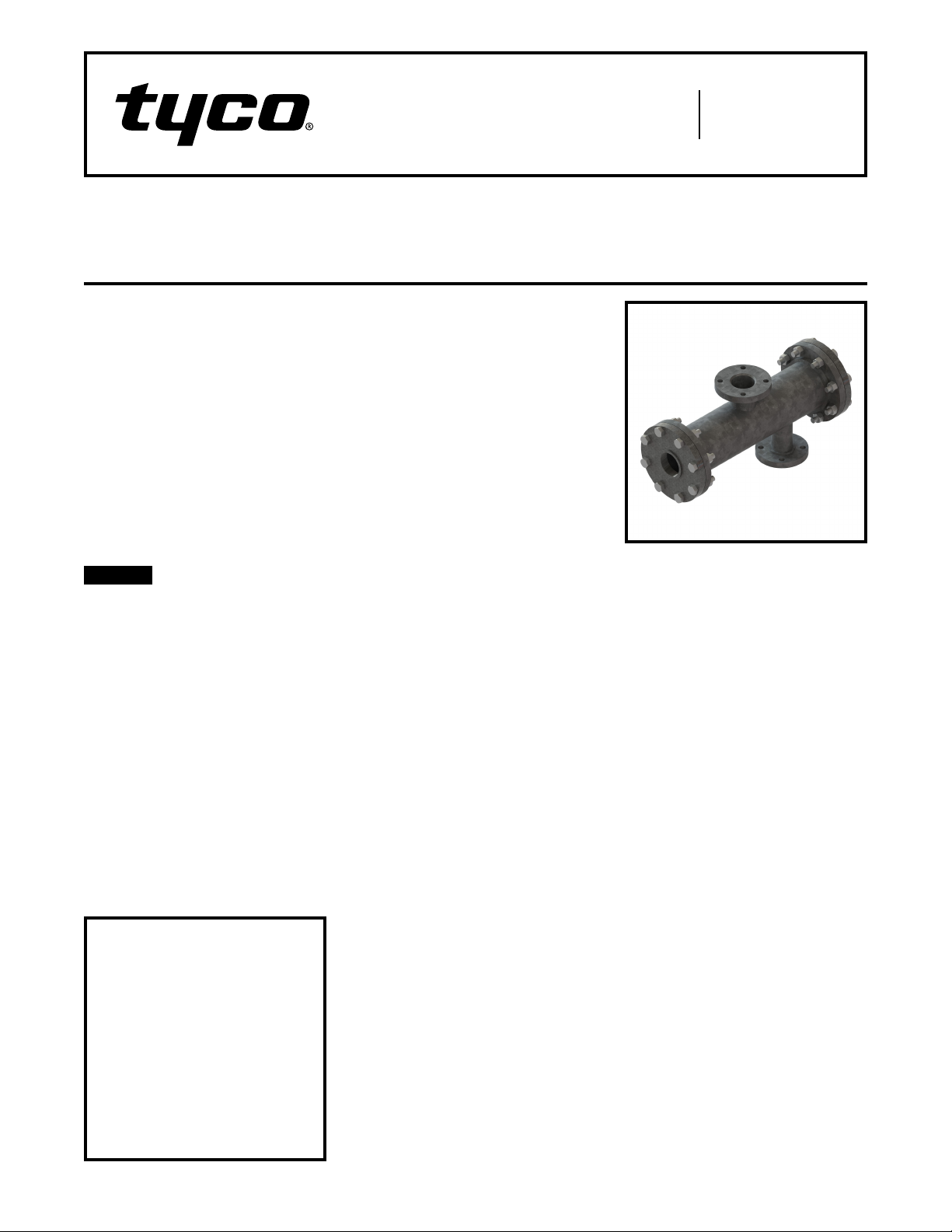
Specify: Standard Model A Pipe Line
Strainer, (specify) Inlet Size, Figure No�
(specify), P/N (specify):
1260-2 ����������������������52-270-1-011
1260-3 ����������������������52-270-1-013
1260-5 ����������������������52-270-1-015
1260-6 ����������������������52-270-1-016
1260-7 ����������������������52-270-1-017
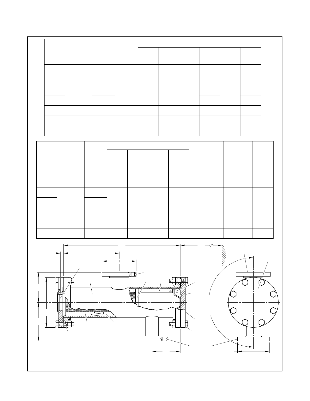
Note: Standard order strainer features
inlet and outlet connections equal in
size, stainless steel basket assembly,
and outlet connection located at Angle
"J" 180° from flushing connection (Ref.
Figure 1). Adjusted outlet connection
available on request, refer to Special
Order Strainers.
Special Order Strainers
Specify: Standard Model A Pipe Line
Strainer, Figure No� (specify), (specify
Stainless Steel or MONEL) Basket
Assembly, (specify) Inlet Size, (specify)
Outlet Size, Outlet Angle "J" (specify
degrees)
Notes: Special order strainer features
any of the following: MONEL basket
assembly; inlet and outlet connec-
tions differing in size; outlet connec-
tion oriented at angle other than the
standard 180° Angle "J" (90° to 270°
counter-clockwise from flushing con-
nection when viewing strainer from end
closure). Ref. Figure 1.
It is recommended that orders for
strainers with special outlet locations
or angles be accompanied by sketches.
Part numbers are not specified for
special order strainers.
Replacement Parts
Specify: (specify inlet size) Model A
Strainer (specify part description),
P/N (specify):
Stainless Steel Basket Assembly
3 Inch �����������������������92-270-1-211
4 Inch �����������������������92-270-1-213
6 Inch �����������������������92-270-1-215
8 Inch �����������������������92-270-1-216
10 Inch ����������������������92-270-1-217
MONEL Basket Assembly
3 Inch �����������������������92-370-3-211
4 Inch �����������������������92-370-3-213
6 Inch �����������������������92-370-3-215
8 Inch �����������������������92-370-3-216
10 Inch ����������������������92-370-3-217
Ring Gasket
3 Inch �����������������������92-370-1-015
4 Inch �����������������������92-370-1-016
6 & 8 Inch ��������������������92-370 -1- 018
10 Inch ����������������������92-370 -1- 020
Note: Ring gaskets are identified per
strainer inlet size. Actual gasket sizes
vary per Body Nominal Pipe Sizes given
in Figure 1.