PreCise WTS-01 User manual

Air & Road Conditions (ARC)
WTS-01 Installation and Operation Manual
Product Description
The PreCise®ARC System, WTS-01, is a wireless sensor designed to provide accurate
road and air conditions information to a remote in-cab display. Easily view and collect
data critical to decision making including relative humidity, dew point, air temperature
and road temperature.
Features
• Air Temp: ±0.5°C (±1.0°F) typical
• Relative Humidity: ±4% typical
• Dew Point/Frost Point: ±2.0°C (±4.0°F) typical
• Road Temp: ±1.0°C (±2.0°F) typical
• Emissivity: calibrated to 0.95
• Field of View: 10°
• Operating Temp: -40°C to 85°C (-40°F to 185°F)
• Communications: IEEE 802.15.4 (2.4GHz DSSS)
• Range: 10m (33ft) typical
• Power: 1.5V alkaline D Cell

PreCise MRM Installation and Operation Manual
WTS-01
1311 East Franklin Road, Suite 102
Meridian, Idaho 83642
www.PreCiseMRM.com
a subsidiary of FORCE America
WTS-01A
Copyright 2017
Support: 1-888-254-1634
Sales: 1-888-449-0357
p. 2 of 8
Warnings & Cautions
•Read and follow all safety rules and instructions before installing or operating this equipment.
•Never operate a vehicle within a closed area. Always assure proper ventilation before starting
engine.
•Always use eye protection. Use goggles that are ANSI approved against impacts and shattering.
•Before wiring, disconnect the negative cable from the battery terminal. Failure to do so may result in
electric shock or injury due to electrical shorts. Batteries can generate explosive gases. Keep sparks,
flames and smoking materials away from batteries. Always wear eye protection around batteries.
•Do not damage pipe or wiring when drilling holes. When drilling holes in the chassis for installation,
take precautions so as not to contact, damage or obstruct pipes, fuel lines, tanks or electrical wiring. Failure
to take such precautions may result in fire.
•Do not use bolts or nuts in the brake or steering systems to make ground connections. Bolts or
nuts used for the brake or steering systems (or any other safety-related system), or tanks should NEVER be
used for installations or ground connections. Using such parts could disable control of the vehicle and cause
fire etc.
•Arrange the wiring so it is not crimped or pinched by a sharp edge. Route the cables and wiring away
from moving parts (like the seat rails) or sharp or pointed edges. This will prevent crimping and damage to
the wiring. If wiring passes through a hole in metal, use a rubber grommet to prevent the wires insulation
from being cut by the metal edge of the hole.
•When making connections to the vehicle's electrical system, be aware of the factory installed components
(e.g. on-board computer). Do not tap into these leads to provide power for this unit. When connecting the
unit to the fuse box, make sure the fuse for the intended circuit has the appropriate amperage. Failure to do
so may result in damage to the unit and/or the vehicle.
•Be sure to connect the color coded leads according to the diagram. Incorrect connections may cause the
unit to malfunction or damage to the vehicle's electrical system.
•To avoid property damage, personal injury, or death, park the vehicle on a flat level surface, set the parking
brake, turn the engine off, and chock the wheels before beginning installation.
•Do not mount the module in a location that could interfere with proper operation of the vehicle, such as
behind the gas or brake pedals.
•Avoid any circuits associated with the airbag system. Inadvertent airbag deployment may cause personal
injury or death.
PreCise MRM Installation and Operation Manual
WTS-01
1311 East Franklin Road, Suite 102
Meridian, Idaho 83642
www.PreCiseMRM.com
a subsidiary of FORCE America
WTS-01A
Copyright 2017
Support: 1-888-254-1634
Sales: 1-888-449-0357
p. 3 of 8
INSTALLATION INSTRUCTIONS
Before You Start
Prior to installing the PreCise®Temperature Sensor and Display, take time to familiarize
yourself with the installation instructions, theory of operation, and system components.
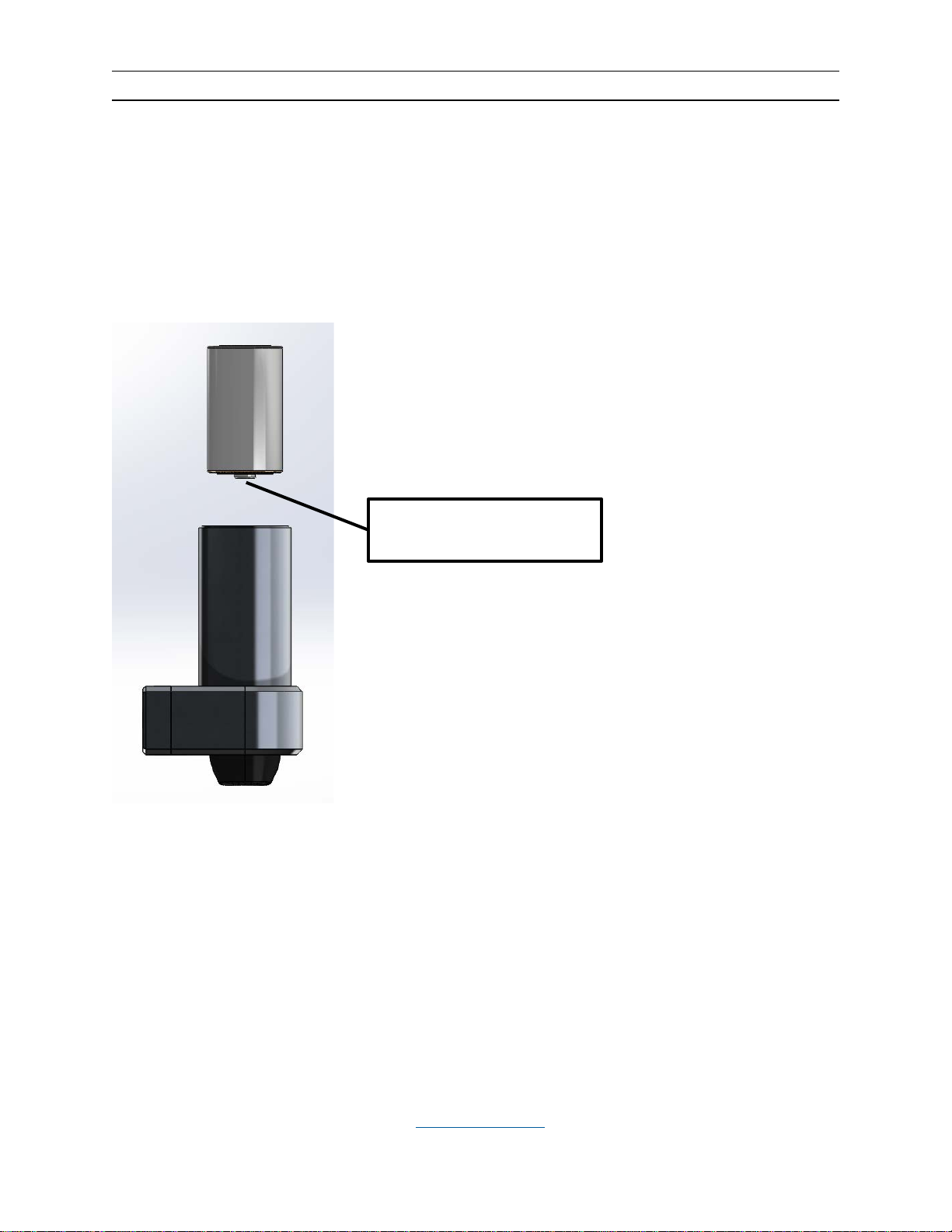
Battery Installation
Install the battery with the positive (+) terminal down. Avoid
dropping the battery in, if possible. Screw the top cap on,
making sure that it is fully seated to provide proper sealing.
To remove the battery without taking the sensor off of the
vehicle, you can use a magnet to retrieve the battery.
Positive (+) Terminal

PreCise MRM Installation and Operation Manual
WTS-01
1311 East Franklin Road, Suite 102
Meridian, Idaho 83642
www.PreCiseMRM.com
a subsidiary of FORCE America
WTS-01A
Copyright 2017
Support: 1-888-254-1634
Sales: 1-888-449-0357
p. 4 of 8
Mounting Locations
Two sets of #10-32 socket-head cap screws are included with the sensor. The #10-
32x3/4” screws are suitable for mounting to tubes between 5/8” and 3/4” in diameter.
The #10-32x1-1/4” screws are suitable for mounting to tubes between 15/16” and 1-1/8”
in diameter. The screws are driven with a 5/32” Allen wrench.
The sensor needs to have good clearance from the ground and no parts of the vehicle
should obstruct the sensor’s field of view. The closer to the ground the sensor is the
smaller the sample area is for road temperature.
The sensor can be mounted at less than 1 foot; though it is not recommended as the
sample size will be small. Also snow, ice, salt, and dirt can be thrown up and cover the
distal end of sensor at that height should they be present on the road. Sensor can be
mounted as high as 8 feet. Figure 1 shows the clearance from the vehicle versus the
height of the sensor above the road surface. It is important to note the higher the sensor
is mounted, the greater distance from the vehicle is needed to ensure the sensor is only
measuring road temperatures, and not a combination of the road and vehicle
temperatures. For every foot of height the width of the area measured widens by
approximately 2.1 inches.
For questions regarding installation or operation, please contact PreCise Support
at 888-254-1634 during normal business hours (7AM-6PM Mountain Time,
Monday-Friday) or support@precisemrm.com.


PreCise MRM Installation and Operation Manual
WTS-01
1311 East Franklin Road, Suite 102
Meridian, Idaho 83642
www.PreCiseMRM.com
a subsidiary of FORCE America
WTS-01A
Copyright 2017
Support: 1-888-254-1634
Sales: 1-888-449-0357
p. 6 of 8
WTS-01 Specifications
Sensors
Parameter
Rating
Units
Air Temperature
±0.5
°C (typ)
±1.0
°F (typ)
Air Temperature Response Time (1)
30
Minutes (typ)
Relative Humidity
±4
% (typ)
Relative Humidity Response Time (1)
30
Minutes (typ)
Road Temperature
±1.0
°C (typ)
±2.0
°F (typ)
Road Temperature Response Time
1
Second (typ)
Emissivity
0.95
Field of View
10
°
Notes: (1) when vehicle is moving > 5mph
802.15.4 Radio
Parameter
Rating
Units
Range
33
ft (typ)
10
m (typ)
Radio type
IEEE 802.15.4
Frequency
coverage
2.405-2.480
GHz
RF Sensitivity
-94
dBm (typ)
Maximum RF
Input
+5
dBm (min)
Transmitter
Power output
0
dBm (typ)
FCC Part 15
ETSI 300/328
FCC ID: OA3MRF24J40MA
IC: 7693A-24J40MA
Power
Parameter
Rating
Units
Supply voltage
Operating
0.8 to 1.6
Vdc
Supply current (Battery Voltage = 1.5V, 25°C ambient)
Report Interval (s)
2
3.2
mA (typ)
10
0.9
mA (typ)
30
0.5
mA (typ)
sleep
0.3
mA (typ)

PreCise MRM Installation and Operation Manual
WTS-01
1311 East Franklin Road, Suite 102
Meridian, Idaho 83642
www.PreCiseMRM.com
a subsidiary of FORCE America
WTS-01A
Copyright 2017
Support: 1-888-254-1634
Sales: 1-888-449-0357
p. 7 of 8
Physical
Parameter
Rating
Units
Dimensions
5.1 x 2.9 x 2.1
in
130 x 74 x 54
mm
Weight
1.1
lbs
0.5
kg
Environmental
Parameter
Rating
Operating Temperature
-40°C to +85°C
Storage Temperature
-40°C to +85°C
Humidity
0% to 100% RH at +40°C
Ingress Protection
IPX9K – High Pressure Steam
Vibration
MIL-STD 810G (7.7g, 20Hz-2kHz).
Shock
±30g

PreCise MRM Installation and Operation Manual
WTS-01
1311 East Franklin Road, Suite 102
Meridian, Idaho 83642
www.PreCiseMRM.com
a subsidiary of FORCE America
WTS-01A
Copyright 2017
Support: 1-888-254-1634
Sales: 1-888-449-0357
p. 8 of 8
MANUFACTURER LIMITED WARRANTY AND LIMITATION OF LIABILITY
Manufacturer warrants that on the Date of Purchase this Product will conform to Manufacturer's published
specifications for the product, which are available from Manufacturer on request, and Manufacturer
warrants that the product is free from defects in materials and workmanship. This Limited Warranty extends
for twelve (12) months from the date of delivery. Manufacturer will, at its option, repair or replace any
product found by Manufacturer to be defective and subject to this Limited Warranty.
This Limited Warranty does not apply to parts or products that are misused; abused; modified; damaged by
accident, fire or other hazard; improperly installed or operated; or not maintained in accordance with the
maintenance procedures set forth in Manufacturer's Installation and Operating Instructions.
To obtain warranty service, you must ship the product(s) to the specified Manufacturer location within thirty
(30) days from expiration of the warranty period. Contact customer service to obtain a RMA number and
write the number on the shipping container. You must prepay shipping charges and use the original
shipping container or equivalent. Return shipping charges within the United States, Canada, and Puerto
Rico, will be paid by Manufacturer. This Limited Warranty will apply only to a product purchased and
located in the United States, Canada, or Puerto Rico.
EXCLUSION OF OTHER WARRANTIES: MANUFACTURER MAKES NO OTHER WARRANTIES,
EXPRESSED, IMPLIED OR STATUTORY. THE IMPLIED WARRANTIES FOR MERCHANTABILITY AND
FITNESS FOR A PARTICULAR PURPOSE ARE HEREBY EXCLUDED AND SHALL NOT APPLY TO
THE PRODUCT. BUYER'S SOLE AND EXCLUSIVE REMEDY IN CONTRACT, TORT OR UNDER ANY
OTHER THEORY AGAINST MANUFACTURER RESPECTING THE PRODUCT AND ITS USE SHALL BE
THE REPLACEMENT OR REPAIR OF THE PRODUCT AS DESCRIBED ABOVE.
LIMITATION OF LIABILITY:IN THE EVENT OF LIABILITY FOR DAMAGES ARISING OUT OF THIS
LIMITED WARRANTY OR ANY OTHER CLAIM RELATED TO MANUFACTURER'S PRODUCTS,
MANUFACTURER'S LIABILITY FOR DAMAGES SHALL BE LIMITED TO THE AMOUNT PAID FOR THE
PRODUCT AT THE TIME OF ORIGINAL PURCHASE. IN NO EVENT SHALL MANUFACTURER BE
LIABLE FOR LOST PROFITS, THE COST OF SUBSTITUTE EQUIPMENT OR LABOR, PROPERTY
DAMAGE, OR OTHER SPECIAL, CONSEQUENTIAL OR INCIDENTAL DAMAGES BASED UPON ANY
CLAIM FOR BREACH OF CONTRACT, NEGLIGENCE OR OTHER CLAIM, EVEN IF MANUFACTURER
OR A MANUFACTURER'S REPRESENTATIVE HAS BEEN ADVISED OF THE POSSIBILITY OF SUCH
DAMAGES. Manufacturer shall have no further obligation or liability with respect to the product or its sale,
operation and use, and Manufacturer neither assumes nor authorizes the assumption of any other
obligation or liability in connection with such product.
This Limited Warranty gives you specific legal rights, and you may also have other legal rights, which vary,
from state to state. Some states do not allow the exclusion or limitation of incidental or consequential
damages, so the above exclusion or limitation may not apply to you.
Any oral statements or representations about the product, which may have been made by salesmen or
Manufacturer representatives, do not constitute warranties. This Limited Warranty may not be amended,
modified or enlarged, except by a written agreement signed by an authorized official of Manufacturer that
expressly refers to this Limited Warranty.
Part 15 Notice:
This device complies with Part 15 of the FCC rules. Operation is subject to the following two conditions: (1) This device may not
cause harmful interference, and (2) this device must accept any interference received, including interference that may cause
undesired operation.
Table of contents
Other PreCise Accessories manuals

Popular Accessories manuals by other brands

GSI Outdoors
GSI Outdoors PNEG-214 installation manual

NuAire
NuAire MRXBOX95-PIR Installation and Maintenance

Venture Measurement
Venture Measurement Genuine Bindicator VRF-2000 Series quick start guide

SEVERIN
SEVERIN TURBOBÜRSTE TB 9070 Dimensions

Omron
Omron D6T Series user manual

SICK
SICK GLS611 operating instructions


