manuals.online logo
Brands
  1. Home
  2. •
  3. Brands
  4. •
  5. NuAire
  6. •
  7. Accessories
  8. •
  9. NuAire MRXBOX95-PIR Instruction Manual

NuAire MRXBOX95-PIR Instruction Manual

1
nuaire.co.uk 029 2085 8400 08. 04. 19. Document Number 671445
The EMC Directive
2014/30/EU
The Low Voltage
Directive
2014/35/EU
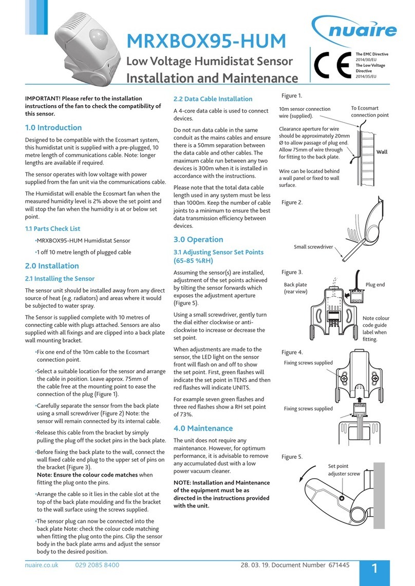
MRXBOX95-PIR
Passive InfraRed Low Voltage Sensor
Installation and Maintenance
IMPORTANT! Please refer to the installation
instructions of the fan to check the compatibility of
this sensor.
1.0 Introduction
Designed to be compatible with the Ecosmart system,
this PIR unit is supplied with a pre-plugged, 10 metre
length of communications cable. Note: longer lengths
are available if required.
The sensor operates with low voltage with power
supplied from the fan unit via the communications cable.
The PIR sensor will activate the system when movement
is detected. An adjustable 1-60 minute timer is
incorporated to provide a run on facility.
1.1 Parts Check List
•MRXBOX95-PIR Passive InfraRed Occupancy Sensor
•1 off 10 metre length of plugged cable
2.0 Installation
2.1 Installing the Sensor
The sensor unit should be installed away from any direct
source of heat (e.g. radiators) and areas where it would
be subjected to water spray. The Sensor is supplied
complete with
10 metres of connecting cable with plugs attached.
Sensors are also supplied with all fixings and are clipped
into a back plate wall mounting bracket.
•Fix one end of the 10m cable to the Ecosmart
connection point.
•Select a suitable location for the sensor and arrange
the cable in position. Leave approx. 75mm of
the cable free at the mounting point to ease the
connection of the plug (Figure 1).
•Carefully separate the sensor from the back plate
using a small screwdriver (Figure 2). Note: the
sensor will remain connected by its internal cable.
•Release this cable from the bracket by simply
pulling the plug off the socket pins in the back plate.
•Before fixing the back plate to the wall, connect the
wall fixed cable end plug to the upper set of pins on
the bracket (Figure 3).
Note: Ensure the colour code matches when
fitting the plug onto the pins.
Arrange the cable so it lies in the cable slot at the
top of the back plate moulding and fix the bracket
to the wall surface using the screws supplied.
•The sensor plug can now be connected into the
back plate Note: check the colour code matching
when fitting the plug onto the pins.
2.2 Data Cable Installation
A 4-core data cable is used to connect
devices.
Do not run data cable in the same
conduit as the mains cables and ensure
there is a 50mm separation between
the data cable and other cables. The
maximum cable run between any two
devices is 300m when it is installed in
accordance with the instructions.
Please note that the total data cable
length used in any system must be less
than 1000m. Keep the number of cable
joints to a minimum to ensure the best
data transmission efficiency between
devices.
3.0 Operation
3.1 Adjusting Run On Timer
(1-60 minutes)
Assuming the sensor(s) are installed,
adjustment of the set points achieved
by tilting the sensor forwards which
exposes the adjustment aperture
(Figure 5).
Using a small screwdriver, gently turn
the dial either clockwise or anti-
clockwise to increase or decrease the
set point.
When adjustments are made to the
sensor, the LED light on the sensor
front will flash on and off to show
the set point. First, green flashes will
indicate the set point in TENS, followed
by red flashes which indicate UNITS.
For example one green flash and five
red flashes show you that the PIR timer
is set to fifteen minutes.
3.2 Detection range
The detection range of this sensor is up
to 10m directly in front of lens and up
to 2m at 40° to the lens axis.
4.0 Maintenance
The unit does not require any
maintenance. However, for optimum
performance, it is advisable to remove
any accumulated dust with a low
power vacuum cleaner.
NOTE: Installation and Maintenance
of the equipment must be as
directed in the instructions provided
with the unit.
Figure 1.
Figure 2.
Figure 3.
Figure 4.
Figure 5.
Fixing screws supplied
Set point
adjuster screw
10m sensor connection
wire (supplied).
To Ecosmart
connection point
Clearance aperture for wire
should be approximately 20mm
Ø to allow passage of plug end.
Allow 75mm of wire through
for fitting to the back plate.
Wire can be located behind
a wall panel or fixed to wall
surface.
Small screwdriver
Back plate
(rear view)
Plug end
Note colour
code guide
label when
fitting.
Wall

2
nuaire.co.uk 029 2085 8400 08. 04. 19. Document Number 671445
Installation and Maintenance MRXBOX95-PIR
5.0 Warranty
The 5 year warranty starts from the day of delivery and includes parts
and labour for the first year. The remaining 4 years covers replacement
parts only.
This warranty is void if the equipment is modified without
authorisation, is incorrectly applied, misused, disassembled, or not
installed, commissioned and maintained in accordance with the details
contained in this manual and general good practice.
The product warranty applies to the UK mainland and in accordance
with Clause 14 of our Conditions of Sale.
Customers purchasing from outside of the UK should contact Nuaire
International Sales office for further details.
6.0 After Sales Enquiries
For technical assistance or further product information, including spare
parts and replacement components, please contact the After Sales
Department.
Telephone 02920 858 400
aftersales@nuaire.co.uk

Other NuAire Accessories manuals

NuAire DRI-ECO-CO2 User manual

NuAire

NuAire DRI-ECO-CO2 User manual

NuAire NU-1000 User manual

NuAire

NuAire NU-1000 User manual

NuAire 3 Series User manual

NuAire

NuAire 3 Series User manual

NuAire NU-8625 User manual

NuAire

NuAire NU-8625 User manual

NuAire Ecosmart Connect ESCO-CO2D Instruction Manual

NuAire

NuAire Ecosmart Connect ESCO-CO2D Instruction Manual

NuAire 12 Series User manual

NuAire

NuAire 12 Series User manual

NuAire DRI-ECO-RH User manual

NuAire

NuAire DRI-ECO-RH User manual

NuAire MRXBOX95-HUM Instruction Manual

NuAire

NuAire MRXBOX95-HUM Instruction Manual

NuAire NU 4500 User manual

NuAire

NuAire NU 4500 User manual

NuAire NU-5500 User manual

NuAire

NuAire NU-5500 User manual

NuAire NU-8600 User manual

NuAire

NuAire NU-8600 User manual

NuAire CM-XBOX-INLINE Instruction Manual

NuAire

NuAire CM-XBOX-INLINE Instruction Manual

NuAire ES-PIR2 User manual

NuAire

NuAire ES-PIR2 User manual

NuAire ESCO-CO2D User manual

NuAire

NuAire ESCO-CO2D User manual

NuAire ES-RH User manual

NuAire

NuAire ES-RH User manual

NuAire NU-5510 User manual

NuAire

NuAire NU-5510 User manual

NuAire ES-TEMP2 User manual

NuAire

NuAire ES-TEMP2 User manual

NuAire NU-5810 User manual

NuAire

NuAire NU-5810 User manual

NuAire 7 Series User manual

NuAire

NuAire 7 Series User manual

NuAire NU-5710 User manual

NuAire

NuAire NU-5710 User manual

NuAire 1 Series User manual

NuAire

NuAire 1 Series User manual

NuAire 5 Series User manual

NuAire

NuAire 5 Series User manual

Popular Accessories manuals by other brands

Ingics iBS05 user guide

Ingics

Ingics iBS05 user guide

Orno OR-AE-1342 quick start guide

Orno

Orno OR-AE-1342 quick start guide

Campbell HFP01 product manual

Campbell

Campbell HFP01 product manual

Audient iD14 user manual

Audient

Audient iD14 user manual

Pelican PLUS50 installation guide

Pelican

Pelican PLUS50 installation guide

Zamel ynsta PDK-250/2 manual

Zamel

Zamel ynsta PDK-250/2 manual

PCB Piezotronics 116B Installation and operating manual

PCB Piezotronics

PCB Piezotronics 116B Installation and operating manual

BONA SPES VIKING E16W Instructions for use

BONA SPES

BONA SPES VIKING E16W Instructions for use

DYNATEK DVM-1 User instructions

DYNATEK

DYNATEK DVM-1 User instructions

schmersal BNS 36 AS operating instructions

schmersal

schmersal BNS 36 AS operating instructions

Peavey DPM SP supplementary guide

Peavey

Peavey DPM SP supplementary guide

Pyronix CHIME Getting started

Pyronix

Pyronix CHIME Getting started

Intenso PM5200 user manual

Intenso

Intenso PM5200 user manual

RME Audio ADI-648 user guide

RME Audio

RME Audio ADI-648 user guide

Montiss DELUXE user manual

Montiss

Montiss DELUXE user manual

Stack TPMS Lite installation guide

Stack

Stack TPMS Lite installation guide

S+S Regeltechnik HYGRASREG KH-30 Operating Instructions, Mounting & Installation

S+S Regeltechnik

S+S Regeltechnik HYGRASREG KH-30 Operating Instructions, Mounting & Installation

Ideal Vacuum XactGauge XGC-321 operating manual

Ideal Vacuum

Ideal Vacuum XactGauge XGC-321 operating manual

manuals.online logo
manuals.online logoBrands
  • About & Mission
  • Contact us
  • Privacy Policy
  • Terms and Conditions

Copyright 2025 Manuals.Online. All Rights Reserved.