1 General safety notes
■Read these operating instructions before commissioning the device.
■
Connection, mounting and configuration of the device must only be carried
out by qualified personnel.
■
This device does not constitute a safety component as defined in the
Machinery Directive.
■
When commissioning the device, ensure adequate protection against mois‐
ture, contamination and UV radiation (sunlight).
■These operating instructions contain information required during the life cycle of
the photoelectric sensor.
2 Notes on UL approval
The device shall be supplied from an isolating transformer having a secondary overcur‐
rent protective device that complies with UL 248 to be installed in the field rated either:
a) max 5 amps for voltages 0 ~ 20 V (0 ~ 28.3 V peak), or
b) 100 / Vp for voltages of 20 ~ 30 V (28.3 ~ 42.4 V peak).
Alternatively, they can be supplied from a Class 2 power supply.
UL Environmental Rating: Enclosure type 1
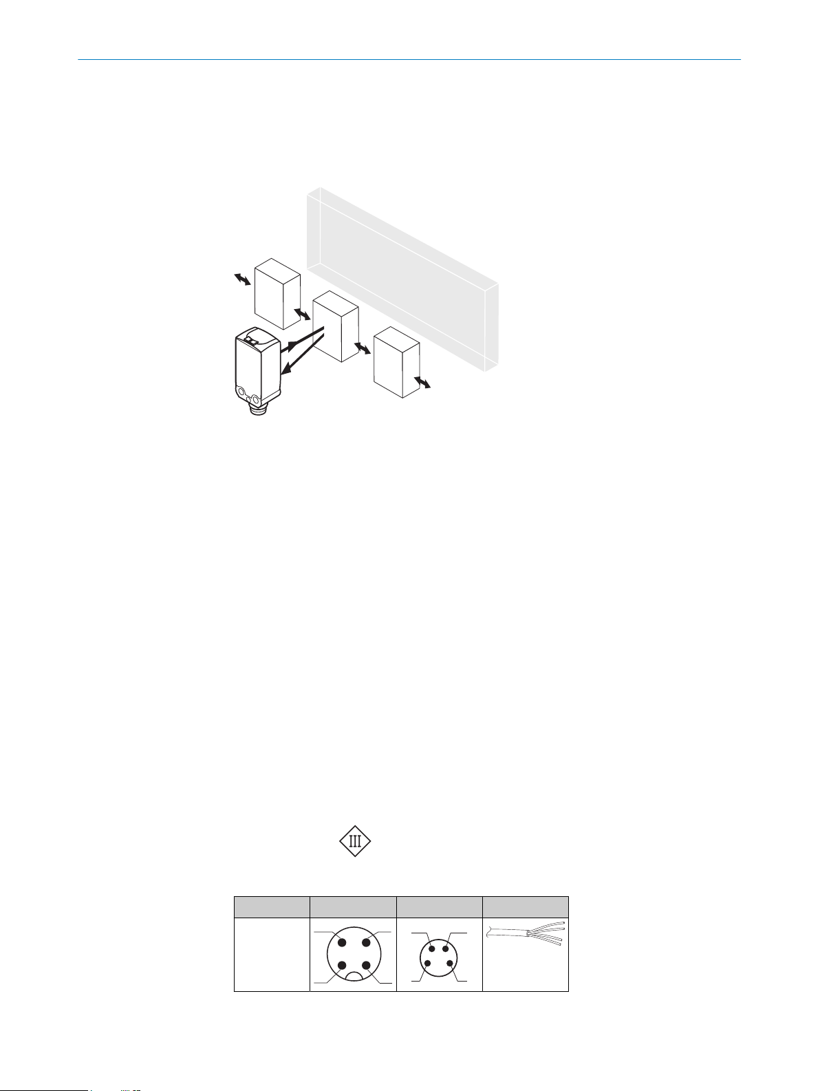
3 Intended use
The WTB4FP MultiSwitch is an opto-electronic photoelectric background suppression
proximity sensor (referred to as “sensor” in the following) for the optical, non-contact
detection of objects, animals, and persons. If the product is used for any other purpose
or modified in any way, any warranty claim against SICK AG shall become void.
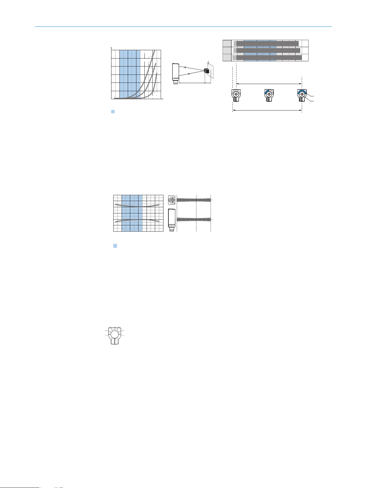
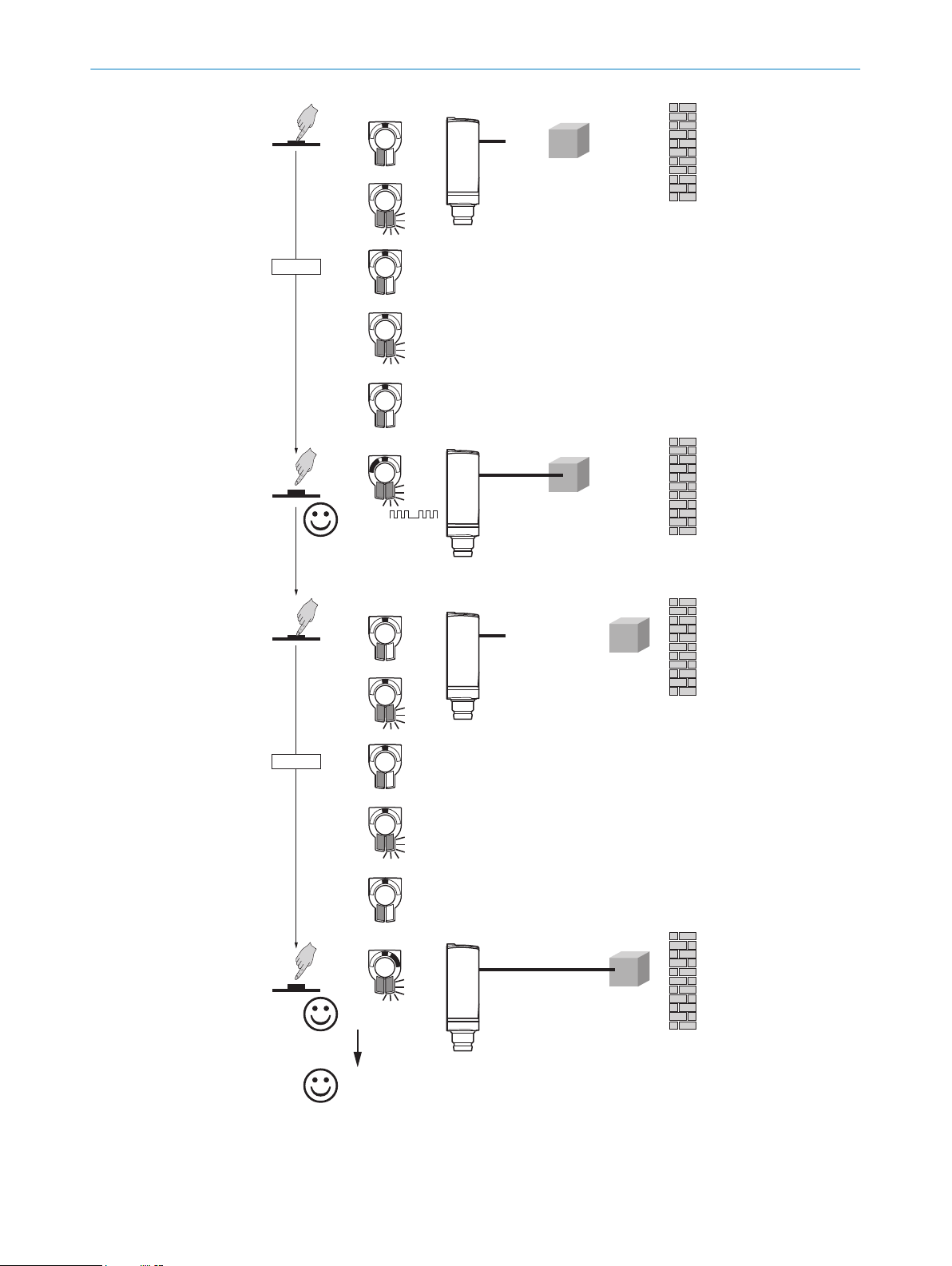
4 Operating elements and status indicators
Photoelectric proximity sensor with background suppression.
1BluePilot blue: operating mode, Switching state QL1, QL2
2Teach-Button: adjusting the sensing range
3LED indicator yellow: status of received light beam
4LED indicator green: supply voltage active
GENERAL SAFETY NOTES 1
8025665 / 2020-11-13 | SICK
Subject to change without notice 5