Precision Digital Corporation PD6620 Series User manual
Precision Digital corPoration
www.predig.com
2
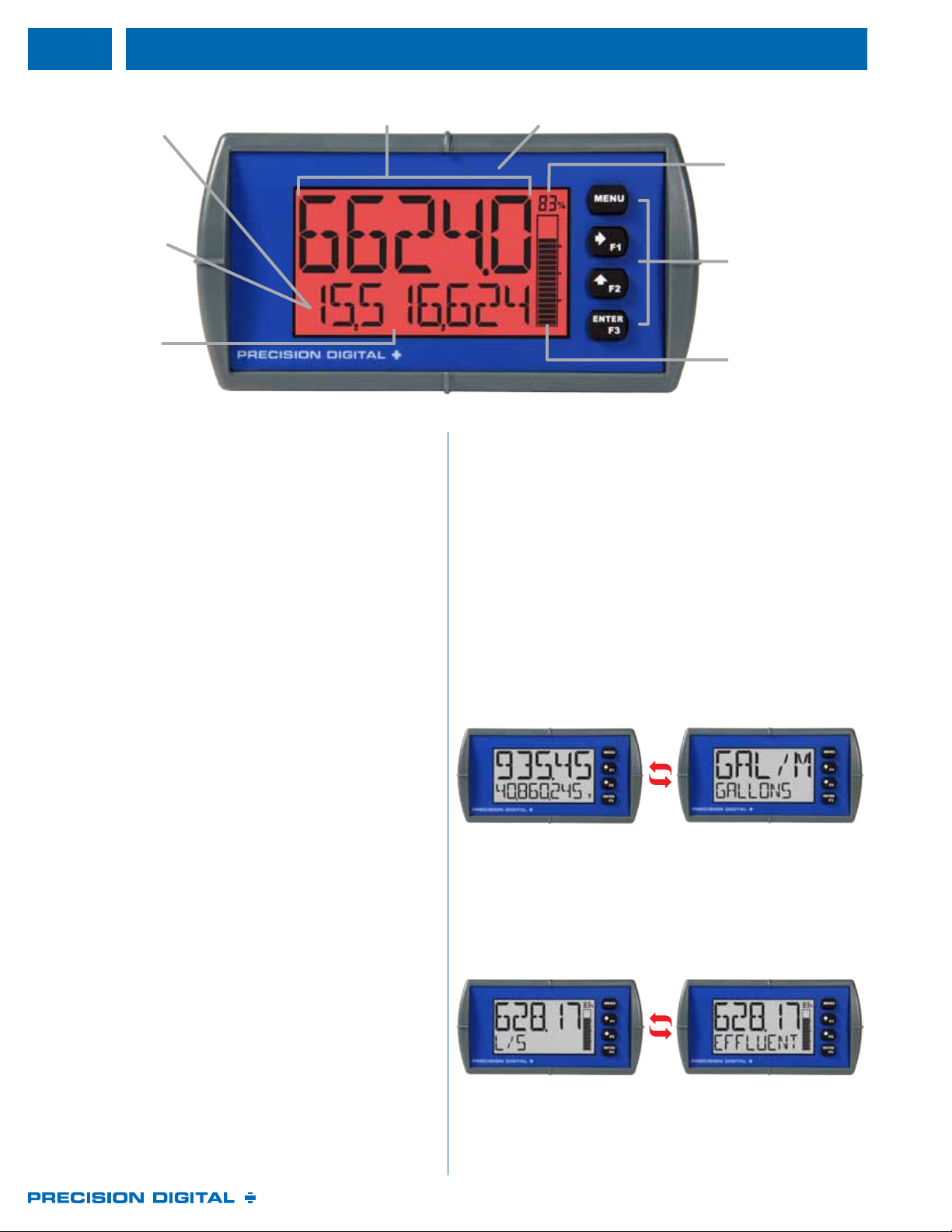
Five (5) 0.7" Large Digits
on Top Line for Rate
Showing Red
Backlight for
Alarm Indication
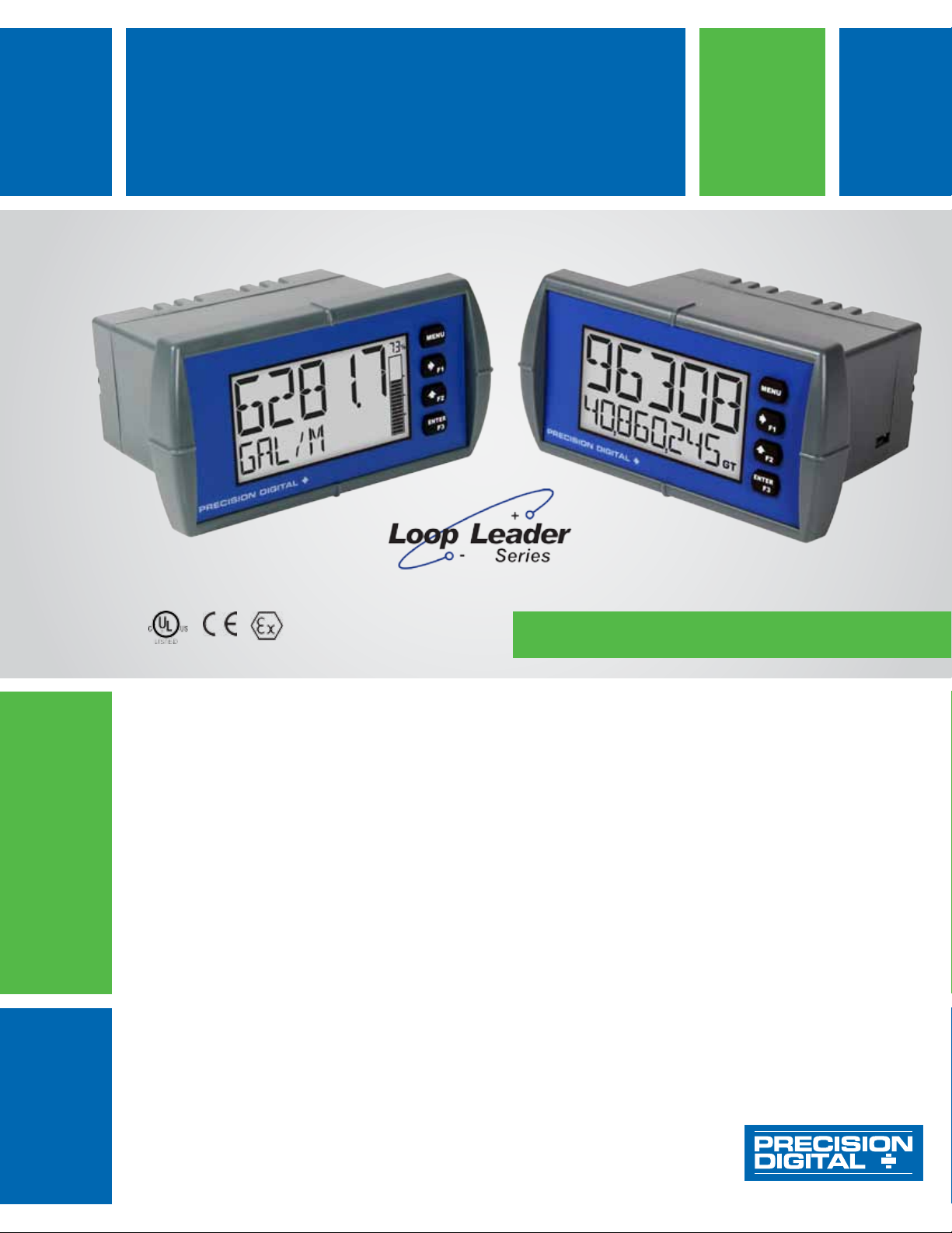
These loop-powered 1/8 DIN flow rate/totalizers can be installed
virtually anywhere to provide convenient and informative display
of flow rate and total from a 4-20 mA signal. One of the most
convenient features of these instruments is their ability to display
both flow rate and total at the same time. For instance, flow rate
is typically displayed on the 5-digit alphanumeric top line and flow
total or grand total is typically displayed on the 8-digit alphanumeric
bottom line.
Both of these lines use 14-segment, alphanumeric characters for
clear indication of tags, units or alarm messages.
Further enhancing the display on these instruments is a 20-segment
bargraph available on the PD6624/8 that also includes a numeric
value of the percentage the bargraph represents.
These flow rate/totalizers can be installed virtually anywhere
because they get their power from the 4-20 mA loop and therefore
require no separate power source. And they only drop 1.5 V
(4.7 V with backlight), so they add very little burden to the loop.
Additional features that allow these instruments to be installed
virtually anywhere include a NEMA 4X, IP65 front panel, an
operating temperature range of -40 to 167°F (-40 to 75°C) (for safe
area products), conformally coated PCBs, and a backlit LCD that
can be read in bright sunlight or dimly lit areas. Finally, there are
intrinsically safe and nonincendive versions of these instruments
that can be installed in hazardous areas.
Free, PC-based, software that connects to the meter via a micro
USB cable is available for programming and setup of the meters.
In addition, the meter can be programmed, setup and operated
via the four front panel buttons. Three of these buttons can be
used as function keys. In addition, a digital input is standard and
is particularly useful for remote reset of the total or to start/stop a
timer/batch.
All models come equipped with two open collector outputs and are
available with two solid state relays and 4-20 mA analog output
options. The open collector outputs are useful for alarm indication or
sending a pulse to indicate when a certain amount of total has been
accumulated. The relays can be programmed for alarm indication,
on/off control, sample taking, or simple batch control.
Bargraph Numeric
Percent Indication
Front Panel
Buttons for Setup,
Programming, and
Operation
Bargraph for Visual
Representation
of Rate or Total
Percentage
NEMA 4X,
IP65 Front
▲ PD6624/28 with Bargraph Shown
The Loop Leader’s display provides multiple ways to help users
understand and keep track of their processes. The most obvious is
the dual line which typically allows the user to display both flow rate
and total at the same time. There is also a bargraph that includes a
numeric value of the percentage the bargraph represents. Finally,
to alert users to an alarm condition, the display can turn red and
flash an alarm message.
One of the key features of the Loop Leader Flow Rate/Totalizers
is their ability to display flow rate and total at the same time. In
addition, the meter can toggle between the rate and total and their
corresponding units as the following illustrates:
8-Digit
Alphanumeric
Bottom Line for
Total, Grand Total,
and Predened or
Custom Units
In addition to the most common setup of flow rate on the top line
and flow total on the bottom line, these meters can be set up for a
variety of display configurations.
8-Digit Total
includes Commas
for Easier Reading

www.predig.com
3
BOTTOM
O (Blank) Units for value on top line
Total (with units or tag alternating) Tag
Total, its units, and the rate and
units alternating
Preset batch value
Grand total (with units or tag
alternating)
Tag and rate units alternating
Grand total, units, and rate units
alternating
Tag and total units alternating
Rate (with units or tag alternating) Rate’s percentage of max scale
Rate and the total’s units
alternating
mA input value
Rate or total units mA output value
The following table shows the items that can be displayed on the
Top and Bottom lines:
To help users get a quick understanding of where their process is
at, certain Loop Leader models are available with a 20-segment
bargraph. This bargraph also includes a numeric value of the
percentage the bargraph represents. The bargraph can be
programmed to represent either the rate or total or it can be disabled.
When an alarm occurs, the Loop Leader’s display can be
programmed to turn red and flash an alarm message along with
the process variable and an alarm indicator (!). (Alarm indicator
symbols are not available on bargraph models) The Loop Leader’s
flashing red alarm message can be activated even if no relay or
open collector is connected.
Users can use the Loop Leader’s dual-scale feature when they
want to show the same input in two different scales. For instance,
the following example shows an application where the Loop Leader
displays the input in gallons per minute and cubic feet per minute:
The max & min readings (peak & valley) reached by the process can
be displayed either continuously or momentarily:
1. Display momentarily by pressing the F1 key (default) or assigning
to any of the other function keys or to the digital input in the User
menu. Press Enter to lock/unlock max/min display.
2. Display continuously by assigning either display line to max/min
through the Display menu.
Any of the F1-F3 function keys (buttons) and the digital input can be
programmed to reset the max & min readings.
(note different units than Total)
It may seem like a simple thing, but adding commas to an eight-digit
number makes it easier to read:
TOp
O (Blank) Preset batch value
Rate Stopwatch
Rate and its units alternating Timers OC and relays
Total Min
Total and its units alternating Max
Tag Min & max
Units

www.predig.com
4
The meter has six available preprogrammed unit classes, volume,
height,temperature,pressure,weight, and rate. When the desired
unit class or unit of measure within a class is not available, a custom
unit may be programmed by using the (CUSTOM) menu.
It is possible to change the display units within the selected unit class
without the need to re-scale the meter. When selecting a new unit
from within the DISPLAY menu (e.g. changing from gallons (GAL) to
liters (L)), the meter will automatically convert the display values to
display the new unit. If entering a custom unit (CUSTM), a custom
conversion factor will need to be entered.
Loop Leaders are available with two open collector outputs as
standard and two solid state relays and 4-20 mA output as options.
The open collector outputs and relays generally operate in the
same manner, with the major exception being the open collectors
are not available for batch control or sampling and the relays are
not available with pulse features. The open collectors and relays
can be controlled either automatically or manually. The alarm status
(with flashing red message) will show on the display even with no
output wired.
The Loop Leader is equipped with two NPN open collector outputs
that may be set up for pulse outputs, alarms, timed pulses, stopwatch
on/off, or disabled. Pulse outputs can be set to transmit the rate, total
or grand total. Output 2 may be used to generate a quadrature output
based on the other open collector output. An output test mode is also
selectable to generate pulses at a constant programmable frequency.
The open collectors are commonly used to generate a pulse for every
user-defined amount of flow that has been generated. For instance,
the Loop Leader can be programmed to generate a pulse for every
100 gallons of flow.
The meter is optionally equipped with two solid state relays that may be
set up for alarms, timer, stopwatch on/off, sample or batch control. The
relays are rated at 250 VAC/DC @ 1 A for resistive loads and 75 VA @
0.6 A, 250 VAC/DC max (Safe Area only) for inductive loads. Alarms
are available based on the rate, total, grand total, or digital input.
The open collectors and relays (alarms) may be programmed to reset
in the following ways:
• (AUTO): Alarm will reset automatically once the alarm
condition has cleared.
• (AUTO.MAN): Alarm will reset automatically
once the alarm condition has cleared but can also be reset using
the Enter button (or whichever function key is set to acknowledge)
at any time.
• (LATCH): Alarm must be reset manually and can be
done so at any time. Press the Enter (ACK) button at any time to
clear the alarm.
• (L-CLEAR): Alarm must be
reset manually and can only be done so after the alarm condition
has cleared. Press the Enter (ACK) button after the alarm
condition has cleared to reset the alarm.
Application Timers are used in everyday life; one of the most common
examples is the microwave oven. Industrial timers are used in
process control applications where certain events or actions need to
be controlled by time. Examples include automatic and batch control
applications, where the relay needs to be energized for a specific
length of time.
The timer fuction is available on the open collector and relay outputs;
which means that you can have up to four timers per meter. The start
and stop actions can be triggered from the setup menu or by the
function keys and digital input. The meter can be setup to display the
off/on timer count down.
There are two modes of operation:
At the start of the timer the output is off and turns on after the
Off Delay elapses. The output remains on for the duration of the
On Time. The cycle repeats until the user stops the timer either
from the menu or a function key.
At the start of the timer the output is off and turns on after the
Off Delay elapses. The output remains on for the duration of the
On Time. The timer stops and the cycle does not repeat.
A sensor detects the bottle is in place and triggers the digital
input to start the timer
The timer output controls the filling pump
The On Time is set according to the time needed to fill the bottle
The isolated analog output signal can be configured to represent
the rate, total or to retransmit the 4-20 mA signal input without the
need to scale the output. While the output is nominally 4-20 mA, the
signal will accurately accommodate under- and over-ranges from 1
to 23 mA. The output can be reverse scaled such that the meter’s
high calibration value outputs 4 mA and the meter’s low calibration
outputs 20 mA.
A relay set to sample will trigger when the total or grand total value
has incremented by a programmed amount. The relay can be
programmed to stay on for a specified amount of time. For example:
if a relay is set to sample the total with a COUNT of 1,000 and a TIME
of 10 seconds, the relay will energize for 10 seconds each time the
total increments by 1,000 (e.g. 1000, 2000, 3000).

www.predig.com
5
The Loop Leader, when ordered with the two solid state relays, can be used as a simple, one or two-stage batch controller. The user enters
a preset and preclose value and sets the Loop Leader to either count up or count down. The top display will show the total and the bottom
display will show the preset batch amount. The function keys are automatically changed so that starts a batch, opens the preset menu
to allow the preset value to be changed, and pauses/stops the currently running batch. Batching can be either automatic or manual.
The following shows the Loop Leader performing a manual batch operation:
The is pressed. Both valves open.
The barrel begins to fill.
When the batch total reaches a value of 50.00 (Preset [55.00]
– Preclose [5.00]) the full-flow valve closes. The fill rate of the
tank slows as a result.
When the batch total equals the preset amount, the restricted-
flow valve closes. The barrel is now full.
After placing a new, empty barrel, a new preset fill amount
may be selected with the , while the process
is stopped.
Press the and a new batch will begin.
With both valves open, the process continues.
At any time, the may be pressed, once to
Pause the process, or twice to cancel the batch, which stops
the process.
Both valves are closed with an empty barrel in place. The
batched total is displayed in the top display, the preset is
selected for the bottom display.
The PD6626 and PD6628 are intrinsically safe batch controllers.
www.predig.com
6
Loop Leader flow rate/totalizers can be programmed for a wide
variety of totalizer applications. They can display total, grand total, or
non-resettable grand total; the rate can be displayed with a time base
of seconds, minutes, hours or days. The user can program a totalizer
conversion factor, a non-resettable grand total, password protection,
and several total reset methods.
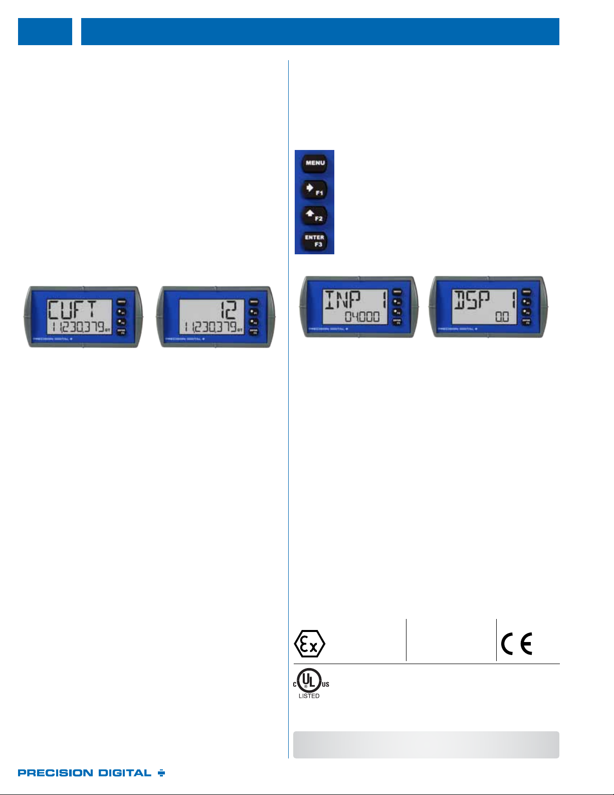
The Loop Leader flow rate/totalizer can be programmed to show
eight full digits of total on the bottom display or 13 digits of total using
both the top and bottom displays. In both cases, the display can be
programmed to include commas to make it easier to read the very
large numbers; ie 44,987,356
In 13-digit mode, the bottom line shows the least significant digits
and the top line shows the most significant digits. The meter is not
capable of displaying commas on the top line, so this number is
actually 1,211,230,379. The comas can be removed from bottom if
desired. See sample on bottom, right.
The user can enter a totalizer conversion factor that allows the
meter to display total in different units than the rate. For instance, a
customer could measure flow rate in gallons per minute and total in
hundredths of acre-feet. A multiplier may be selected to automatically
display the value in kGAL, MGAL, etc.
The total and grand total can be password protected so they can be
reset only by authorized personnel.
The user can set up the grand total to be non-resettable by selecting
YES for PERMLOCK in the Advanced - Grand Total - Reset menu.
Once this is done, the grand total can never be reset.
The total can be reset via an external contact closure on the digital
input.
The three front panel function keys can be programmed to reset
the total and grand total. This makes it possible for the user to reset
either the total or the grand total by pressing the appropriate function
key. Of course, if the total or grand total is password protected, they
will not reset when the function key is pressed unless the password
is entered.
The user may program the meter for a low-flow cutoff such that the
meter displays zero below this point, regardless of the input value.
The Loop Leader’s two relays can be set up to alarm when the
total reaches a user-defined set point. A variety of reset modes are
available and the user can also program time delays and fail-safe
operation.
Meters are set up at the factory for linear function with 2-point
linearization. Up to 32 linearization points can be selected for the
scaled value under the linear function. Multi-point linearization can
be used to linearize the display for non-linear signals to convert
level to flow using weirs and flumes with complex exponent.
A password can be set for programming security to prevent
unauthorized changes to the programmed parameter settings. There
are three password types available: Main, Total, and Grand Total.
The Main password prevents access to the meter Programming
Mode. Total and Grand Total passwords prevent resetting the total
and grand total, respectively.
Loop Leaders can be programmed and setup either by using the
front panel buttons or free, PC-based software with USB interface.
Loop Leader process meters include four front panel buttons for
setup and programming. The front panel buttons along
with the dual-line display makes the Loop Leader easy
to set up & program. Three of these buttons are also
function keys that can be programmed to trigger certain
events (i.e. acknowledge alarms, reset max and/or
min, disable/enable output relays, or hold current relay
states), provide direct menu access points, and more.
One feature that makes the Loop Leaders particularly
easy to set up and program is that they can be scaled
without applying a calibrated or known input. The user
simply enters the desired values for Input 1 and Input 2
(for instance 4.000 and 20.00 mA) and the corresponding
display values for these inputs (for instance 0.0 and 2000.0)
All versions of these instruments are CE marked. The hazardous
area versions of these instruments are UL and C-UL Listed as
intrinsically safe and nonincendive and ATEX and IECEx Certified
for Intrinsic Safety in Hazardous Areas (Gas Atmospheres). These
versions are also UL and C-UL Listed under the UL 61010-1
General Safety Standard.
One of the most useful aspects of the hazardous area approvals is
that these instruments are approved by UL as nonincendive so they
can be installed in Division 2 areas with no additional protective
devices needed.
II 1G
Ex ia IIC T4 Ga
Ta = -40°C to +70°C
Class I, Division 1, Groups A, B, C and D T4
Class I, Division 2, Groups A, B, C and D T4
Ex ia IIC T4 (Canada); Class I Zone 0, Zone 1,
AEx ia IIC T4 (U.S.)
Class I Zone 2, Group IIC T4 (U.S.)
PROCESS CONTROL EQUIPMENT FOR USE
IN HAZARDOUS LOCATIONS
Ex ia IIC T4 Ga
Tamb = -40°C to +70°C
0518

www.predig.com
7
The Loop Leader, in combination with an ultrasonic level transmitter,
makes for an economical way to measure and display open channel
flow rate and total and take periodic samples in most weirs and
flumes. All the user needs to do is enter the exponent for the weir or
flume into the Loop Leader and the meter automatically raises the
input signal to that power. Sampling can be based on the total flow or
the grand total. For instance, to display open channel flow rate and
total from a 3 inch Parshall flume and take a one pint sample every
100,000 gallons, the user would program the Loop Leader as follows:
Open Channel
Flow
3" Parshall ume Set Programmable Exponent to
1.547
Flow Rate Millions of Gallons per
Day (MGD)
Set 4 mA = 0 & 20 mA = 3.508
Time base = Day
Total Millions of Gallons Set Totalizer Conversion Factor = 1
(password protect total reset)
Non-Resettable
Grand Total
Program meter so grand
total can never be reset
Set non-resettable grand total
Display Display Flow Rate and
Total at the same time
Set upper display for Grand
Total and lower display to toggle
between rate and total.
Sampling Take a 1 pint sample
every 100,000 gallons
Set up relay for sampling and to
trip every 0.1 million gallons. Set
up sampling time such that 1 pint
is sampled.
Preset = 0.100 (100,000 gallons)
0.100
Relay
LED
Total
0.200
0.300
Sample
Time
Sample
Time
Sample
Time
Total Relay Sampling Operation
The Loop Leader can display flow rate and total by extracting the
square root from the 4-20 mA signal from a differential pressure
transmitter. The user selectable low-flow cutoff feature gives a
reading of zero when the flow rate drops below a user selectable
value.
• Display Flow Rate
• User Selectable
Low-Flow Cutoff
• Only 2 Calibration
Points Required
FLOW
See Our Complete Offering and
Enclosure Selection Utility
at www.predig.com/esu
Precision Digital offers a variety of rugged enclosures that provide
a high degree of protection against harsh operating environments.
Thermoplastic and stainless steel NEMA 4X, and painted steel
NEMA 4 enclosures for up to 10 Loop Leader meters are available.
NEMA 4X Enclosures
are Available in Plastic
and Stainless Steel;
NEMA 4 Enclosures in
Painted Steel
Low-Cost NEMA 4X
Enclosure
www.predig.com
8
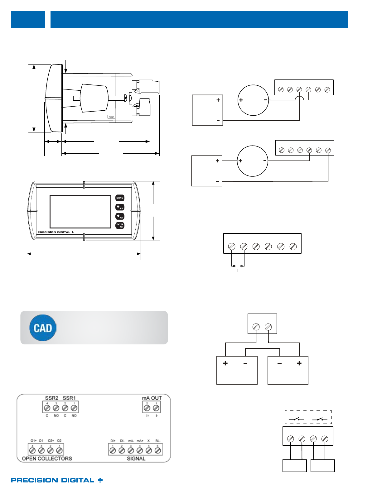
▲ Connector Labeling for Fully Loaded Loop Leader
The connectors’ label, axed to the meter, shows the location of all
connectors available with requested conguration.
Notes:
1. Panel cutout required: 1.772" x 3.622" (45 mm x 92 mm)
2. Panel thickness: 0.040 - 0.250" (1.0 mm - 6.4 mm)
3. Mounting brackets lock in place for easy mounting
4. Clearance: Allow 6" (152 mm) behind the panel
1.76"
(45mm)
0.59"
(15mm)
3.2"
(81mm)
2.45"
(62mm)
3.6"
(91mm)
4.68"
(119mm)
2.45"
(62mm)
▲Meter Dimensions - Side View
▲ Meter Dimensions - Front View
4-20 mA
Transmitter
Power
Supply
DI+ DI- mA- mA+ BL-X
4-20 mA
Transmitter
Power
Supply
DI+ DI- mA- mA+ BL-X
The following gures show a 4-20 mA loop connected to the meter.
The rst gure shows the connection without the backlight and
the second shows the connection with the backlight. The meter is
powered by the 4-20 mA current loop.
▲ 4-20 mA Input Connection without Backlight
▲ 4-20 mA Input Connection with Backlight
I+ I-
Power
Supply
Device with
4-20 mA Input
Connections for the 4-20 mA transmitter output are made to the
connector terminals labeled mA OUT. The 4-20 mA output must be
powered from an external power supply
A digital input is standard on the meter. This digital input is
connected with a normally open contact across DI+ and DI-, or
with an active low signal applied to DI+.
DI+ DI- mA- mA+ BL-X
C NO C NO
Internal
Load Load
Relay connections are made to a
four-terminal connectors. Each relay’s
C terminal is common only to the
normally open (NO) contact of the
corresponding relay.

www.predig.com
9
Open collector output 1 and 2
connections are made to
terminals labeled O1+ and O1-,
and O2+ and O2-. Connect the
alarm or pulse input device as
shown below.
On or O; user programmable, 8 characters
maximum. Displayed every 10 seconds for 1 second on bottom line.
Ambient > -10°C: 1 update/second
Ambient = -20°C: 1 update/2 seconds
From -20°C to -40°C the update rate slows down 1 second for every
-2°C (e.g. at -24°C, 1 update/4 seconds).
Top: 99999; Bottom: 99,999,999 (ashing)
Top: -9999; Bottom: -9,999,999 (ashing)
II 1G, Ex ia IIC T4 Ga, Ta = -40°C to +70°C
Certificate number: CML 17ATEX2015X
Ex ia IIC T4 Ga, Tamb = -40°C to +70°C
Certificate number: IECEx CML 17.0008X
Class I, Division 1, Groups A, B, C and D T4
Class I, Division 2, Groups A, B, C and D T4
Ex ia IIC T4 (Canada); Class I Zone 0, Zone 1,
AEx ia IIC T4 (U.S.)
Class I Zone 2, Group IIC T4 (U.S.)
PROCESS CONTROL EQUIPMENT FOR USE IN HAZARDOUS
LOCATIONS
IEC 61010-1:2010 (3rd Edition);
UL 61010-1, 3rd Edition;
CAN/CSA-C22.2 No. 61010-1-12, 3rd Edition;
UL 50E
Operating temperature range:
-40 to 75°C for safe area products
-40 to 70°C for hazardous area products
Storage temperature range: -40 to 85°C
Relative humidity: 0 to 90% non-condensing. Printed circuit boards
are conformally coated.
Front panel & Free PC-based USB
programming software
Enclosure: 1/8 DIN, IP65, NEMA 4X front
panel, high impact plastic, NORYL®polyphenylene ether & polystyrene
blend (PPE PS) resin, UL 94V-0, Color: gray, Gasket: silicone rubber,
Faceplate: LEXAN®polycarbonate (PC) film, Buttons: silicone rubber
Averages the input signal over a period of time between
1 and 16 seconds to dampen the effects of a noisy signal that causes
a jumpy display.
0.0 to 99.9% of full scale. Input signal changes
greater than bypass value are displayed immediately.
Recalibration is recommended at least every 12
months.
Max/min readings reached by the process are
stored until reset by the user or until power to the meter is turned off.
There are three password types available: Main, Total,
and Grand Total. The Main password prevents access to the meter
Programming Mode. Total and Grand Total passwords prevent
resetting the total and grand total, respectively.
All programmed settings and total and grand
total values are stored in non-volatile memory for a minimum of ten
years if power is lost.
64 dB at 50/60 Hz
Removable screw terminals accept 12 to 22 AWG.
2.1 VDC on contact. Connect normally
open contacts across DI+ and DI-
Logic High: 2.4 to 30 VDC (max)
Logic Low: 0 to 0.9 VDC
Screw terminal connectors: 4.5 lb-in (0.5 Nm)
Mounting screws: 8.0 lb-in max. (0.9 Nm)
4.68" x 2.45" x 3.79"
(119 mm x 62 mm x 96 mm) (W x H x D)
8.7 oz (247g) with option board
3 years parts and labor
Except where noted all specifications apply to operation at +25°C.
4-20 mA
±0.02% of span ±1 count, Square root and programmable
exponent: 10-100% FS
Without backlight: 1.5 V maximum,
With backlight: 4.5 V maximum
With backlight o: 75 Ω @ 20 mA
With backlight on: 225 Ω @ 20 mA
Over current protection to 1 A maximum
Over voltage protection to 30 VDC max
(between mA+ and mA-/BL-)
25 PPM/°C from -40 to 75°C ambient
Linear, square root, or programmable exponent
0.0 to 999,999.9
Analog input will not interfere with existing
HART communications on the wired 4-20 mA signal.
Dual-line LCD with backlight. Both lines 14-segment
alphanumeric. Top: 0.7" (17.8 mm), Bottom: 0.4" (10.2 mm). Display
may be programmed to turn red and ash a user-dened message on
alarm condition.
Powered by 4-20 mA loop. Intensity varies with signal level
Top line: 5 digits (-9999 to 99999) or 5 characters (all capital & most
lower case letters)
Bottom line: 8 digits (-9,999,999 to 99,999,999; separated by commas)
or 8 characters (all capital & most lower case letters)
Top line: 5 digits (-9999 to 99999) or 5 characters (all capital & most
lower case letters)
Bottom line: 8 digits (-9,999,999 to 99,999,999; separated by commas)
or 8 characters (all capital & most lower case letters)
Bargraph: 20 segments, numeric percent indication at top
Top line: Up to four decimal places
Bottom line: Up to seven decimal places and commas to indicate
1000s (e.g. 88,987,628)
The input can be displayed in dierent scales on
the top and bottom lines. For instance, the top line could display the
ow in GPM and the bottom line could display that same input in CFM.
Red backlight, ashing display, alarm symbol (!)
Symbols are not available on bargraph models. Bargraph segment
flashes on alarm.
O1+ O1- O2+ O2-
5-30 VDC
90 mA MAX
Power Supply
External DC
Relay
+-
+
Alarm Indicator/
Pulse Counter
(e.g. PD6300)
-
Internal
See Control Drawing LIM6600-2
for information on hazardous area wiring
at www.predig.com/PD6626
!
O1+ O1- O2+ O2-
5-30 VDC
90 mA MAX
Power Supply
External DC
Relay
+-
+
Alarm Indicator/
Pulse Counter
(e.g. PD6300)
-
Internal

www.predig.com
10
Top display: -9999 to 99999; bottom
display: -9,999,999 to 99,999,999 (with commas)
Top display: -9999 to
99999; bottom display: -9,999,999 to 99,999,999 (with commas)
Up to 9,999,999,999,999
using both lines with 13-digit total feature enabled.
On bottom display; “T” indicates
total and “GT” indicates grand total (not available on bargraph models)
Up to four decimal places on top, up to seven
decimal places on bottom. Total decimal point is independent of rate
decimal point.
Calculates total based on rate and rate units to display
total in engineering units. A custom factor must be programmed if
using custom defined units.
Seconds, Minutes, Hours, Days
Totalizer rolls over when display exceeds
99,999,999 (9,999,999,999,999 if 13-digit limit enabled). Relay status
reflects display.
Via front panel button or external
contact closure on digital input
Total and grand total
passwords may be entered to prevent resetting the total or grand total
unless a password is entered.
Grand total reset may be disabled
through the meter interface. Grand total reset may be permanently
disabled by selecting YES at the PERMLOCK menu.
Caution: Once the Grand Total has been programmed as
“non-resettable” the feature cannot be disabled
User programmable for high or low alarm
0-100% FS, user programmable
0 to 9,999 seconds
Independent for each open collector and relay
Fail-safe: on, the output is on under normal conditions
Fail-safe: off, the output is on under alarm conditions
Automatic, Automatic with manual override,
Latching (manual reset anytime), Latching with reset after cleared
(manual reset only after alarm has cleared)
Red backlight, flashing display, alarm symbol
(!) (symbols not available on bargraph models) Bargraph segment
flashes on alarm.
On or Off; User programmable, 8 characters
maximum. Displayed every 10 seconds for 1 second on bottom line
Front panel ACK button or external digital
input resets output and screen indication
When power is applied to the meter, open
collectors and relays will reflect the state of the input to the meter.
One-shot or Continuous
Off Time Delay: 1 sec to 99:59:59 (hrs:min:sec)
On Time: 1 sec to 99:59:59 (hrs:min:sec)
Output turns on when started and off when stopped
Two NPN, Isolated open collector, 5-30 VDC @ 150mA max
Pulse, Alarm, Timer, Total Reset, Stopwatch
on/off, or Disable
Rate, Total, Grand Total, or Test Frequency
0.000001 to 999,999.9
0.5 ms @ 1 kHz; 500 ms @ 1 Hz; 50% duty cycle
1,000 Hz maximum
Available for Output 2 (90° behind
Output 1)
Assign to Rate, Total, Grand Total or Digital
Input
250 VAC/VDC @ 1A resistive
75VA; 250VAC; 0.6A pilot duty (inductive) – UL Code D300
25VA; 250VDC; 0.6A pilot duty (inductive) – UL Code R300
Metal oxide varistors across outputs
Alarm, Sample, Timer, Batch, Stopwatch on/off,
or Disable
Assign to Rate, Total, Grand Total, or Digital
Input
Meter will keep track of how long each relay has
operated and display this information
Meter will keep track of how many times the relays
have cycled and display this information
±0.05% FS ±0.001mA
Rate, total, re-transmit; reverse scaling allowed
1.00 to 23.0 mA
High impedance state, less than 1 mA
Factory calibrated 4.00 to 20.00 mA
1.0 mA, 3.5 mA, or 3.8 mA (If input < 3.5 mA), or Off;
user selectable
20.5 mA, 20.8 mA, or 23.0 mA (If input > 20.5 mA), or Off;
user selectable
500 V input-to-output
0.5 μA/°C max from -40 to 75°C ambient
7.0 VDC to 30.0 VDC maximum
10-750 Ω @ 24 VDC;
100-1100 Ω @ 30 VDC
Automatic or Manual, count up or count down
Pressing F1 function key starts the batch
Pressing F3 once pauses the batch,
pressing it twice cancels the batch
The Loop Leader can be used as an automatic
batch controller where batches run continuously without operator input.
Single or dual-relay batching with optional
preclose for dual-stage operation
Set via F2 function key anywhere between 0.0001 to
99,999 based on batch total decimal point. If batch total is assigned to
bottom, the preset can be up to 8 digits.
For two-stage batch application, a preclose value
can be set to close the main flow line.
1 to 9,999 seconds. The batch will
automatically restart after completion of the last batch.
Microsoft®Windows®7 & 10
USB 2.0 (Standard USB A to Micro USB B)
Configure meters one at a time
Generate with or without meter connected. Save
to file for later use.
Meter is powered by USB connection during
programming.
Try our convenient
meter selection utility
for all models at
www.predig.com/msu
www.predig.com
11
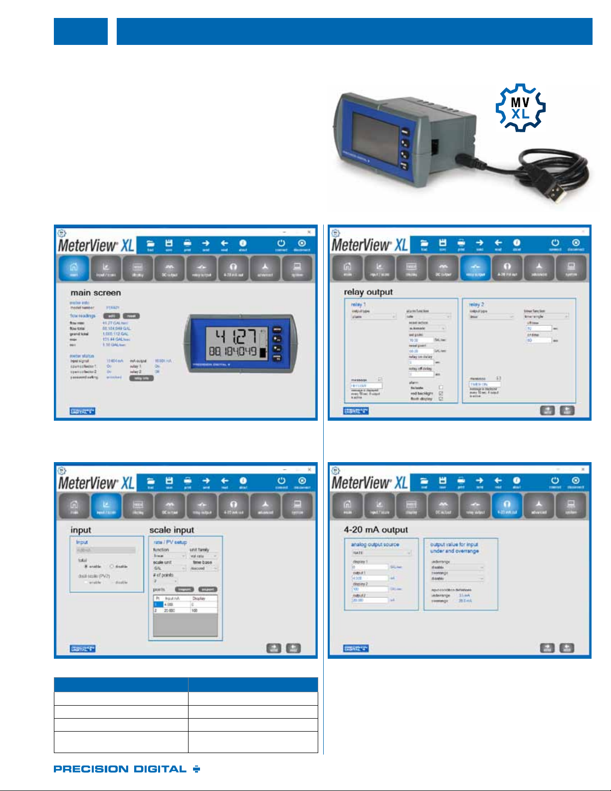
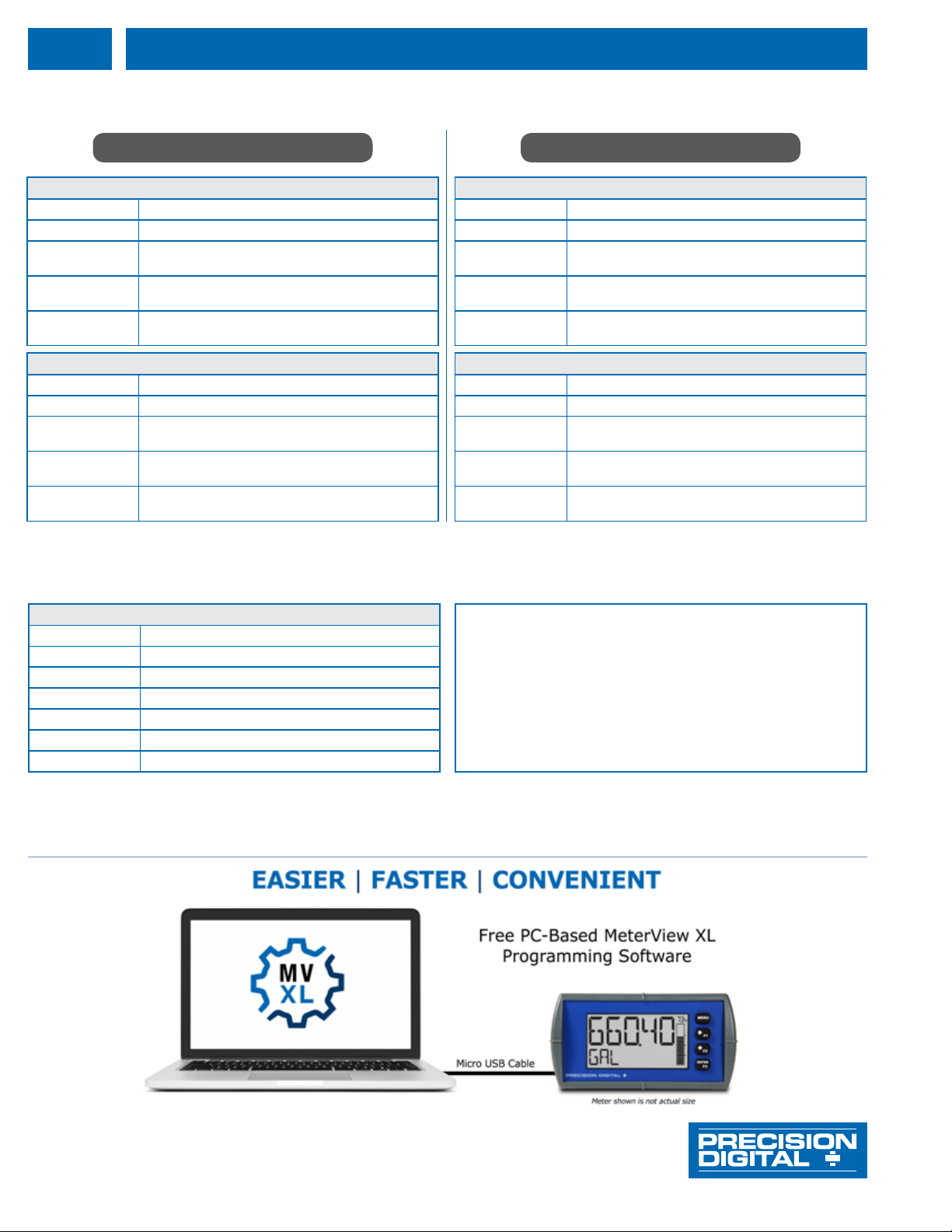
Free, PC-based, MeterView XL software that connects to the meter
via a micro USB cable is available for programming and setup of the
meters. This software greatly simplifies the programming process
and also allows the user to save configuration files for later use. The
meter will also be powered by the USB connection so no additional
power is needed during programming.
▲ The main screen displays an image of the connected meter and
includes various information about this meter, such as model
number, readings, and status.
▲ The Input/Scale window is used to: ▲ The 4-20 mA Output window is used to program the isolated
4-20 mA output’s source, range, and under and over range values.
Function tHiS MEtER
Set the input 4-20 mA
Enable/disable the totalizer Totalizer enabled
Enable/disable the dual-scale feature Dual scale disabled
Scale the input Linear input, unit is gallons,
2 cal points, 4-20 mA = 0-100 GAL
●Free PC-Based USB Programming Software
●Easy Programming of Features Packed Product
●USB Connection Provides Power During Programming
●Save & Print Configuration Files without Meter Connected
●Micro USB Cable Provided
▲ The Relay Output window is used to assign a specific task to the
2 relays such as alarm, sample, timer, stopwatch, or off. A custom
message that will flash every 10 seconds can also be added.
PD6626–LNN* Loop-Powered, Hazardous Area, No Options
PD6626–L2N Loop-Powered, Hazardous Area,
Two Solid State Relays
PD6626–L3N Loop-Powered, Hazardous Area,
4-20 mA Analog Output
PD6626–L5N* Loop-Powered, Hazardous Area,
Two Solid State Relays and 4-20 mA Analog Output
PD6628–LNN* Loop-Powered, Hazardous Area, Bargraph, No Options
PD6628–L2N Loop-Powered, Hazardous Area, Bargraph,
Two Solid State Relays
PD6628–L3N Loop-Powered, Hazardous Area, Bargraph,
4-20 mA Analog Output
PD6628–L5N* Loop-Powered, Hazardous Area, Bargraph,
Two Solid State Relays and 4-20 mA Analog Output
The information contained in this document is subject to change without notice. Precision Digital
Corporation makes no representations or warranties with respect to the contents hereof, and
specically disclaims any implied warranties of merchantability or tness for a particular purpose.
©2018 Precision Digital Corporation. All rights reserved.
PDA2301 NEMA 4X Plastic Enclosure
PDA2501 Plastic NEMA 4X Enclosure
PDA2601 Stainless Steel NEMA 4X Enclosure
PDA2701 Painted Steel NEMA 4 Enclosure
PDA2801 Low-Cost Plastic NEMA 4X Enclosure
PDA3407 Internally Mount NEMA 4X Plastic Enclosure
LDS6622_G 08/18
Precision Digital corPoration
PD6622–LNN* Loop-Powered, General Purpose, No Options
PD6622–L2N Loop-Powered, General Purpose,
Two Solid State Relays
PD6622–L3N Loop-Powered, General Purpose,
4-20 mA Analog Output
PD6622–L5N* Loop-Powered, General Purpose,
Two Solid State Relays and 4-20 mA Analog Output
PD6624–LNN* Loop-Powered, General Purpose, Bargraph, No Options
PD6624–L2N Loop-Powered, General Purpose, Bargraph,
Two Solid State Relays
PD6624–L3N Loop-Powered, General Purpose, Bargraph,
4-20 mA Analog Output
PD6624–L5N* Loop-Powered, General Purpose, Bargraph,
Two Solid State Relays and 4-20 mA Analog Output
1. All models come with two open collector outputs standard.
2. *Quick Shipment Program product, typically ships within 2 working days.
3. General Purpose Instruments are CE marked only.
4. Hazardous Area Instruments are UL Listed for both hazardous areas and general electrical safety and ATEX and IECEx certified as intrinsically safe.
This manual suits for next models
20
Table of contents
Popular Industrial Monitor manuals by other brands


tecnoelettra
tecnoelettra AT206 user manual

Moso
Moso Pop Pillar Brochure Holder Assembly guide

Advantech
Advantech FPM-2120G Series user manual

Bosch
Bosch Rexroth ctrlX HMI DE0015 operating instructions

Matrix Orbital
Matrix Orbital MOP-TFT480272-43A-BLM-TPC Hardware manual

Rockwell
Rockwell A-B Quality 6185-F quick start


