Precision Rated Optics OLT-301 SERIES User manual

OLT-301
S
ERIES Optical Loss Tester
Operation Guide
V.1.23.17

2
888-545-1254 | www.PrecisionRatedOptics.com
OLT-301 Series
Table of Contents
Safety Instructions....................................................................................................................................................4
1. General Information ............................................................................................................................................5
1.1 Scope of this Manual........................................................................................................................................5
1.2 Unpacking and Inspection................................................................................................................................5
1.3 Introduction......................................................................................................................................................6
2. Basic Operation ....................................................................................................................................................7
2.1 Foreword ..........................................................................................................................................................7
2.2 Instrument Details ............................................................................................................................................7
2.2.1 External Interfaces.....................................................................................................................................7
2.2.2 Keypad Operation......................................................................................................................................7
2.2.3 Indicator.....................................................................................................................................................8
2.3 Use of Battery...................................................................................................................................................8
2.4 Connector Cleaning..........................................................................................................................................8
3. Operation ..............................................................................................................................................................9
3.1 Power On..........................................................................................................................................................9
3.2 Stabilized Laser Source (SLS)........................................................................................................................11
3.2.1 SLS-Laser On/Off ...................................................................................................................................12
3.2.2 SLS-Reference Setting ............................................................................................................................12
3.2.3 SLS-Setup................................................................................................................................................13
3.3 Optical Power Meter (OPM)..........................................................................................................................13
3.3.1 OPM-Reference Setting...........................................................................................................................14
3.3.2 OPM-Save Record...................................................................................................................................14
3.3.3 OPM-Recall.............................................................................................................................................15
3.3.3 OPM-Trace..............................................................................................................................................15
3.3.4 OPM-Setup..............................................................................................................................................16
3.4 Optical Loss Test (OLT) ................................................................................................................................17
3.4.1 OLT-Reference Setting............................................................................................................................17
3.4.2 OLT-Bi-Directional Test.........................................................................................................................18
3.4.3 OLT-Save Record....................................................................................................................................19
3.4.4 OLT-Recall..............................................................................................................................................19
3.4.5 OLT-Threshold Setting ...........................................................................................................................20

www.PrecisionRatedOptics.com | 888-545-1254
3
OLT-301 Series
3.4.6 OLT-Setup...............................................................................................................................................20
3.5 Optical Return Loss Test (ORL)-Option........................................................................................................22
3.5.1 ORL-ORL Test........................................................................................................................................22
3.5.2 ORL-Save Record ...................................................................................................................................23
3.5.3 ORL-Recall..............................................................................................................................................24
3.5.3 ORT-Setup...............................................................................................................................................24
4. Maintenance and Calibration............................................................................................................................25
4.1 Cleaning of the Connectors............................................................................................................................25
4.2 Calibration Requirement ................................................................................................................................25
5. Warranty Information.......................................................................................................................................25
5.1 Terms of Warranty .........................................................................................................................................25
5.2 Exclusions ......................................................................................................................................................25
5.3 Warranty Registration ....................................................................................................................................26
5.4 Returning Instruments....................................................................................................................................26
5.5 Contact Customer Service..............................................................................................................................26

4
888-545-1254 | www.PrecisionRatedOptics.com
OLT-301 Series
Safety Instructions
Safety Terms Used in This Manual
WARNING
The WARNING sign denotes a hazard. It calls attention to a procedure which could result in personnel injury.
CAUTION
The CAUTION sign denotes a hazard. It calls attention to an operating procedure if not correctly performed or
adhered to, could result in damage to or destruction of part or the entire product.
NOTE
The NOTE sign information that may be beneficial during the use and maintenance of the instrument.
WARNING
OLT-301 Series Optical Loss Tester is a laser device. User should always avoid direct eye exposure to the laser
output. Using microscope or magnifier to observe the laser output should also be avoided: laser beam may
converge on the retina and cause permanent eye injury.
CAUTION
Battery: OLT-301 Series battery type is lithium battery.
Battery Power Supply: Do not expose battery to fire or intense heat. Do not open or mutilate battery. Avoid
touching the electrolyte in the battery, which is corrosive and may cause injuries to eyes, skin or damage to
clothes.
External Power Supply: OLT-301 Series support external power supply: 5V DC/750mA. External power supply
is optional.
Laser Radiation: To avoid serious eye injury, never look directly into the optical outputs of fiber optic network
equipment, test equipment.
•Always avoid looking directly into the optical output port, when the instrument is working.
•Always replace protective dust cap on the detector port when the instrument is not in use.
•Always avoid looking directly at unconnected end of optic fiber in testing and make the unconnected end
pointing at a non-reflective object.

www.PrecisionRatedOptics.com | 888-545-1254
5
OLT-301 Series
1. General Information
1.1 Scope of this Manual
Thank you for purchasing a Precision Rated Optics instrument. Please read this manual carefully before using
Precision Rated Optics fiber optic instrument. Always be aware of the Warning and Caution signs appearing
throughout this manual.
This manual contains the information necessary for proper operation and maintenance of a Precision Rated
Optics instrument, troubleshooting instructions as well as information regarding maintenance services.
All Precision Rated Optics instruments are carefully assembled and undergo rigorous mechanical, electrical, and
optical inspection prior to shipment. Beside the instrument, the package also includes a lithium battery pack, a
charging/data transfer cable, a power adapter, a FC/UPC adapter and this user's manual. For detailed information,
please refer to the packing list.
Upon receiving the instrument, please check for any obvious signs of physical damage that may have occurred
during shipment. Report any damage to the shipping agent or the representative of PRO immediately. Retain the
original packing materials in case reshipment is necessary.
1.2 Unpacking and Inspection
This instrument has been carefully packed in accordance with standard shipping procedures. Examine the
instrument for damage that may have occurred during shipment. If you find any damage or the instrument is not
working, or if any of the following items are not included, please contact your representative of PRO.
If necessary, you may contact PRO via this email: sales@PrecisionRatedOptics.com.
NOTE
To return the instrument in the case of repair, calibration or other maintenance, please note the following:
•Be sure to pack the instrument with soft cushion like Polyethylene, so as to protect the shell of the
instrument.
•Please use the original hard packing box. If use other packing material, please ensure at least 3 cm soft
material around the instrument.
•Be sure to correctly fill out and return the warranty registration card, which should include the following
information: company name, postal address, contact, phone number, e-mail address and problem
description.
•Be sure to seal the packing box with exclusive tape.
•Be sure to ship to your representative or the agent of the Company in a reliable way.

6
888-545-1254 | www.PrecisionRatedOptics.com
OLT-301 Series
1.3 Introduction
The Precision Rated Optics OLT-301 Series Intelligent Optical Loss Tester combines stabilized laser source and
optical power meter which can perform automatic bi-directional loss test (when used in pairs) on single fiber with
Pass/Fail assessment to offer user-friendly operation and avoid potential operational mistakes. The rugged and
easy-to-use OLT-301 Series is the ideal optical loss tester for FTTx, LAN and CATV application.
Features:
•All-in-one: SLS + OPM + OLT + ORL + Length test
•Optical power monitoring (Auto power trace)
•Bi-directional loss test on single fiber
•ORL test
•Pass/Fail assessment
•Automatic wavelength identification/switch (AutoID)
•Remote reference value setting
•Internal clock & fiber S/N editable
•1000 test records (CSV) storage & management
•Data transfer to PC via USB (Driver-free)
•Auto test records save in local unit/remote unit/both units
•USB power charging
•Over 35 hours continuous operation
•Multilanguage support
•No warm-up, quick start
•High resolution color LCD
•Pocketsize, lightweight and easy-to-use
Automatic Wavelength Identification
Compatible with the digital encryption protocols of its laser source module and PRO Series Stabilized Laser
Source, the OLT-301 Series tester can automatically identify the wavelength of the input optical signal and switch
to the corresponding test mode, which greatly reduces the workload at both ends and avoids potential error.
Automatic Bidirectional Loss Test on Single Fiber
One OLT-301 Series tester at each end of a single optical fiber can perform bi-directional loss test by just pressing
one unit and can automatically measure and display the entire fiber attenuation to help users acquire complete and
accurate optical fiber loss information.
Applicable to FTTx/PON testing
The OLT-301 Series tester can be used to measure Triple-play signals (1310nm, 1490nm and 1550nm) on Passive
Optical Network (PON)
www.PrecisionRatedOptics.com | 888-545-1254
7
OLT-301 Series
2. Basic Operation
2.1 Foreword
This part introduces the basic operation on the OLT-301 Series testers. Specific operations are elaborated in
Chapter 3 of this manual. Please read this manual carefully for optimal operation. If you encounter any problems
during operation, you are welcome to contact the technical staff of our company or representatives.
2.2 Instrument Details
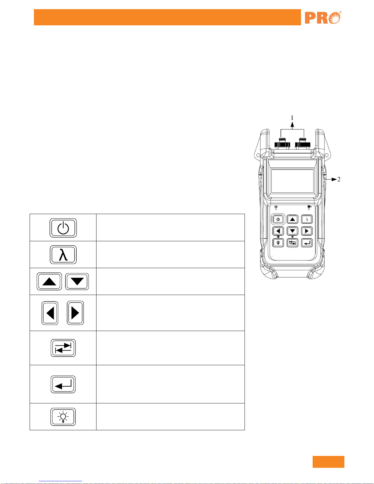
2.2.1 External Interfaces
1. Optical Input & Output
The OLT-301 Series is available with FC connector (Interchangeable SC/ST).
Note: Output port is marked with “LS”; Input port is marked with “PM”.
2. USB Power /Data Port
The OLT-301 Series can be charged by external power adapter (5V DC, 750mA).
2.2.2 Keypad Operation
Power on/off
Toggle between wavelengths
Toggle between setup items;
Adjust value in setup mode
Toggle between sub-interfaces in working mode;
Shift digit positions in setup mode
Toggle between working modes: SLS, OPM, OLT
& ORL;
Long press to enable/disable Auto Power Off
Enter setup mode;
Execute or toggle between setup values;
Confirm
Short press to turn backlight on/off;
Long press to set contrast

8
888-545-1254 | www.PrecisionRatedOptics.com
OLT-301 Series
2.2.3 Indicator
Charging Indicator
Laser Indicator (Illuminate when laser emits)
2.3 Use of Battery
The OLT-301 Series works on lithium battery. Please make sure battery is mounted properly before use. When
battery is low, low battery indicator will appear on LCD. You can still use the OLT-301 Series as long as its
display on LCD is identifiable. When LCD display becomes dim, laser source output will become unstable and
power meter measurement will be inaccurate. Please charge as soon as possible when battery is low to ensure
accurate measurement.
NOTE
Please take out the battery of the OLT-301 Series if it is not in use for a long time.
2.4 Connector Cleaning
Please follow the instructions below when cleaning:
•Turn off the instrument before cleaning.
•Non-compliant operation may result in hazardous radiation exposure.
•Turn off laser source before cleaning optical interface.
•Always avoid looking directly into the optical output port when the instrument is working, laser is
invisible and can cause serious eye damage.
•Disconnect instrument from power supply before cleaning to prevent electric shock.
•Do not install unauthorized parts or make unauthorized adjustments on instrument.
•Please consult qualified professional about maintenance and repair services.
NOTE
Always clean the optical connectors before using the OLT-301 Series to ensure accurate measurement. Clean the
optical connector gently with cleaning swab.
NOTE
Inappropriate maintenance may result in low performance or error:
•Distance error increases;
•Linearity error;
•Extra optical power attenuation;
•Received optical power is beyond normal range.

www.PrecisionRatedOptics.com | 888-545-1254
9
OLT-301 Series
3. Operation
3.1 Power On
Press and loading screen appears
Then it enters functional interface (The last interface before last shutdown), see Figure 3.2.
Figure 3.2
The toggle between functional interfaces:
Press to toggle [Main menu] interface, see Figure 3.3.
Figure 3.3

10
888-545-1254 | www.PrecisionRatedOptics.com
OLT-301 Series
1. Press and to toggle the following function interface:
2. Press and to toggle the corresponding function interface;
3. Press to enter the corresponding function interface.
The toggle between different setting interfaces:
Under [ ] function interface, press and to toggle the following
interfaces:
Under [ ] function interface, press and to toggle the following interfaces:
Under [ ] function interface, press and to toggle the following interfaces:
Under [ ] function interface, press and to toggle the following
interfaces:
www.PrecisionRatedOptics.com | 888-545-1254
11
OLT-301 Series
The system setup
Press to enter [ ] function interface: Press , and to enter and edit the
Date, Time, Brightness, Auto Off and Language.
USB configuration
Press to enter [ ] function interface: Press and to select:
Mass storage: PC recognition it for a USB flash drive;
Communication: the equipment directly transfer the data to the PC software, mainly used in the optical power
meter "Draw Trance" function, the power fluctuations will be shown in the PC software.
Device information
After press , it will display the version of software and hardware.
3.2 Stabilized Laser Source (SLS)
Press and to the following interface, see Figure 3.4.
Figure 3.4

12
888-545-1254 | www.PrecisionRatedOptics.com
OLT-301 Series
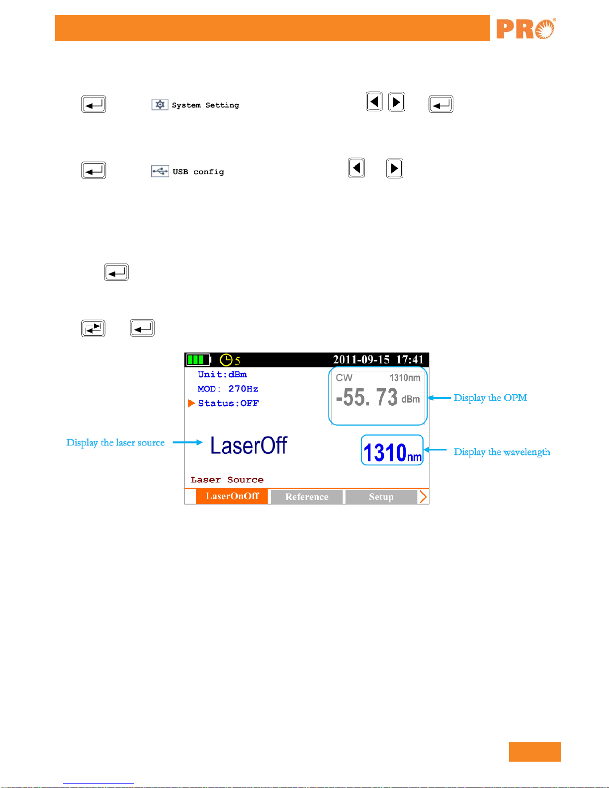
3.2.1 SLS-Laser On/Off
Press and to [LaserOnOff] sub-interface, see Figure 3.4;
Press to turn on laser source, see Figure 3.5; press again to turn off laser, see Figure 3.5;
Figure 3.5
Press to select “MOD” option, press the output mode toggles between CW, 270Hz, 1KHz, 2KHz
and AutoID;
Press to select “Unit” option, press the output power unit and value toggle between dBm and mW.
3.2.2 SLS-Reference Setting
Note: This function is only for AutoID mode applicable, "Ref: XXX. XXdBm" parameters will set up to the
opposite side which has the corresponding models test instrument; this is only for the test reference.
Press and to [Reference] sub-interface, see Figure 3.6;
Figure 3.6
Press and to select “Set reference” and “Get from OPM”. “Set reference “: press to enter and
edit power value, select “OK” and press to confirm. At this time on the right-bottom of the screen it will
display
“Ref.Power:-10.00dBm”, means -10dBm is the value you just set, and this value will send to the opposite side.
www.PrecisionRatedOptics.com | 888-545-1254
13
OLT-301 Series
“Get from OPM”: press to set the current power value which gets from OPM as the reference.
Press to toggle between the different wavelengths.
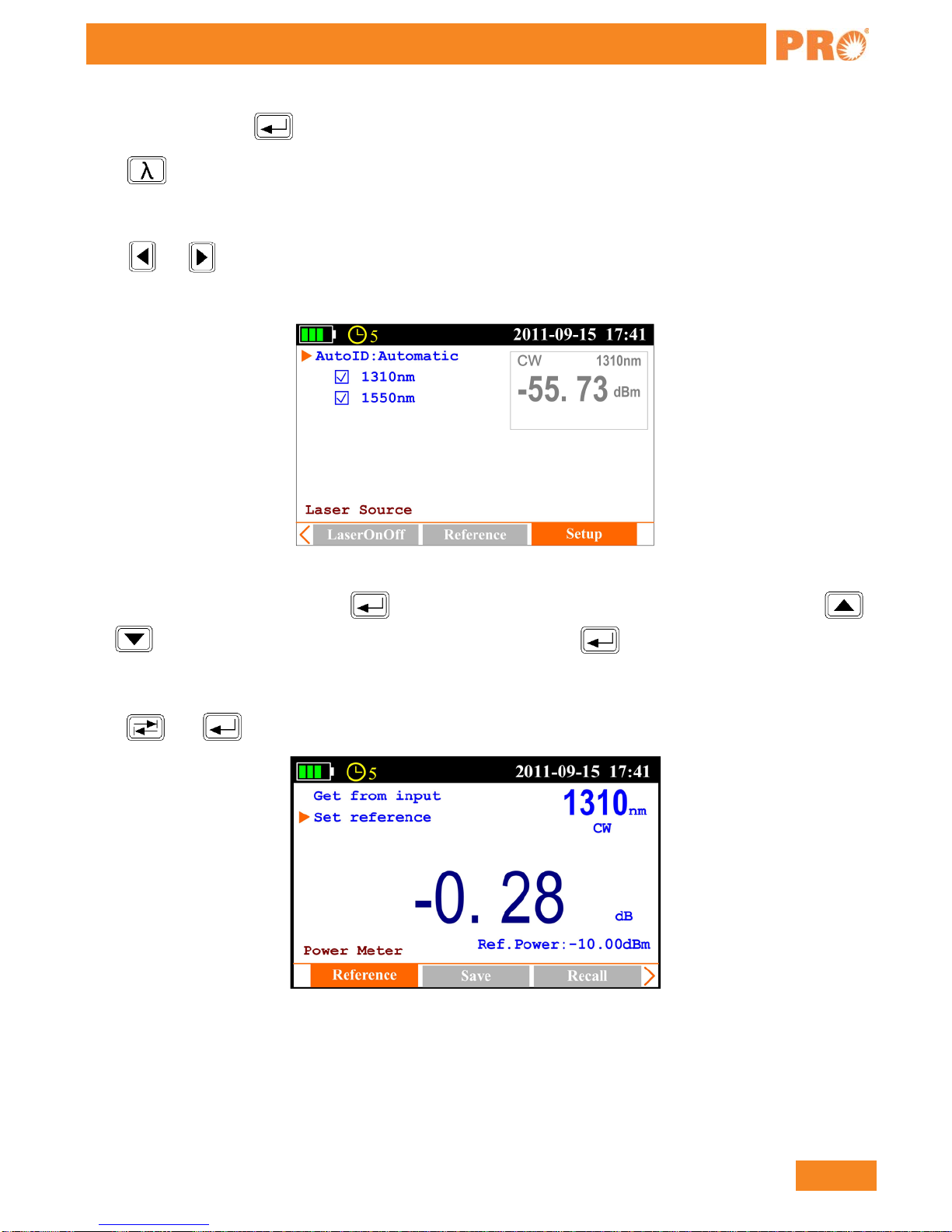
3.2.3 SLS-Setup
Press and to [Setup] interface, see Figure 3.7.
Note: This function is only for Auto ID mode applicable.
Figure 3.7
While the cursor on “Auto ID “, press to select Manual or Automatic. Under Automatic mode, press
and to move to the certain wavelength (1310nm, 1550nm), press to select it or not.
3.3 Optical Power Meter (OPM)
Press and to [Power Meter] interface, see Figure 3.8.
Figure 3.8
14
888-545-1254 | www.PrecisionRatedOptics.com
OLT-301 Series
3.3.1 OPM-Reference Setting
Press and to [Reference] sub-interface, see Figure 3.8.
Press and to select item: Set reference and Get from input power, press to enable adjustment, press
to adjust the value, and press to confirm.
NOTE
Set reference
Refers to manual reference value setup; if the laser source (Precision Rated Optics laser source with AutoID
function) on the other side of the tested fiber enables AutoID, the OPM will automatically set the reference value
sent from the laser source as reference (“AutoID” will appear in this interface).
Get from input power
Sets the current measured power value as reference value.
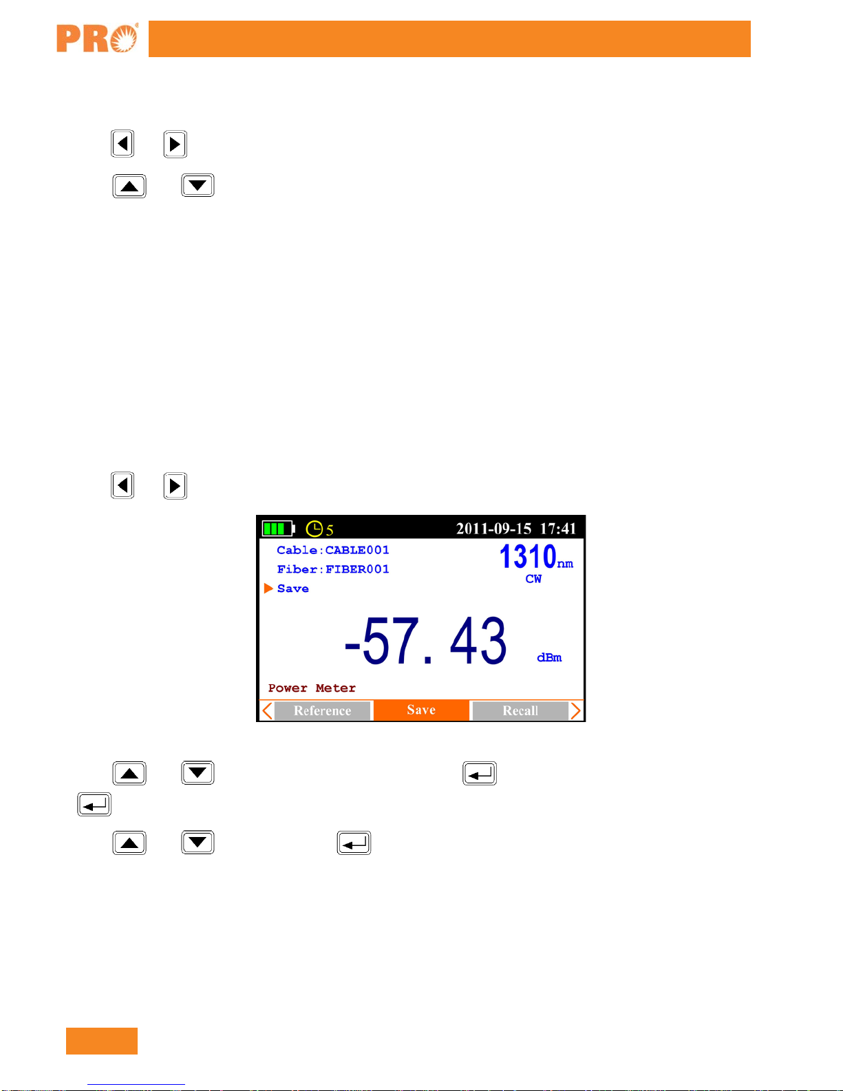
3.3.2 OPM-Save Record
Press and to [Save] sub-interface, see Figure 3.9.
Figure 3.9
Press and to select item: Cable: and Fiber: press to edit the information, and then press
to confirm.
Press and to select Save, and press to save current record.
www.PrecisionRatedOptics.com | 888-545-1254
15
OLT-301 Series
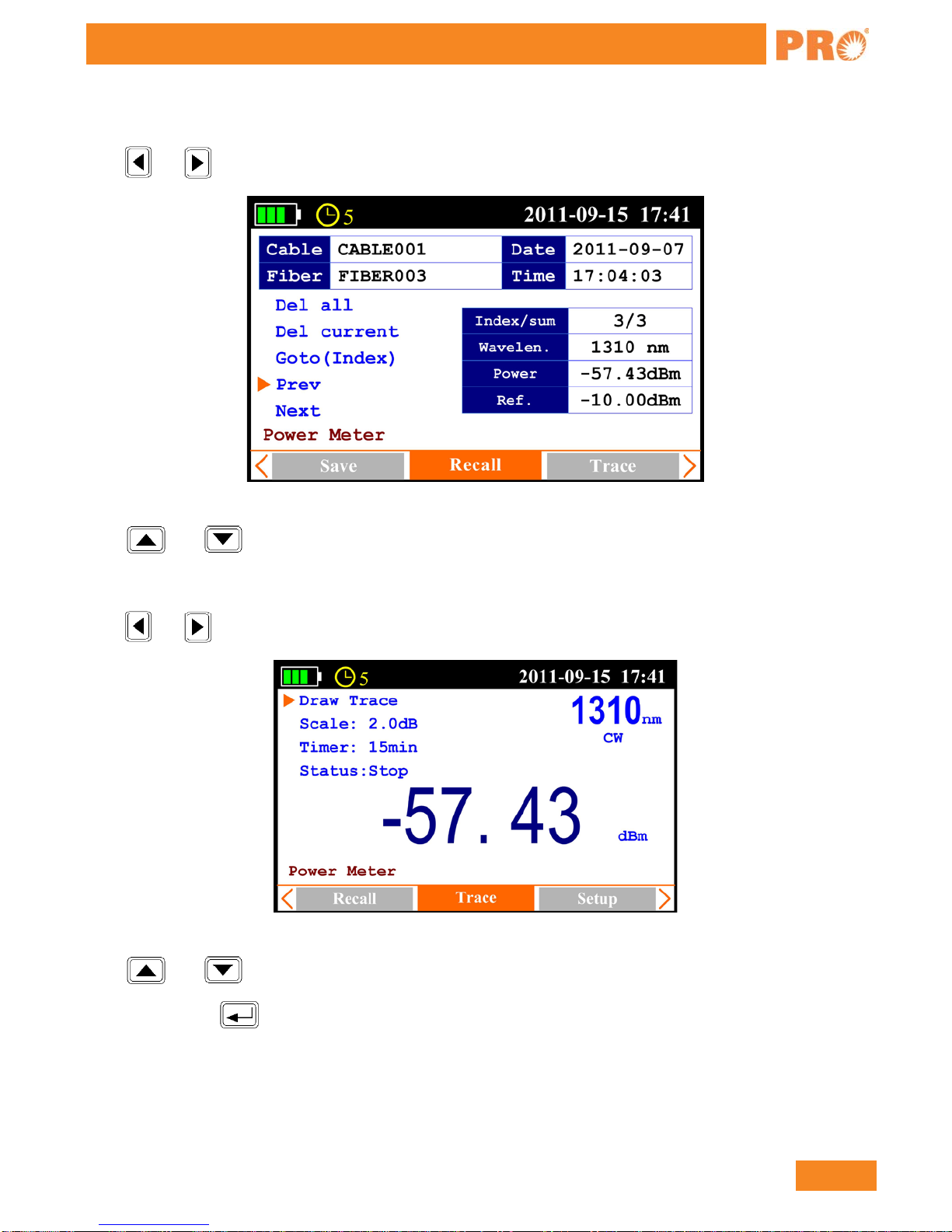
3.3.3 OPM-Recall
Press and to [Recall] sub-interface, see Figure 3.10.
Figure 3.10
Press and to select item: Del all, Del current, Go to (Index), Prev. and Next.
3.3.3 OPM-Trace
Press and to [Trace] sub-interface, see Figure 3.11.
Figure 3.11
Press and to select item: Draw Trace, Scale, Timer and Status.
Draw Trace: press , it will display the trace as Figure 3.12;

16
888-545-1254 | www.PrecisionRatedOptics.com
OLT-301 Series
Figure 3.12
Scale: press to select the suitable scale, press to confirm;
Timer: press and to select test time 15min, press to toggle between 15min, 60min and 8hour;
Status: press to running/stop trace.
3.3.4 OPM-Setup
Press and to [Setup] sub-interface, see Figure 3.13.
Figure 3.13
Press and to select item: Zero and Unit.
Zero: Screw on the dust cap, press the twice, the instrument will be automatically calibrate zero;
Note: this operation should do first in the use of optical power meter.
Unit: press and to select dBm, dB, mW.
Press to toggle between the different wavelengths.
www.PrecisionRatedOptics.com | 888-545-1254
17
OLT-301 Series
Operation Procedure:
1. Zero
2. Reference Setting
3. Input laser source
4. Read the power value
5. Save
6. Toggle the wavelength, and then repeat step 3, 4 and 5.
3.4 Optical Loss Test (OLT)
Press and to [Optical Loss Test] interface, see Figure 3.14.
Figure 3.14
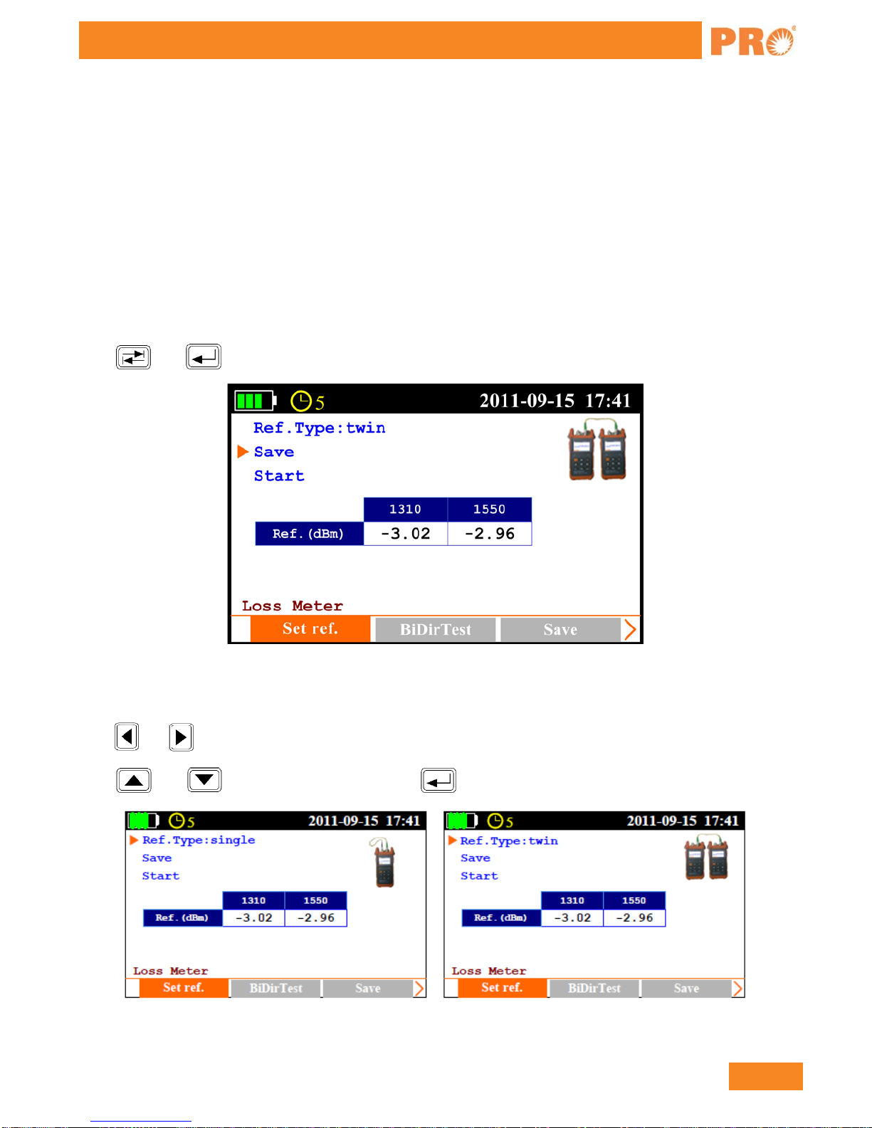
3.4.1 OLT-Reference Setting
Press and to [Set ref.] sub-interface, as shown in Figure 3.14.
Press and to select Ref. Type, and press to toggle between single and twin, see Figure 3.15.
Figure 3.15

18
888-545-1254 | www.PrecisionRatedOptics.com
OLT-301 Series
In single: the laser source port and power meter port connect to each other on the same unit, the power value
measured by the power meter is the reference value;
In twin: the optical loss test ports of two different units connect to each other by patch cord and the power value
measured in twin is more reasonable which is recommended.
After connecting the ports, press and to select Start, press to start the test.
Press and to select Save, press to save the measured value as reference value.
3.4.2 OLT-Bi-directional Test
Press and to [BiDirTest] sub-interface, as shown in Figure 3.16.
Figure 3.16
Press and to select Start, and press to start the test.
Press and to select Save, and press to save the result.
Please also refer to 3.4.3 to save the result.
NOTE
Please complete Threshold setting and Reference setting before bi-directional test or it will affect test result.
www.PrecisionRatedOptics.com | 888-545-1254
19
OLT-301 Series
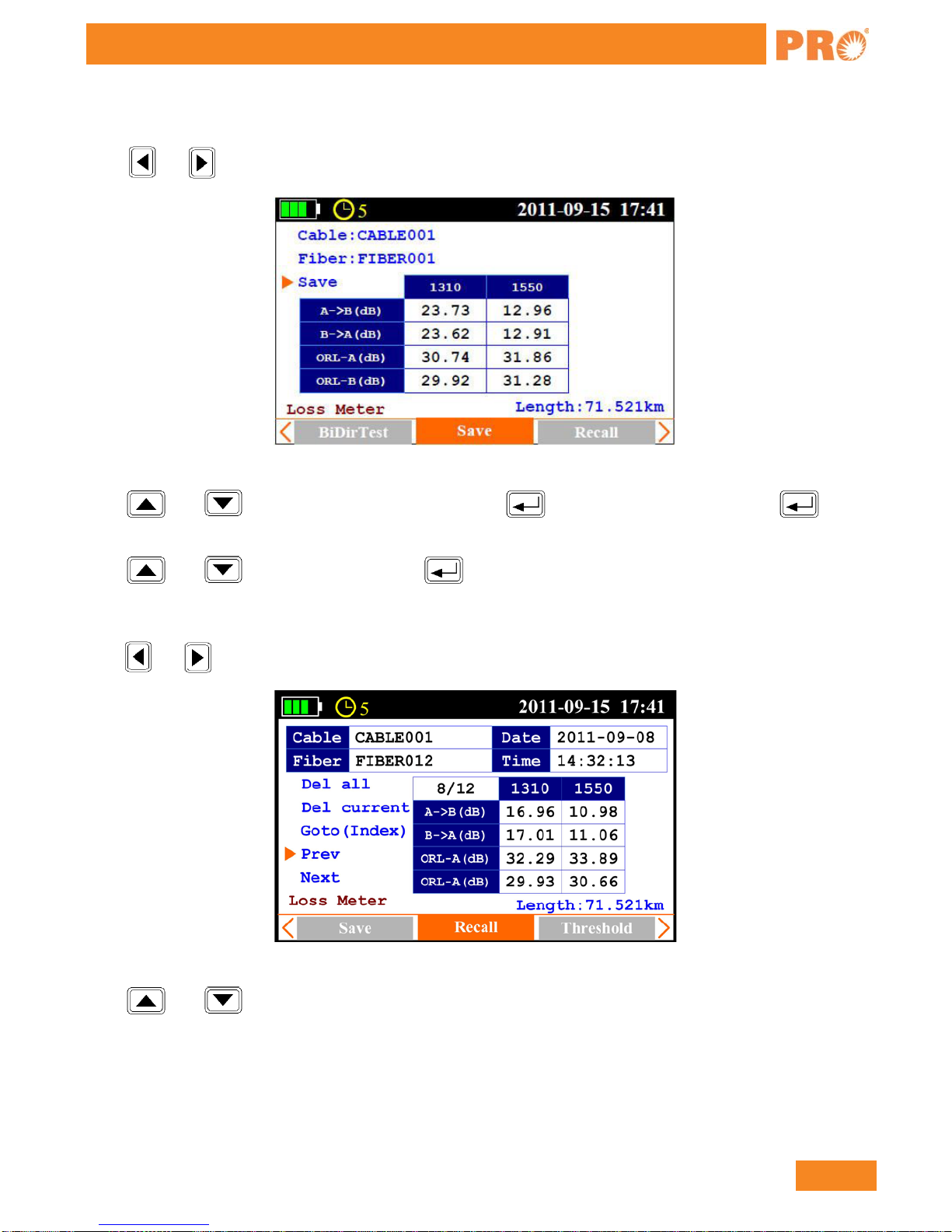
3.4.3 OLT-Save Record
Press and to [Save] sub-interface, as shown in Figure 3.17.
Figure 3.17
Press and to select item: Cable and Fiber, press to enable digit adjustment, press to
confirm.
Press and to select Save, and press to save current record.
3.4.4 OLT-Recall
Press and to [Recall] sub-interface, as shown in Figure 3.18.
Figure 3.18
Press and to select item: Del all, Del current, Go to (Index), Prev. and Next.
20
888-545-1254 | www.PrecisionRatedOptics.com
OLT-301 Series
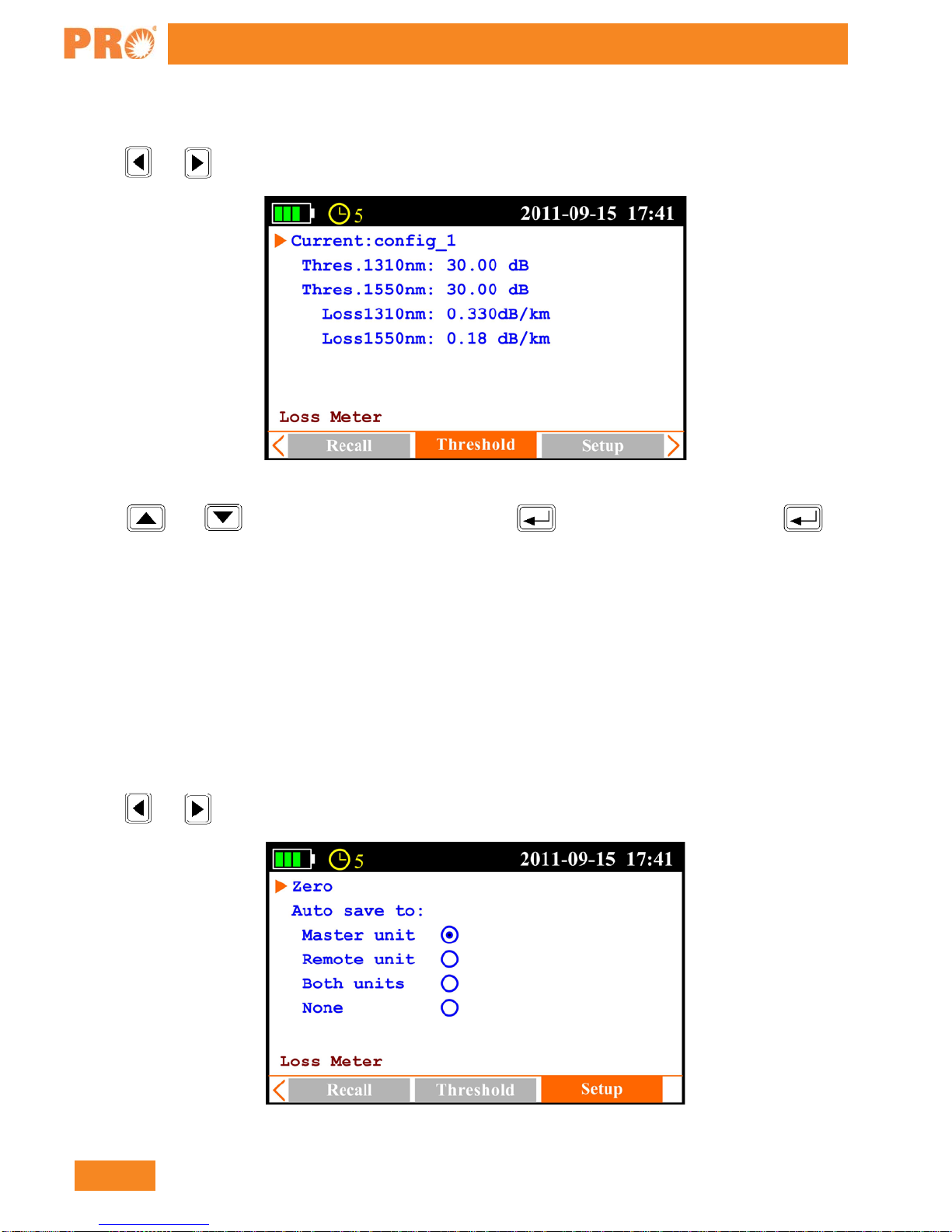
3.4.5 OLT-Threshold Setting
Press and to [Thresholds] sub-interface, as shown in Figure 3.18.
Figure 3.18
Press and to select the item to be adjusted, press to enable adjustment, and press to
confirm.
NOTE
Thres: In bi-directional test, the OLT-301 Series determines test result PASS or FAIL according to the
thresholds setting.
Loss: dB/km, In bi-directional test, the unit will calculate the fiber’s approximate length according to the
attenuation (dB/km) set here. Please note that the attenuation at each wavelength is setup separately, hence the
calculated length may be different at each wavelength. Non-fiber attenuation factors (connector, splices) and
incorrect attenuation setting may also affect the length calculation.
3.4.6 OLT-Setup
Press and to [Setup] sub-interface, as shown in Figure 3.19.
Figure 3.19
Table of contents
Other Precision Rated Optics Test Equipment manuals

Precision Rated Optics
Precision Rated Optics TP-P6 User manual

Precision Rated Optics
Precision Rated Optics VIP-35 User manual

Precision Rated Optics
Precision Rated Optics OLM-200 Series User manual

Precision Rated Optics
Precision Rated Optics VIP-55 User manual

Precision Rated Optics
Precision Rated Optics LS-200 SERIES User manual

Precision Rated Optics
Precision Rated Optics PRO-6350 User manual


