1. Lift the gasket upward and remove it from the center support
(Figure 9).
Figure 9
2. Extend a finger through the gasket opening and under the front
edge of the top cover. While pressing upward on the top cover,
use the heel of your hand to tap below its front edge and
release it (Figure 10). Repeat this step to release the other
side of the top cover.
3. While holding up the front edge of the top cover, use the heel
of your other hand to tap just below the back edge of the
cover. Lift the cover up and out of the way. Figure 10
4. Remove the two #10 x 3/4-inch screws from the bottom corners of the front cover
assembly.
5. Gently press in on each of the side covers, just behind the front edge and about 8 1/2
inches from the bottom, while pulling the front cover assembly forward to disengage it.
NOTE Each side cover has a small, triangular mark to indicate where to press.
6. Move the front cover assembly forward and slightly upward to remove it.
Rewire AMT for touchscreen console
WARNING DO NOT attempt to connect electrical power until all
assembly procedures are complete and the console is properly
installed.
Retrieve the following parts from the console package:
TV (coax) coupler
Ethernet (CAT 5) coupler and cable
Cable, and the console power cable
IMPORTANT Make sure all cables pass through all of the cable clips and DO
NOT allow any of the cables to hang near moving parts.
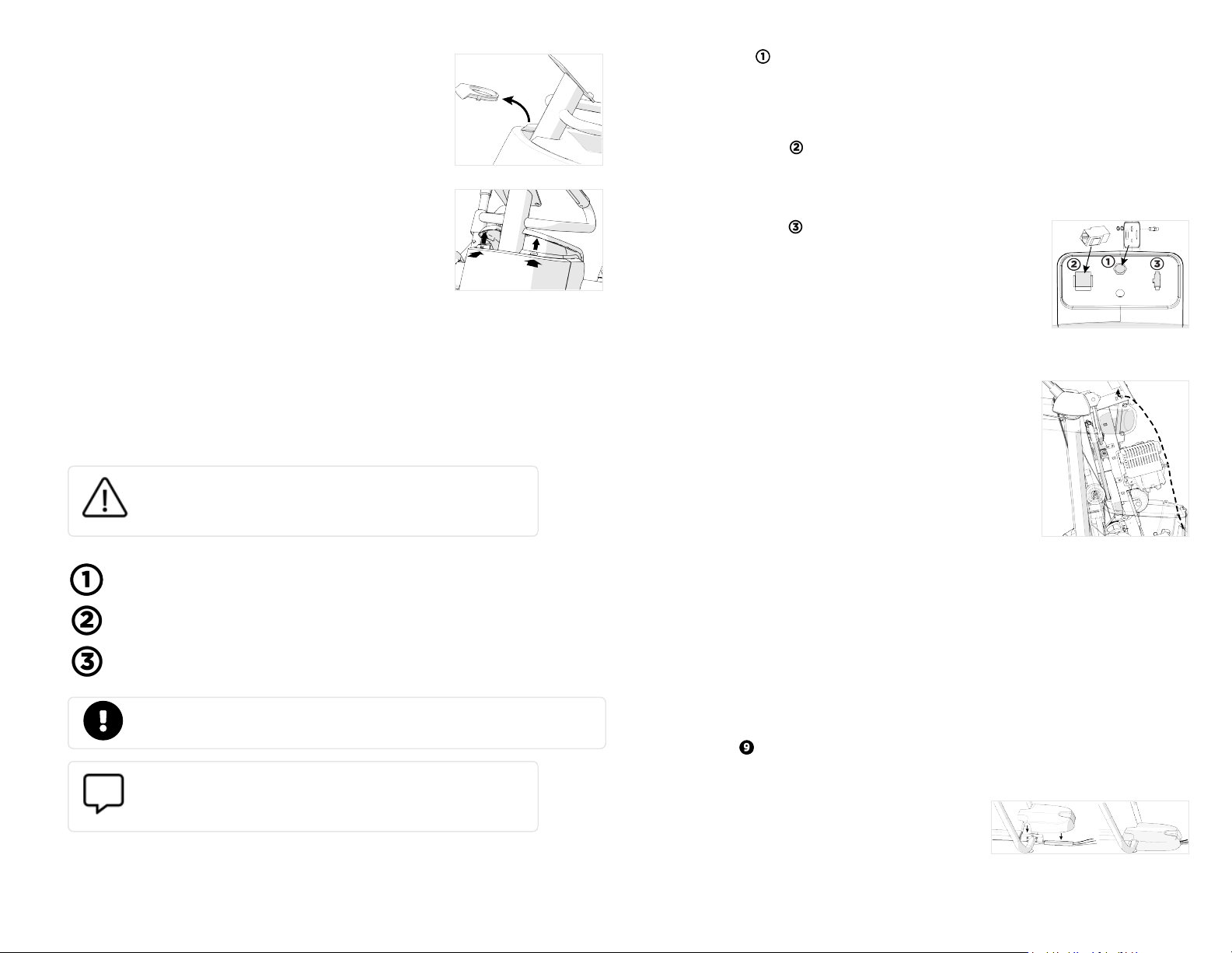
NOTE In the following steps, pass the console power cable through
the opening first, followed by the TV cable. Pass the remaining
cables through in order of connector size (Figure 11).
Thread the cables for each part as follows:
1. TV connection
a. Install the TV (coax) coupler, star washer, and nut, into the jack plate at the lower
end of the AMT and tighten (Figure 11).
b. Connect the TV cable to the inside end of the TV cable coupler. Tighten the
connector using a 7/16-inch open-end wrench.
2. Ethernet connection
a. Attach the Ethernet coupler into the jack plate at the lower front of the AMT (Figure
11).
b. Plug the Ethernet cable into the coupler.
3. Console connection
a. Plug the console power cable into the jack plate (Figure
11).
b. Slide the quick-disconnect terminal on the grounding lead
of the power cable over the grounding terminal on the
equipment frame.
Figure 11
Continue the wiring
1. Pass the ends of all cables through the opening in the top of
the cable channel and secure them in the cable clips.
2. Route cables through the cable clips next to the front flywheel,
through the topmost cable clip on the main frame, and up to
the center support (Figure 12).
3. Remove the tie from the base data cable. Group that cable
with the others and thread them upward through the center
support and out through the center opening in the console
mount, making sure that the heart rate sensor cable extends
out of the opening as well.
4. To complete the console installation, refer to the installation
guide that came with the console.
Figure 12
IMPORTANT Store excess cable inside the center support. DO NOT allow cables to hang loosely
inside the body of the AMT.
Route cables under rear pedestal (optional)
When the AMT faces away from the cable raceway, use the conduit included in the hardware kit
to route the Ethernet, TV, and power cables underneath the center of the AMT and through its
rear pedestal.
To use conduit
1. Lay out the cables so that they pass directly under the center support of the AMT and place
the conduit on the floor directly behind the center support.
2. Insert the cables, one at a time, into the slot at the top of the conduit. IMPORTANT DO
NOT clip or tie the segments of the cables that you insert into the conduit.
3. Lower the rear pedestal over the back frame tube and
the side arm supports. The pedestal should sit flat on
the floor and with the conduit completely inside of it
(Figure 13).
Figure 13
©2020 Precor Incorporated |Adaptive Motion Trainer (AMT) Assembly Guide 304438-101 rev D, ENU | October 23, 2020| 3