weight tower frame.
Note: The end of the guide rod with the screw hole in it should face up. Also, you may need to
loosen the set screws in the retaining ring to seat the guide rod completely.
2. Slide the 160 mm support tube onto the guide rod from the top down.
3. Slide the support ring onto the guide rod, followed by the rubber bumper.
4. Slide the 7.5 lb (3.5 kg) add-on weight onto the guide rod, making sure that the groove is at
the top end of the weight.
5. Attach the top of the guide rod to the bracket at the top of the weight tower frame using:
1 – M10 x 25 mm hex head bolt
1 – 11 mm flat washer
6. Fully tighten the M8 set screw in the retaining ring using the S4 hex key.
Tighten all frame mounting hardware
Figure 6
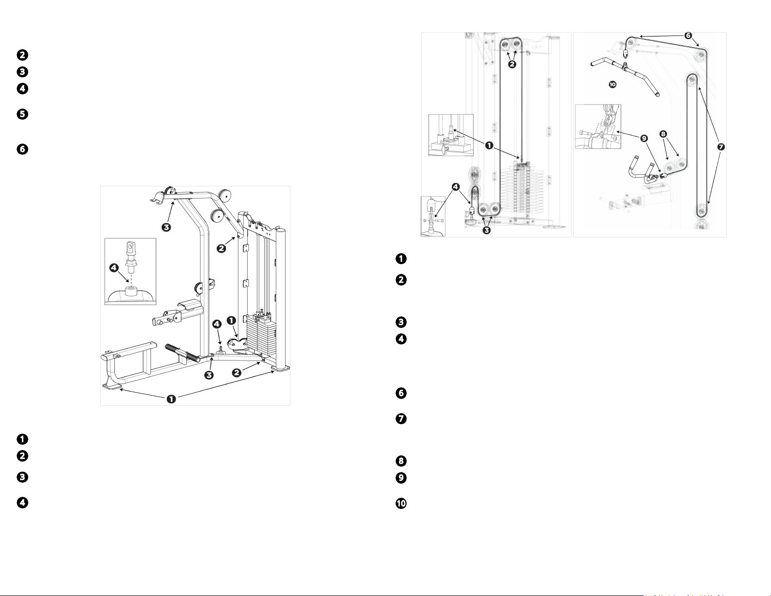
1. Check that the weight tower and seat frame are sitting evenly on the floor.
2. On the weight tower, tighten the mounting hardware at the seat frame, then at the move-
ment arm.
3. On the upright support, tighten the mounting hardware at the seat frame, then at the move-
ment arm.
4. Screw the cable anchor into its fitting on the base frame so that when the jam nut is
tightened, between three and five (3–5) threads remain visible.
Route the cable
Figure 7
1. If the weight stack cable is not attached to the weight stack stem, screw one end of the cable
into the top of the weight stack stem.
2. Pull the cable through the top of the weight tower frame, over the top of the dual pulleys,
and under the cable retaining brackets. Thread the cable down through the tower frame.
Important: In the following step, make sure the cable passes between the fingers on both
sides of the pulley bracket.
3. At the bottom of the weight tower frame, thread the cable through the lower pulley bracket.
4. Thread the cable over one of the pulleys on the dual floating pulley assembly, then attach the
end of the cable to the fixed bracket on the base frame.
5. Remove the cable anchor fitting from one end of the movement arm cable.
Important: In the following step, make sure the cable passes between the fingers of the pulley
bracket at the front of the movement arm.
6. Thread the cable through the pulley at the front of the movement arm, then through the pul-
ley at the upper back of the movement arm, and down to the floating pulley assembly.
7. Thread the cable around the upper pulley in the floating pulley assembly, then up to the pul-
ley at the lower back of the movement arm.
Important: In the following step, make sure the cable passes between the fingers of the front
pulley bracket in the center of the support arm.
8. Thread the cable down and around the two pulleys in the center of the support arm.
9. Reassemble the cable anchor fitting as shown in Figure 7, attaching the row handle to the
carabiner clip at the end of the cable. Rest the row handle on the protective plate.
10. Attach the pulldown bar to the upper end of the movement arm cable using a carabiner clip.
©2021 Precor Incorporated |VSL Pulldown/Seated Row|Assembly Guide |P/N CWR267777-102 ENU 31 July 2021 |3