Experience™ Series 800 Line Climber (CLM) Assembly Guide
Follow the steps in the order listed in this assembly guide. For more product information,
visit us at www.precor.com.
WARNING At least two people are required to assemble the equipment. DO
NOT attempt assembly by yourself.
Assembly requirements
Important
Before you fully tighten a fastener, check that its head is flush with the surface of
the equipment. If not, cross-threading may have occurred. DO NOT attempt to rework the
assembly as more damage to the equipment will occur. Instead, contact Customer Support at
www. precor.com
We recommend you:
Assemble the equipment close to where you plan to use it.
Assemble the equipment on a solid, flat surface, so that it remains level and stable.
Locate the equipment at least 19.7 inches (0.5 meter) away from walls or furniture
on either side of the equipment, and 19.7 inches (0.5 meter) away from objects
behind or in front of the equipment.
DO NOT move the equipment without assistance.
Required tools Hardware kit
Phillips screwdriver
2-inch wrench
(open-end or box-end)
SAE standard socket set
Standard set of hex keys
Fish tape (optional)
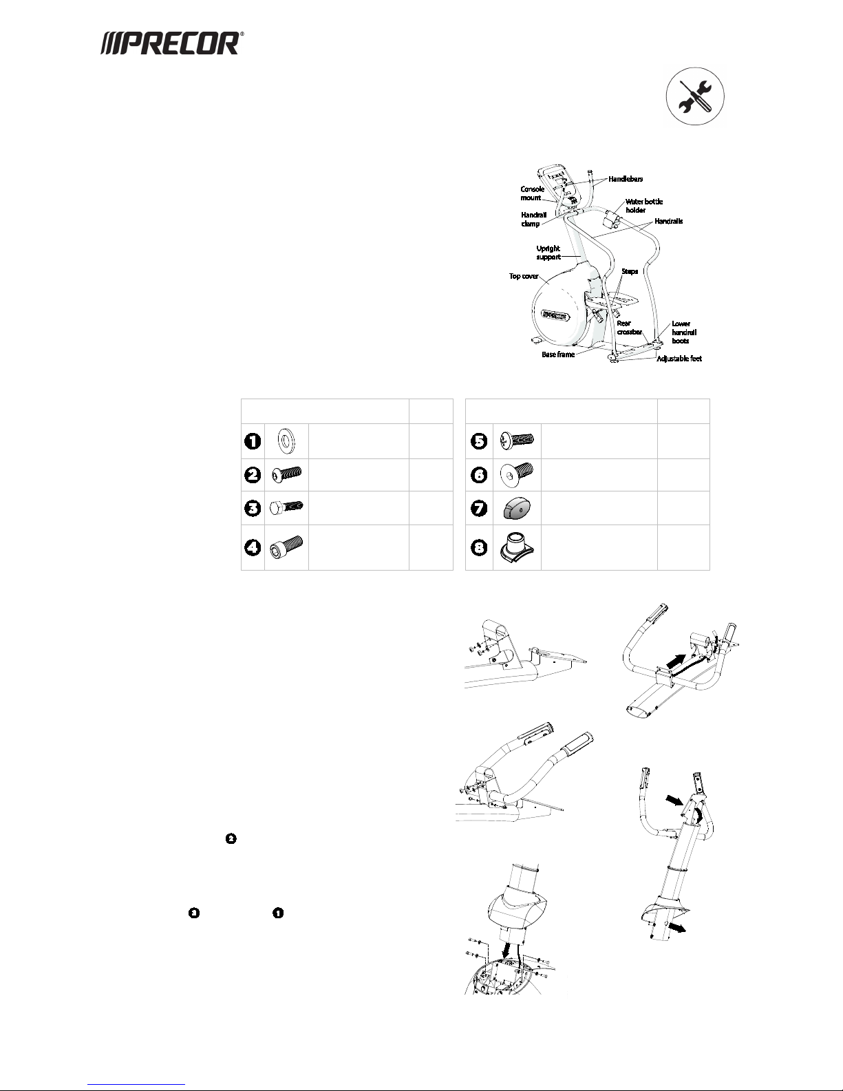
Component Quantity Component Quantity
Washer
(5/16-inch) 4
Phillips-head screw
(3/4-inch) 3
Button head screw
(1/2-inch) 6
Flat head hex drive screw
(1/4-inch x 5/8-inch) 4
Hex head screw
(1-inch) 4 End cap 2
Socket head cap screw
(1 1/4-inch) 2
Handrail boot 2
DANGER DO NOT attempt to connect electrical power until all
assembly procedures are complete and the console is
properly installed.
Do not stretch, crimp, or damage the cables. Cables damaged by improper
installation.
A fish tape can be helpful during this procedure.
To assemble the climber:
1. Remove the two hex nuts and washers that secure the handrail clamp (see Figure 1).
2. While your assistant holds the handlebar near the console mount, feed the heart rate
sensor cable and data cable through the opening in the upright support.
3. Pull them through the top of the support and through the opening in the console
mount. Place excess cable inside the upright support.
4. Insert the handlebar flange onto the screws protruding through the handrail clamp and
rotate the handlebar to align it with the side screw holes (see Figure 2).
CAUTION Hold the handlebar upright until it is securely fastened in
Step5.
5. Secure the handlebars with the two bolts and washer (previously removed) and then
fully tighten the two screws to secure the handlebars (see Figure 3).
6. Slide the top cover onto the upright support (see Figure 4).
7. Using the cable assembly from the console box, feed the cables through the opening in
the console mount, then down through the upright support, and out through the
opening in the lower back of the support (see Figure 4).
8. Ask your assistant to hold the upright support while you attach it to the base frame
using four screws and four washers (see Figure 5). Fully tighten the
fasteners in an alternating order using a 2-inch wrench.
Figure 1
Figure 3
Figure 5


