PremierOne 70550 User manual

Automatic Poultry Door
Puerta automática para gallineros
EN Operating instructions
ES Indstrucciones de uso
#70550-US-PR
#540257-P1S
Premier1Supplies.com

2

3
EN Operating instructions for controller. . . . . . . . . . . . . . . . . . . . . . 4
A. Document information . . . . . . . . . . . . . . . . . . . . . . . . . . . . . . . . . . . . . . . . 4
B. Product information. . . . . . . . . . . . . . . . . . . . . . . . . . . . . . . . . . . . . . . . . .4
C. Important safety instructions. . . . . . . . . . . . . . . . . . . . . . . . . . . . . . . . . . . . . 4
D. Installation instructions . . . . . . . . . . . . . . . . . . . . . . . . . . . . . . . . . . . . . . . 5
1. Supplied package . . . . . . . . . . . . . . . . . . . . . . . . . . . . . . . . . . . . . . . . . . . . . . . . . . . . . . . . . . .5
2. Setup of the device . . . . . . . . . . . . . . . . . . . . . . . . . . . . . . . . . . . . . . . . . . . . . . . . . . . . . . . . . .5
3. Installation . . . . . . . . . . . . . . . . . . . . . . . . . . . . . . . . . . . . . . . . . . . . . . . . . . . . . . . . . . . . . .5
E. Operating instructions . . . . . . . . . . . . . . . . . . . . . . . . . . . . . . . . . . . . . . . . 7
1. Bringing into operation . . . . . . . . . . . . . . . . . . . . . . . . . . . . . . . . . . . . . . . . . . . . . . . . . . . . . . . .7
2. Operation . . . . . . . . . . . . . . . . . . . . . . . . . . . . . . . . . . . . . . . . . . . . . . . . . . . . . . . . . . . . . . .7
3. Errors and possible solutions. . . . . . . . . . . . . . . . . . . . . . . . . . . . . . . . . . . . . . . . . . . . . . . . . . . . . .9
F. User-maintenance instructions . . . . . . . . . . . . . . . . . . . . . . . . . . . . . . . . . . . . 9
1. Cleaning / maintenance . . . . . . . . . . . . . . . . . . . . . . . . . . . . . . . . . . . . . . . . . . . . . . . . . . . . . . . .9
2. Maintenance and repair . . . . . . . . . . . . . . . . . . . . . . . . . . . . . . . . . . . . . . . . . . . . . . . . . . . . . . . .9
3. Technical data. . . . . . . . . . . . . . . . . . . . . . . . . . . . . . . . . . . . . . . . . . . . . . . . . . . . . . . . . . . . .9
4. Accessories / replacement articles . . . . . . . . . . . . . . . . . . . . . . . . . . . . . . . . . . . . . . . . . . . . . . . . . . .9
ES Instrucciones de uso . . . . . . . . . . . . . . . . . . . . . . . . . . . . . 10
A. Información sobre el documento . . . . . . . . . . . . . . . . . . . . . . . . . . . . . . . . . . 10
B. Información sobre el producto . . . . . . . . . . . . . . . . . . . . . . . . . . . . . . . . . . . 10
C. Instrucciones de seguridad importantes . . . . . . . . . . . . . . . . . . . . . . . . . . . . . . 10
D. Instrucciones de instalación . . . . . . . . . . . . . . . . . . . . . . . . . . . . . . . . . . . . 11
1. Paquete suministrado . . . . . . . . . . . . . . . . . . . . . . . . . . . . . . . . . . . . . . . . . . . . . . . . . . . . . . . . 11
2. Estructura del dispositivo . . . . . . . . . . . . . . . . . . . . . . . . . . . . . . . . . . . . . . . . . . . . . . . . . . . . . . 11
3. Instalación . . . . . . . . . . . . . . . . . . . . . . . . . . . . . . . . . . . . . . . . . . . . . . . . . . . . . . . . . . . . . 11
E. Instrucciones de uso . . . . . . . . . . . . . . . . . . . . . . . . . . . . . . . . . . . . . . . . 13
1. Puesta en funcionamiento . . . . . . . . . . . . . . . . . . . . . . . . . . . . . . . . . . . . . . . . . . . . . . . . . . . . . .13
2. Funcionamiento. . . . . . . . . . . . . . . . . . . . . . . . . . . . . . . . . . . . . . . . . . . . . . . . . . . . . . . . . . .14
3. Errores y posibles soluciones. . . . . . . . . . . . . . . . . . . . . . . . . . . . . . . . . . . . . . . . . . . . . . . . . . . . .15
F. Instrucciones de mantenimiento para el usuario . . . . . . . . . . . . . . . . . . . . . . . . . . 15
1. Limpieza y mantenimiento . . . . . . . . . . . . . . . . . . . . . . . . . . . . . . . . . . . . . . . . . . . . . . . . . . . . . 15
2. Mantenimiento y reparación . . . . . . . . . . . . . . . . . . . . . . . . . . . . . . . . . . . . . . . . . . . . . . . . . . . . .15
3. Datos técnicos . . . . . . . . . . . . . . . . . . . . . . . . . . . . . . . . . . . . . . . . . . . . . . . . . . . . . . . . . . . 16
4. Accesorios y artículos de repuesto . . . . . . . . . . . . . . . . . . . . . . . . . . . . . . . . . . . . . . . . . . . . . . . . . . 16
Operating instructions for door . . . . . . . . . . . . . . . . . . . . . . . . . . 17
4
EN Operating instructions
A. DOCUMENT INFORMATION
The manufacturer reserves the right to make changes due to technical developments in the data and images given in this manual.
Reproductions, translations and copies of any kind, including extracts, require written authorization from the manufacturer.
This manual is supplied with the product.
• They should be kept close at hand and remain with the equipment even if the equipment is sold.
• This manual is not subject to an amendment service. The most recent version of this manual can be obtained at any time through
the technical dealer or directly from the manufacturer.
B. PRODUCT INFORMATION
The automatic chicken door opens and closes the entrance to poultry and chicken coops via a cable pull. Optional vertical sliders (ref. no. 70560, 70570)
may be used to change path of pull. The operated slider is automatically opened and closed when the right level of brightness is reached, or at a pre-set time.
Designed for use with poultry, the Automatic Poultry Door is not intended for use with any other type of animal. In the event of incorrect use or modifications
to the device, the manufacturer's warranty and liabilities shall be deemed invalid.
FOR HOUSEHOLD USE ONLY.
C. IMPORTANT SAFETY INSTRUCTIONS
• Read all the instructions before using the Automatic Poultry Door.
• To reduce the risk of injury, close supervision is necessary when the door is used near children.
• Do not come in contact moving parts.
• Only use attachments recommended or sold by the manufacturer, especially the doorplates for automatic chicken door.
• Do not use outdoors without additional protection such as a roof. Do not install the power supply adaptor outdoors.
• Do not unplug by pulling on the cord. To unplug, grasp the plug, not the cord.
• Unplug from outlet and disconnect battery when not in use and before cleaning or service.
• Do not operate any appliance with a damaged cord or plug, after the appliance malfunctions or has been dropped/damaged in any manner. Return
appliance to the dealer or the nearest service facility for examination, repair or electrical or mechanical adjustment.
• Do not put the whole device in water or other liquid. Do not place or store appliance where it can fall or be pulled into a tub or sink.
Danger!
• Do not extend the pull cord.
• The impact of force from the pull cord can cause injury to humans and animals.
• Incorrect setup can create hazardous zones for humans or animals.
• The power pack is not protected against moisture. Only plug the power pack into a socket that is located in a dry and protected area.
• Route the cable to the automatic chicken door with protection so that the animals are unable to reach it.
Warning!
• If the device is supplied with power from the power pack, the battery is not used. However, you should replace the battery at regular intervals. Otherwise
there is a risk of battery leakage. Spent batteries and the device itself should be disposed of properly without delay.
• SAVE THESE INSTRUCTIONS
5
D. INSTALLATION INSTRUCTIONS
1. Supplied package
• control unit
• 100-240 Volt mains adapter
• batteries (4 x AA, already in the device)
• light sensor
• pulleys (4)
• installation accessories
• operating instructions
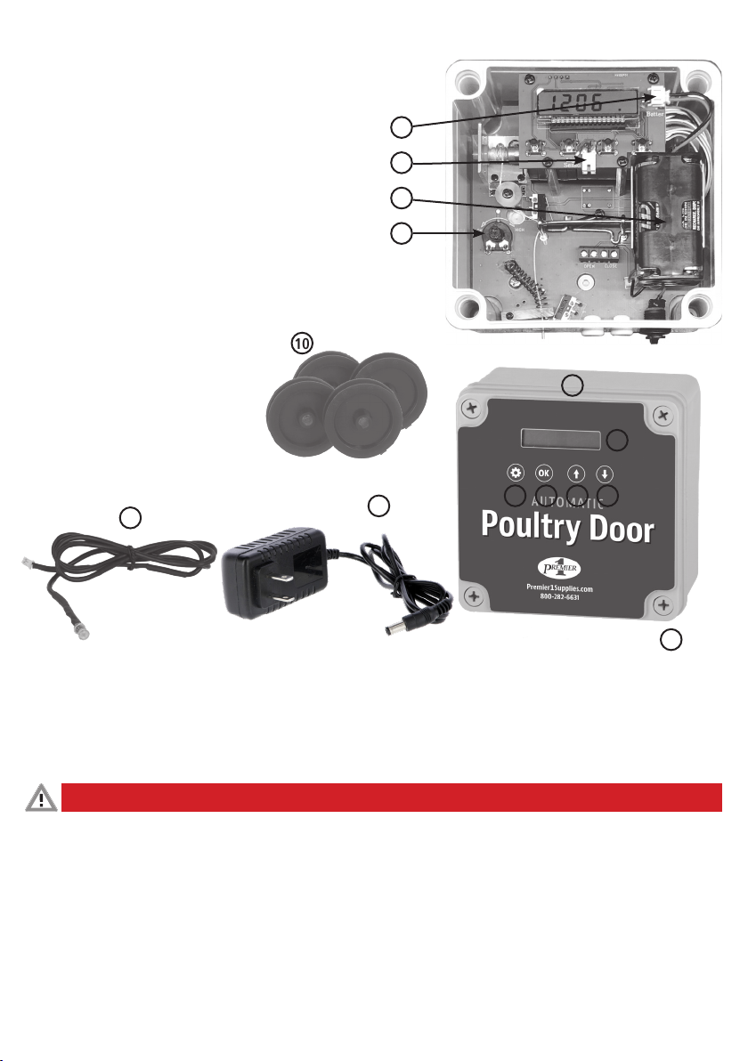
2. Setup of the device
The device consists of the following components:
1) Electronics unit
2) Display
3) Menu button
4) OK button
5) Up button
6) Down button
7) Pull cord for slider
8) Mains adapter
9) Light sensor
10) Pulley for pull cord (optional)
11) Battery connection
12) Battery holder
13) Light sensor adjustment wheel
14) Light sensor connection
3. Installation
3.1 Preparations
Plan the installation site and in particular, the routing of the cord from the door to the device. Measure the opening of the chicken door and provide a suitable
door with guide rails. Get all of the components ready. You will find suitable sliders and additional pulleys in our accessories range. If you wish to supply the
automatic chicken door with mains voltage (110v plug-in), ensure that a mains socket is available near the installation site.
3.2 Suitable installation site and installation conditions
Danger!
Risk of physical injury and material damage if used incorrectly!
• Do not manually extend the pull cord.
• The impact of force from the pull cord can cause injury to humans and animals.
• Incorrect setup can create hazardous zones for humans or animals.
• The power pack is not protected against moisture. Only plug the power pack into a socket that is located in a dry and protected area.
2
3 4 5 6
8
11
12
9
13
14
7
10
1

6
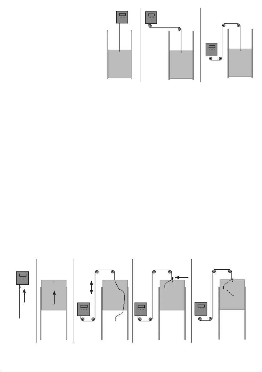
For the automatic chicken door's electronics unit; find an
installation site with a level and stable base. Be aware that
when the slider is opened, a higher load is exerted on the
device than its weight alone. The installation site must be
protected from the ingress of rain.
If necessary, use optional pulleys to guide the cord toward
the door opening. The illustration shows a number of setup
options. The electronics unit is always installed in an upright
position with the cord outlet on the underside.
The slider or the first pulley must be installed so that the cord
is straight when it exits the device. The device or
the last pulley must be installed so that the slider is pulled
straight upwards.
3.3 Attaching the sliding door and electronics unit
1) Attach the door, e.g. to one of the sliders available in our range (Art. 70560, Art. 70570).
Then ensure that the following requirements are met:
• The door weighs a maximum of 5.5 lbs.
• The door moves in a vertical direction and is placed in the closed position by gravity.
• The door moves easily. No great amount of force is required to open the door. When the door is released, it closes independently and reliably. If
necessary, use a few drops of oil to lubricate the sliding surfaces.
• The pull cord must be routed unhindered from the door to the device without contacting foreign bodies.
• The guide rails of the door are precision-installed so that the door closes the opening of the coop reliably.
• The distance from door to building wall should not exceed 0.2 in. throughout the door‘s entire movement path. When the door is closed, the top
opening should have a minimal gap between door and building. Otherwise an animal may be caught and injured if it gets a part of it caught between
the door and building during opening.
• The device, all pulleys and the door are on the same flat plane. The cord will then not chafe against the pulleys‘ sides.
• Install pulleys so they can all be turned without a high degree of resistance.
2) Securely fasten the electronics unit.
3.4 Connecting the pull cord
Proceed as follows (see also the following sketch):
1. Press the “Up“ button to move the cord to the upper terminal position.
The cord will roll into the electronics unit until the knotted end stops at the housing.
2. Move the door to fully open. Leave a little distance (min. 2 in.) between the door and motor housing so that motor has time to switch off before any excess
load develops.
3. Connect the cord to the door so that the door is in the open position when the cord is taut.
4. Knot the cord.
5. Finally, using a pair of scissors, cut off the excess length of the cord.
1 2 3 4 5
7
Month Day
E. OPERATING INSTRUCTION
1. Bringing into operation
Danger!
Risk of physical injury and material damage if used incorrectly!
• Installations on the mains network (110v outlet) must only be carried out by qualified electricians.
• Route the electrical cable to the automatic chicken door with protection so that the animals are unable to reach it.
• If the device is supplied with power from the power pack, the battery is not used. However, you should replace the battery at regular intervals. Otherwise
there is a risk that the battery may leak. Spent batteries and the device itself should be disposed of properly without delay.
• Close the housing before connecting the mains plug to the socket! Always disconnect the mains plug from the socket if you are opening
the housing (for example also if you want to insert the light sensor).
Warning
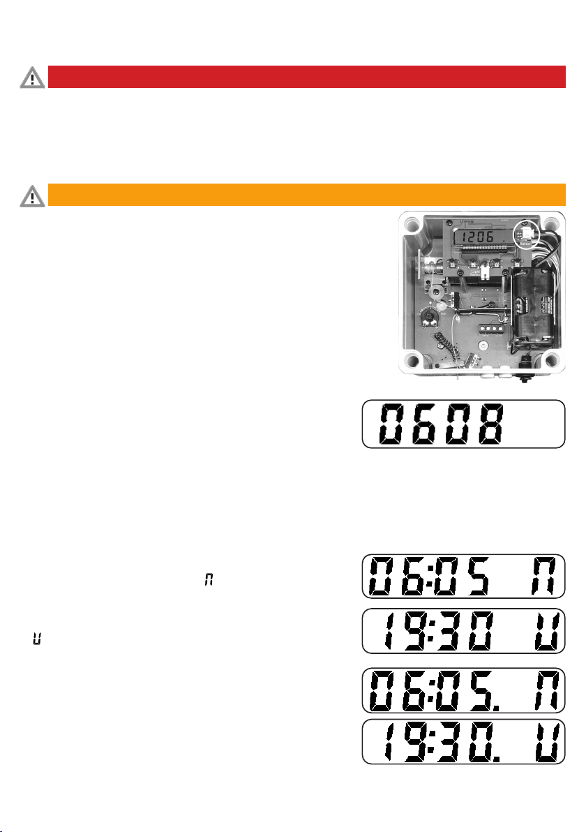
To supply the device with the power it requires, connect either the power pack to the device and
plug it into a mains socket or insert the battery into the device. You can also choose both supply
methods to be prepared for a power failure. The batteries are already installed inside the device.
Connect battery connection wires to the corresponding plug.
Open and close the door a few times to ensure it is operating smoothly. You can now make the
relevant settings, as described below.
2. Operation
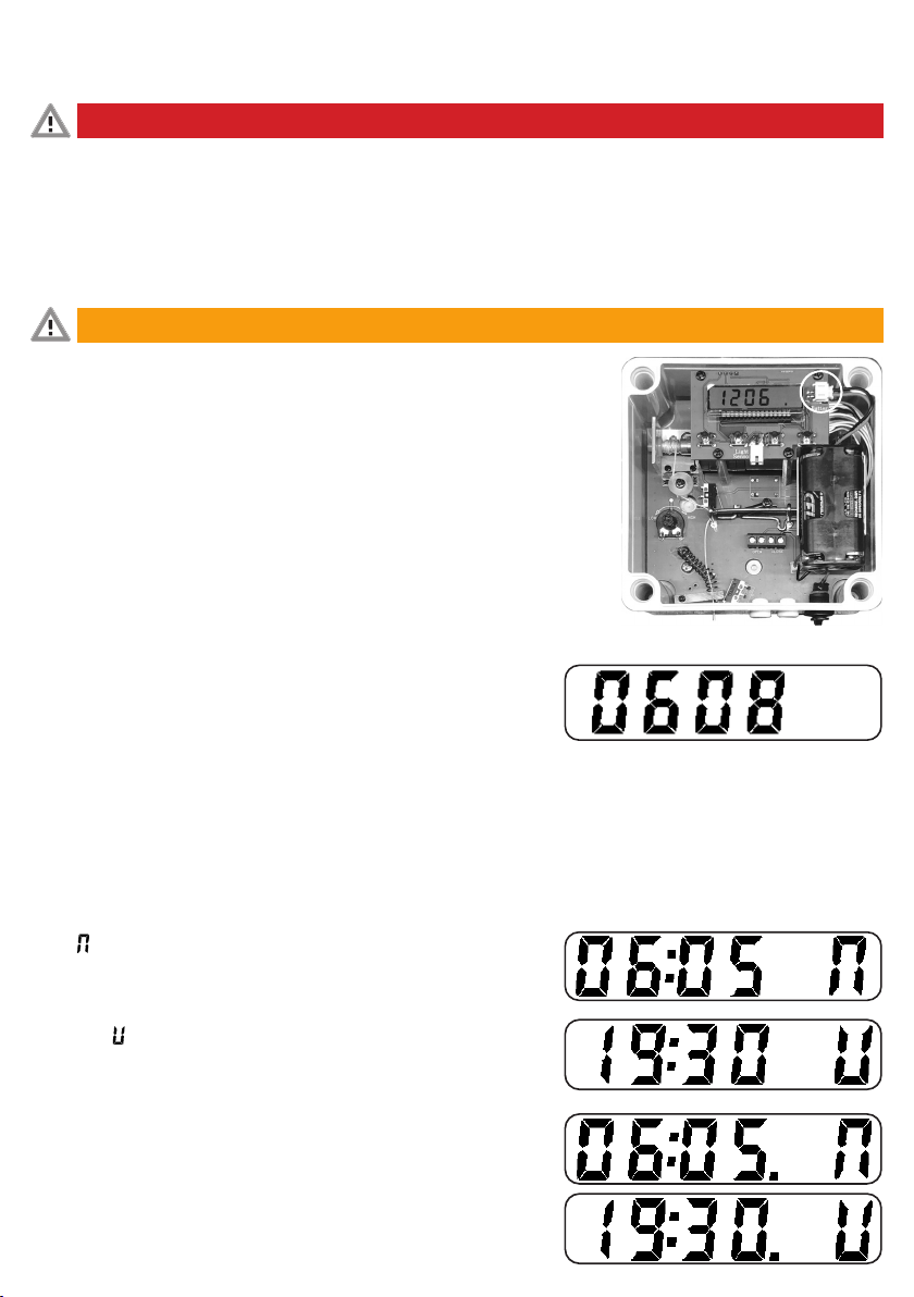
2.1 Time setting
To set the current date and time, press the OK button for 3-4 seconds. The current (set) year starts
to flash. Change the value using the arrow buttons and confirm the year setting with the OK
button. The date then flashes with the month and day.
Change the value of the date using the arrow buttons. The example shown is 8th of June.
The next confirmation takes you to the setting for the current time.
Change the value of the time using the arrow buttons. Exit the Settings menu with the Menu button.
2.2 Automatic opening and closing with the timer switch
You can set an opening and closing time for week days (Monday - Friday) and weekends
(Saturday + Sunday). Please note that the door will
only open or close at the specified times if automatic mode is active.
2.2.1 Setting the opening and closing times
To set the times, press the Menu button for 3-4 seconds. The opening time for the weekday
setting appears. The opening time is indicated by the symbol on the right side of the
display. Use the arrow buttons to select your desired opening time and confirm the input with
the OK button.
The closing time for weekdays setting then appears. The closing time is indicated by
the symbol on the right side of the display. Use the arrow buttons to select your desired
closing time and confirm the input with the OK button.
The weekend opening time setting appears, followed by the weekend closing time setting.
The times for the weekend can be identified by a dot at the end of the time.
8
22:00
02:00 12:00
13) Light sensor
adjustment wheel
Open Close
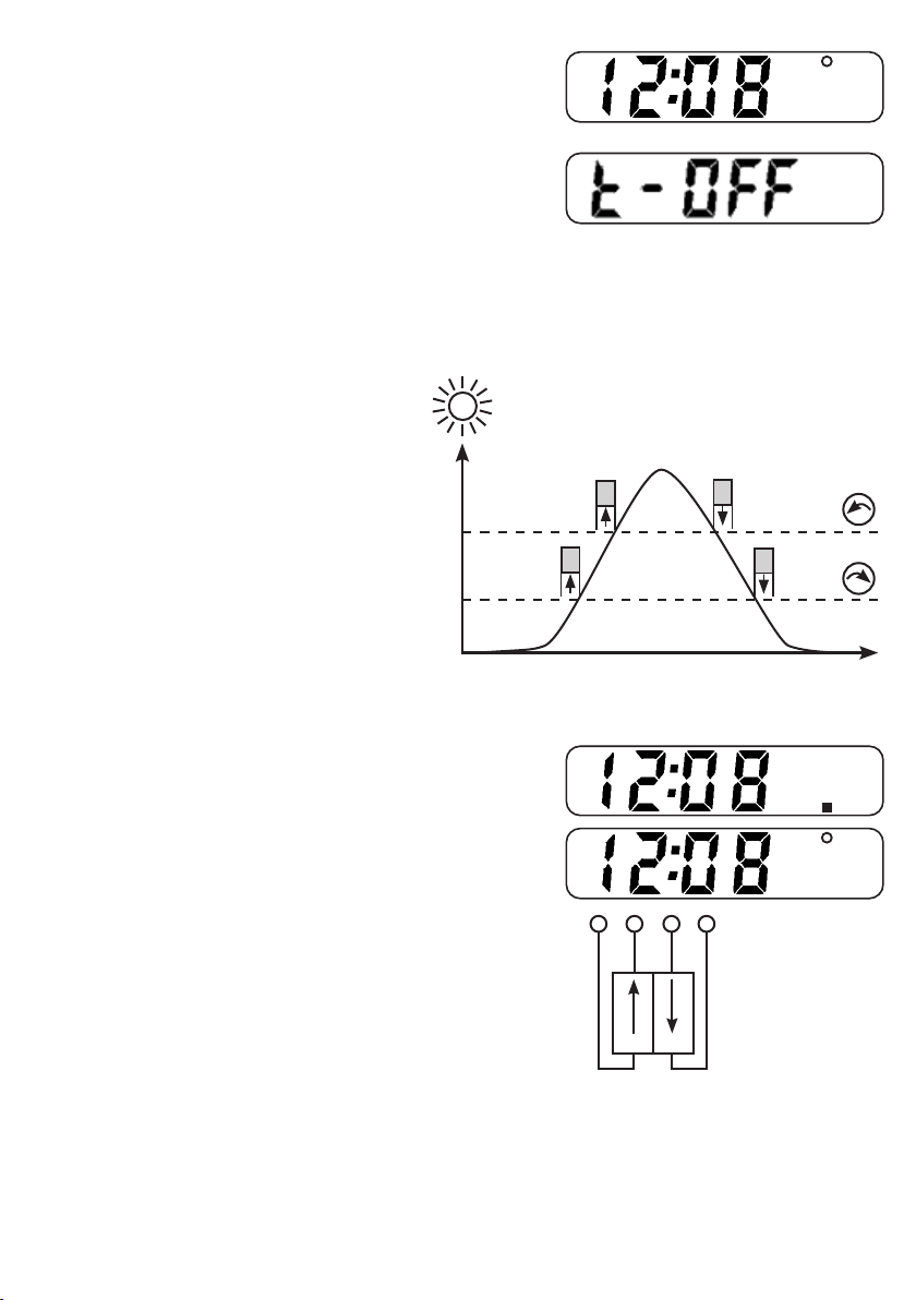
14) Connecting terminals
for external buttons
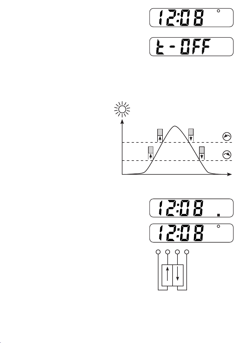
2.2.2 Activating automatic mode
To activate the automatic mode, press the Up key when the door is open or the Down key when
the door is closed. Automatic mode is indicated by a small empty circle at the top side of the
display.
2.2.3 Deactivating the timer
If you want to operate the automatic mode with the light sensor only (see section E 2.3), then you
can deactivate the timer by pressing the menu and OK button at the same time. The display will
show ‘t-off’. Repeat this process if you want to reactivate the timer.
The display will then show the current time.
2.3 Using the light sensor
To make automatic opening and closing dependent on ambient light, connect the supplied light sensor to the device and position the sensor in a suitable
place. Ensure that the sensor is easily able to detect daylight. The sensor must not be influenced by other sources of light (e.g. artificial light from a street
lamp or from a house window). Do not position the sensor on roadways where light from the headlights of passing cars may influence the sensor. Please note
that approx. one minute may elapse before the light sensor responds to a change in brightness. This prevents accidental opening of the door in the event of
lightning.
If automatic mode is activated, the door is opened and closed when the
preset brightness level is reached. The opening and closing times of the
timer (see section E 2.2) remain active even when using the light sensor.
The following applies:
• If the set closing time is reached, the door is always closed
even if the light sensor still detects sufficient brightness.
• If the set opening time is reached, the door will remain closed until the
light sensor has detected sufficient brightness.
You can adjust the sensor‘s switching threshold using the adjustment
wheel in the device. The further you turn the adjustment wheel to the
left, the later in the morning or earlier in the evening the door closes.
2.4 Manual operation
Use the Up and Down buttons to open and close the door manually.
Important: As soon as a manual operation is initiated, the device is in manual mode. Automatic
operations are then no longer carried out.
Manual mode is indicated in the display by a solid square dot on the underside.
Automatic mode can be re-initialised by pressing the Up button again while the door
is open or the Down button while the door is closed. Automatic mode is indicated in
the display by a small empty circle at the top.
2.5 Switching the device off
To switch off the device, disconnect the connecting cable from the socket
and remove the batteries.

9
3. Errors and possible solutions
Error pattern Possible cause Solution
Door does not open and close de-
pending on the time
Timer is deactivated (time does not advance on
the display and ‘t-off’ is shown)
Hold down menu button and OK button
at the same time for 5 seconds
The light sensor prevents the door opening as it is still
dark. (closed state always has priority)
Unplug the light sensor or set the light sensor correctly
Automatic mode is not set
(automatic mode is indicated by a small circle
at the top side of the display)
• press arrow upwards when door is open
• press arrow downwards when door is closed
Door does not open and close de-
pending on the light sensor
Light sensor is not set properly A middle position should be set (depending on desired
dimming) on the dial. Slowly test where the ideal set-
ting is beginning from the middle position.
Automatic mode is not retrieved
(automatic mode is indicated by a small circle
at the top side of the display)
• press arrow upwards when door is open
• press arrow downwards when door is closed
Door does not move down Too little weight on the rope, either because
• the door is too light or
• the door is jammed and does not move down
• use other door/slider
• align guide rails
• use lubrication
• add weight to door
Door does not fully move up and
always remains stationary, or door
does not fully move down and
always remains stationary
Door is obstructed, making it difficult to move
(for example: Dirt in the guide rail)
Door must be smooth-running.
• remove dirt
• align guide rails
• use lubrication
• add weight to door
Door moves at the wrong times Current time set incorrectly Time correctly set in the menu
Opening and closing times not set for weekends The correct times must be set in the menu for
both week days and weekends
F. USER-MAINTENANCE INSTRUCTIONS
1. Cleaning / maintenance
Danger!
Risk of physical injury and material damage if used incorrectly!
• Before starting any cleaning work, disconnect the mains plug.
Check the ease of door operation frequently (at least weekly). Clean the guide rails and use lubricant if necessary. Remove dirt and any objects from the door‘s
closing area in order to protect the motor and avoid transporting dirt via the cord into the inside of the electronics unit. Regularly check the condition of the
cord for wear and replace it in good time. Use our replacement cord to do this (ref.no. 70552).
2. Maintenance and repair
The device does not require maintenance, but should be thoroughly cleaned at regular intervals. In the event of a fault, the device must be taken out of use
immediately. If a repair is required, please contact a qualified electrician or send the device for repair to the manufacturer. A faulty connecting cable should
also only be replaced by the manufacturer or a qualified electrician. Only use original spare parts. If a battery symbol appears on the display, the batteries must
be replaced. After replacing the batteries, the time and date must be re-set.
3. Technical data
Mains voltage 100-240 Volt / 50/60 Hz
Batteries 4 x type AA
min. slider weight 1.1 lbs
max. slider weight 5.5 lbs
External buttons A normally open contact each for Up and Down
Power pack protection class II
Device protection class III
Power pack protection type IPX0
Device protection type IP33
4. Accessories / replacement articles
Réf.no. 70560 Sliding door 220 x 330 mm, incl. guide rails
Réf.no. 70570 Sliding door 300 x 400 mm, incl. guide rails
Réf.no. 70551 Pulleys, pack of 4
Réf.no. 70552 Replacement cord with bead
Accessories and replacement articles must be ordered separately.
FOR HOUSEHOLD USE ONLY.
10
ES Instrucciones de uso
A. INFORMACIÓN SOBRE EL DOCUMENTO
El fabricante se reserva el derecho a realizar modificaciones en los datos y las imágenes recogidos en este manual en virtud de los desarrollos técnicos que
se implementen. Se requiere la autorización por escrito del fabricante en caso de reproducción, traducción o copia de cualquier tipo del presente manual de
instrucciones, incluyendo extractos del mismo. El presente manual se entrega junto con el producto que describe.
• Deberá conservarse en un lugar que esté al alcance de la mano y permanecer junto con el equipo incluso si este se vende.
• El presente manual no está sujeto a un servicio de corrección. En cualquier momento podrá obtenerse la versión más reciente del presente manual a través
del distribuidor técnico o directamente del fabricante.
B. INFORMACIÓN SOBRE EL PRODUCTO
La puerta automática para gallineros abre y cierra correderas verticales —disponibles opcionalmente— (núm. ref. 70560, 70570) en gallineros; para ello,
se emplea un cable de tracción. El entorno correcto para utilizar la puerta automática para gallineros es allí donde se críen aves; por lo tanto, no está prevista
para usarse con cualquier otro tipo de animal. La corredera se abre y cierra automáticamente cuando se alcanza un determinado nivel de luminosidad o a una
hora establecida. En el supuesto de utilizar el dispositivo incorrectamente o realizar modificaciones
en el mismo, la prestación de garantía y las responsabilidades del fabricante se considerarán nulas.
PREVISTO ÚNICAMENTE PARA USO DOMÉSTICO.
C. INSTRUCCIONES DE SEGURIDAD IMPORTANTES
• Lea todas las instrucciones antes de utilizar el aparato.
• Para reducir el riesgo de lesiones, el aparato deberá supervisarse con especial atención cuando se utilice cerca de niños.
• No entre en contacto con piezas móviles.
• Utilice únicamente accesorios recomendados o vendidos por el fabricante, en particular las chapas para la puerta automática para gallineros.
• No lo utilice en exteriores sin contar con una protección adicional como, por ejemplo, un techo protector. No utilice el adaptador de corriente eléctrica en
exteriores.
• No lo desenchufe tirando del cable. Para desenchufarlo, agarre el enchufe, no el cable.
• Desenchúfelo de la toma de corriente y desconecte la pila cuando no lo esté utilizando y antes de realizar tareas de mantenimiento o limpieza.
• No utilice ningún aparato que tenga un cable o enchufe dañado ni después de que el aparato presente un mal funcionamiento, se caiga o sufra daños de
cualquier tipo. Devuelva el aparato al distribuidor o llévelo a las instalaciones de mantenimiento más cercanas para que sea examinado o reparado, o para
reajustar sus componentes eléctricos o mecánicos.
• No sumerja el dispositivo en agua ni en cualquier otro líquido. No coloque ni guarde el aparato en lugares donde pueda caer o tirarse a una bañera o un
lavabo.
¡Peligro!
• No alargue la cuerda de tracción.
• El efecto de la fuerza ejercida por la cuerda de tracción puede provocar lesiones en personas y animales.
• Una instalación incorrecta puede crear zonas peligrosas para las personas y los animales.
• La batería no está protegida frente a la humedad. Conecte la batería únicamente a una toma de corriente que esté ubicada en una zona
seca y protegida.
• Tienda el cable hasta la puerta automática para gallineros; para ello, protéjalo, de manera que los animales no puedan alcanzarlo.
¡Advertencia!
• No se utiliza la pila si el dispositivo recibe alimentación eléctrica de la batería; no obstante, la pila debería sustituirse periódicamente, ya que, de lo
contrario, existe riesgo de que se produzcan fugas en la misma. Tanto las pilas gastadas como el dispositivo deben desecharse adecuadamente y sin
demora.
• GUARDE ESTAS INSTRUCCIONES

11
D. INSTRUCCIONES DE INSTALACIÓN
1. Paquete suministrado
• Unidad de control
• Adaptador de red eléctrica de 100-240 voltios
• Pilas (4x AA: se entregan ya instaladas en el dispositivo)
• Sensor de luz
• Poleas (4)
• Accesorios de instalación
• Instrucciones de uso
2. Estructura del dispositivo
El dispositivo está compuesto por los siguientes elementos:
1) Unidad electrónica
2) Pantalla
3) Botón de menús
4) Botón "Aceptar"
5) Botón "Arriba"
6) Botón "Abajo"
7) Cuerda de tracción para la corredera
8) Adaptador de red eléctrica
9) Sensor de luz
10) Polea para la cuerda de tracción (opcional)
11) Conexión de pilas
12) Soporte de pilas
13) Rueda de ajuste del sensor de luz
14) Conexión del sensor de luz
3. Instalación
3.1 Preparativos
Planifique el lugar de la instalación y, en particular, el tendido de la cuerda desde la puerta hasta el dispositivo. Mida la abertura de la puerta para gallineros
y tenga a mano una puerta adecuada provista de raíles guía. Tenga listos todos los componentes. Encontrará correderas adecuadas y poleas adicionales en
nuestra gama de accesorios (a este respecto, consulte el apartado 12). Si quiere que la puerta automática para gallineros disponga de alimentación por red
eléctrica, asegúrese de que esté disponible una toma de corriente de red eléctrica cerca del lugar de la instalación.
3.2 Lugar y condiciones de instalación adecuados
¡Peligro!
¡Existe peligro de lesiones físicas y daños materiales si el producto se usa incorrectamente!
• No alargue la cuerda de tracción.
• El efecto de la fuerza ejercida por la cuerda de tracción puede provocar lesiones en personas y animales.
• Una instalación incorrecta puede crear zonas peligrosas para las personas y los animales.
• La batería no está protegida frente a la humedad. Conecte la batería únicamente a una toma de corriente que esté ubicada en una zona
seca y protegida.
Encuentre un lugar de instalación provisto de una base estable y nivelada para la unidad electrónica de la puerta automática para gallineros. Tenga en cuenta
que, cuando se abre la corredera, sobre el dispositivo se ejerce una carga mayor que su propio peso. Asimismo, el lugar de la instalación debe protegerse
para que no penetre agua de lluvia.
2
3 4 5 6
8
11
12
9
13
14
7
10
1
12
1 2 3 4
5
En caso necesario, utilice las poleas para guiar la cuerda
moviendo la unidad electrónica ligeramente hacia la abertura
de la puerta. La ilustración muestra una serie de opciones
de instalación; la unidad electrónica siempre se instala en
posición vertical, con la salida de la cuerda ubicada en la
parte inferior.
La corredera o la primera polea debe instalarse de manera
que la cuerda quede recta cuando sale del dispositivo. El
dispositivo o la última polea debe instalarse de manera que se
tire de la corredera directamente hacia arriba.
3.3 Fijación de la corredera y la unidad
electrónica
1) Fije la puerta a, por ejemplo, una de las correderas de nuestra gama de productos (art. 70560, art. 70570).
A continuación, asegúrese de que se cumplen los siguientes requisitos:
• la corredera pesa 2,5 kg como máximo;
• la corredera se desplaza en dirección vertical y se coloca en la posición de cierre por efecto de la gravedad;
• la corredera se desplaza fácilmente. No se requiere mucha fuerza para abrir la corredera, y cuando esta se suelta, se cierra de una manera fiable e
independiente. En caso necesario, aplique unas cuantas gotas de aceite;
• la cuerda de tracción puede tenderse sin obstáculos desde la puerta hasta el dispositivo sin rozarse contra cuerpos extraños;
• los raíles guía de la corredera se instalan con precisión, de manera que la corredera cierre la abertura del gallinero de una manera fiable;
• la distancia desde la corredera hasta la pared de la edificación no es superior a 5 mm a lo largo de todo el tramo que recorre la corredera mientras se
abre. Cuando se cierra la corredera, la abertura de la edificación deja de estar abierta en la parte superior; de lo contrario, existiría el riesgo de aplastar
partes del cuerpo cuando se tira de la corredera hacia arriba;
• el dispositivo, todas las poleas y la corredera están ubicadas al mismo nivel; de esta manera, la cuerda no rozará contra el límite lateral
de las poleas;
• todas las poleas pueden girarse sin que exista un nivel alto de resistencia.
2) Fije la unidad electrónica.
3.4 Conexión de la cuerda de tracción
Conecte la cuerda de tracción a la corredera; para ello, proceda como se describe a continuación (consulte también el esquema mostrado
más abajo):
1. En primer lugar, desplace los componentes electrónicos hasta la posición superior final; para ello, pulse el botón "Arriba".
La cuerda se enrolla en la unidad electrónica hasta que el nudo de la parada final llega a la carcasa.
2. Desplace la corredera hasta la posición superior final (corredera totalmente abierta). Deje un poco de distancia (mín. 50 mm) entre los posibles topes u
obstáculos de la corredera para la posición superior final, de manera que el motor disponga de tiempo suficiente para apagarse antes de que se acumule
una carga excesiva.
3. Conecte la cuerda a la corredera de manera que esta última se encuentre en la posición superior final cuando la cuerda esté tensa.
4. Anude la cuerda.
5. Por último, utilice unas tijeras para cortar el exceso de cuerda.
5
13
E. INSTRUCCIONES DE USO
1. Puesta en funcionamiento
¡Peligro!
¡Existe peligro de lesiones físicas y daños materiales si el producto se usa incorrectamente!
• Las instalaciones en la red eléctrica solo deben ser realizadas por electricistas cualificados.
• Tienda el cable hasta la puerta automática para gallineros; para ello, protéjalo, de manera que los animales no puedan alcanzarlo.
• No se utiliza la pila si el dispositivo recibe alimentación eléctrica de la batería; no obstante, la pila debería sustituirse periódicamente,
ya que, de lo contrario, existe riesgo de que se produzcan fugas en la misma. Tanto las pilas gastadas como el dispositivo deben desecharse
adecuadamente y sin demora.
• ¡En primer lugar, cierre la carcasa antes de conectar el enchufe de red eléctrica a la toma de corriente! Siempre desconecte el enchufe de
red de la toma de corriente si está abriendo la carcasa (por ejemplo, incluso si va a insertar el sensor de luz).
¡Advertencia!
• No se utiliza la pila si el dispositivo recibe alimentación eléctrica de la batería; no obstante,
la pila debería sustituirse periódicamente, ya que, de lo contrario, existe riesgo de que se produzcan fugas
en la misma. Tanto las pilas gastadas como el dispositivo deben desecharse adecuadamente y sin demora.
Para suministrar energía al dispositivo, conecte la batería al dispositivo y enchúfelo a la toma de corriente
o inserte la pila en el dispositivo. También puede optar por ambos métodos de alimentación eléctrica para
estar preparado ante un fallo de alimentación; las pilas ya vienen instaladas en el interior del dispositivo.
Conecte los cables de conexión de las pilas al enchufe correspondiente.
Abra y cierre la puerta unas cuantas veces para asegurarse de que funciona bien.
Ahora podrá realizar los ajustes necesarios tal y como se describe más abajo.
2. Funcionamiento
2.1 Ajuste de la hora
Para ajustar la fecha y hora actuales, pulse el botón "Aceptar" durante unos 3 segundos; el año
establecido actualmente empezará a parpadear. Cambie el valor utilizando los botones de
dirección y confirme el ajuste del año pulsando el botón "Aceptar"; a continuación, la fecha
parpadeará con el mes y el día. Cambie el valor de la fecha utilizando los botones de dirección;
el ejemplo que se muestra es el 8 de junio.
La siguiente confirmación le llevará al ajuste de la hora actual. Cambie el valor de la hora
utilizando los botones de dirección. Salga del menú de ajustes pulsando el botón de menús.
2.2 Apertura y cierre automáticos con el interruptor del temporizador
Puede establecer una hora de apertura y cierre para los días de la semana (lunes a viernes) y los fines de semana (sábado y domingo).
Tenga en cuenta que la puerta solo se abrirá y cerrará a las horas establecidas si está activado el modo automático.
2.2.1 Ajuste de las horas de apertura y cierre
Para ajustar las horas, pulse el botón de menús durante unos 3 segundos; a continuación,
aparecerá la hora de apertura para los días de la semana. La hora de apertura se indica con el
símbolo , ubicado en la parte derecha de la pantalla. Utilice los botones de dirección para
seleccionar la hora de apertura deseada y confirme los datos introducidos pulsando el botón
"Aceptar".
A continuación, aparecerá la hora de cierre para los días de la semana. La hora de cierre se indica
con el símbolo , ubicado en la parte derecha de la pantalla. Utilice los botones de dirección
para seleccionar la hora de cierre deseada y confirme los datos introducidos pulsando el botón
"Aceptar".
A continuación, aparecerá la hora de apertura establecida para los fines de semana, seguida,
por último, de la hora de cierre establecida para los fines de semana. Las horas para los fines de
semana puede identificarse mediante un punto ubicado al final de la hora.
Mes Día
14
2.2.2 Activación del modo automático
Para activar el modo automático, pulse el botón "Arriba" cuando la puerta esté abierta o el botón
"Abajo" cuando la puerta esté cerrada. El modo automático se indica mediante un círculo vacío
de pequeño tamaño, ubicado en la parte superior de la pantalla.
2.2.3 Desactivación del temporizador
Si quiere utilizar el modo automático únicamente con el sensor de luz (consulte el apartado E
2.3), podrá desactivar el temporizador pulsando al mismo tiempo el botón de menús y el botón
"Aceptar"; la pantalla mostrará "t-off". Repita lo anterior si quiere reactivar el temporizador; la
pantalla mostrará la hora actual.
2.3 Uso del sensor de luz
Si quiere que la apertura y el cierre automáticos dependan de la luminosidad ambiental, conecte el sensor de luz suministrado al dispositivo y coloque el
sensor en un lugar adecuado. Asegúrese de que el sensor sea capaz de detectar fácilmente la luz diurna. Asimismo, el sensor no debe verse afectado por
otras fuentes de luz (por ejemplo, luz artificial proveniente de una farola o de la ventana de una casa). No coloque el sensor en calzadas donde la luz de
los faros de los coches que pasen pueda afectar al sensor. Tenga en cuenta que puede transcurrir un minuto aproximadamente hasta que el sensor de luz
reaccione ante un cambio en la luminosidad; ello sirve para evitar que la puerta se abra por accidente en caso de haber relámpagos.
Si el modo automático está activado, la puerta se abre y cierra cuando se
alcanza el nivel de luminosidad establecido. Las horas de apertura y cierre
del temporizador (consulte el apartado E 2.2) permanecen activas cuando
se utiliza el sensor de luz; a este respecto, se aplica lo siguiente:
• Si se alcanza la hora de cierre establecida, la puerta siempre se
cierra incluso si el sensor de luz aún detecta un nivel de luminosidad
suficiente.
• Si se alcanza la hora de apertura establecida, la puerta permanece
cerrada hasta que el sensor de luz detecte un nivel de luminosidad
suficiente.
Puede ajustar el umbral de conmutación del sensor utilizando la rueda de
ajuste del dispositivo. Cuanto más a la izquierda gire la rueda de ajuste,
más tarde se cerrará la puerta por la mañana o en las primeras horas de
la tarde.
2.4 Funcionamiento manual
Utilice los botones "Arriba" y "Abajo" para abrir y cerrar la puerta manualmente.
Importante: en cuanto se inicia una operación manual, el dispositivo pasa al modo manual;
por lo tanto, dejarán de llevarse a cabo operaciones automáticas.
El modo manual se indica en la pantalla mediante un punto cuadrado relleno,
ubicado en la parte inferior.
El modo automático puede reiniciarse volviendo a pulsar el botón "Arriba" mientras la puerta está
abierta o el botón "Abajo" mientras la puerta está cerrada. El modo automático se indica en la
pantalla mediante un círculo vacío de pequeño tamaño, ubicado en la parte superior.
2.5 Apagado del dispositivo
Para apagar el dispositivo, desconecte el cable de conexión de la toma de corriente y retire las pilas.
22:00
02:00 12:00
13) Rueda de ajuste del
sensor de luz
Open Close
14) Bornes de conexión para
botones externos

15
3. Errores y posibles soluciones
Error Posible causa Solución
La puerta no se abre ni cierra en
función de la hora.
El temporizador está desactivado (la hora no
avanza en la pantalla y se muestra "t-off").
Mantenga presionado el botón de menús y
el botón "Aceptar" al mismo tiempo durante
5 segundos.
El sensor de luz impide que la puerta se abra porque
aún está oscuro (el estado cerrado siempre tiene
prioridad).
Desenchufe el sensor de luz o ajústelo
correctamente.
No se recupera el modo automático (el modo
automático se indica mediante un círculo de
pequeño tamaño, ubicado en la parte superior
de la pantalla).
• pulse la flecha "Arriba" cuando la puerta esté abierta
• pulse la flecha "Abajo" cuando la puerta esté cerrada
La puerta no se abre ni cierra en
función del sensor de luz.
El sensor de luz no está ajustado adecuadamente. Debe ajustarse una posición central (en función
de la atenuación deseada) en la esfera. Pruebe lenta-
mente dónde se encuentra el ajuste ideal
empezando desde la posición central.
No se recupera el modo automático (el modo
automático se indica mediante un círculo de
pequeño tamaño, ubicado en la parte superior
de la pantalla).
• pulse la flecha "Arriba" cuando la puerta esté abierta
• pulse la flecha "Abajo" cuando la puerta esté cerrada
La puerta no se desplaza hacia
abajo.
Hay muy poco peso sobre la cuerda, lo que puede
deberse a dos motivos:
• la puerta es demasiado ligera;
• la puerta está atascada y, por lo tanto,
no se desplaza hacia abajo.
• utilice otra puerta o corredera
• alinee los raíles guía
• utilice un lubricante
• añada peso a la puerta
La puerta no se desplaza totalmente
hacia arriba y siempre se queda fija
en el mismo punto; ola puerta no
se desplaza totalmente hacia abajo
y siempre se queda fija en el mismo
punto.
La puerta está obstruida, por lo que resulta difícil
moverla (por ejemplo, debido a suciedad presente en
el raíl guía).
La puerta debe desplazarse sin dificultad.
• retire la suciedad
• alinee los raíles guía
• utilice un lubricante
• añada peso a la puerta
La puerta se desplaza a horas
incorrectas.
La hora actual está mal establecida. Establezca la hora correcta en el menú.
Las horas de apertura y cierre no están establecidas
para los fines de semana.
Las horas correctas deben establecerse en el menú
tanto para los días de la semana como los fines de
semana.
F. INSTRUCCIONES DE MANTENIMIENTO PARA EL USUARIO
1. Limpieza y mantenimiento
¡Peligro!
¡Existe peligro de lesiones físicas y daños materiales si el producto se usa incorrectamente!
• Antes de empezar con cualquier trabajo de limpieza, desconecte el enchufe de red.
Compruebe que la puerta móvil pueda desplazarse con facilidad en todo momento. Limpie los raíles guía y utilice un lubricante si es necesario. Retire la
suciedad y cualquier objeto de la zona de cierre de la puerta para proteger el motor y evitar que se transporte suciedad desde la cuerda hasta el interior de
la unidad electrónica. Compruebe con regularidad si existe desgaste en la cuerda y cámbiela con suficiente antelación; para ello, utilice nuestra cuerda de
repuesto (núm. ref. 70552).
2. Mantenimiento y reparación
El dispositivo no requiere mantenimiento; no obstante, debe limpiarse a fondo periódicamente. En caso de producirse una avería, el dispositivo debe ponerse
fuera de servicio de inmediato. Si se requiere una reparación, póngase en contacto con un electricista cualificado o envíe el dispositivo al fabricante para
que sea reparado; asimismo, todo cable de conexión defectuoso solo deberá ser sustituido por el fabricante o por un electricista cualificado; para ello, solo
deberán utilizarse piezas de repuesto originales. Las pilas deberán cambiarse si aparece el símbolo de las pilas en la pantalla; tras cambiarlas, deberán
reajustarse la hora y la fecha.

16
3. Datos técnicos
Tensión de la red eléctrica 100-240 voltios; 50/60 Hz
Pilas 4x de tipo AA
Peso mín. de la corredera 0,5 kg
Peso máx. de la corredera 2,5 kg
Botones externos Un contacto de apertura convencional para subir y bajar
Clase de protección de la batería II
Clase de protección del dispositivo III
Grado de protección de la batería IPX0
Grado de protección del dispositivo IP33
PREVISTO ÚNICAMENTE PARA USO DOMÉSTICO.
4. Accesorios y artículos de repuesto
Núm. ref. 70560 Corredera de 220 x 330 mm; con raíles guía incluidos
Núm. ref. 70570 Corredera de 300 x 400 mm; con raíles guía incluidos
Núm. ref. 70551 Poleas; paquete de 4 unidades
Núm. ref. 70552 Cuerda de repuesto con bolita
Los accesorios y los artículos de repuesto deben pedirse por separado.
b
tb th
h
fh
a
a
b
h
A B
(1)
(2)
(3)
1 2
3 4
b
tb th
h
fh
a
a
b
h
A B
(1)
(2)
(3)
1 2
3 4

17
EN Operating instructions for sliding doors
1. General
Please read the instructions carefully and note the regulations and information
they contain before assembling the sliding door. Please keep these operating
instructions in a safe place for later use!
2. Correct use
The sliding door is designed to close a wall opening in a coop building so that
no poultry are able to escape and no dangerous animals are able to enter. The
sliding door is intended for use in combination with the Kerbl control unit (Art.
70550). In the event of incorrect use of the door, the manufacturer‘s warranty
and liabilities shall be deemed invalid.
3. Setup
See Figure 1:
(1) Door plate
(2) Guide rails
(3) Fastening screws (4 pcs)
4. Function
The sliding door is made up of two lateral guide rails and a door plate.
The sliding door is opened and close by moving the plate within the guide rails.
The sliding door is positioned inside or outside an existing opening in the wall.
The wall opening must accordingly not exceed certain maximum dimensions.
5. Assembly
Getting ready
Plan the basic setup of the chicken door. You will also find a control unit (Art. 70550) in
our range for the automatic opening and closing of the door. Measure the opening in the
building wall and ensure that the opening can be completely covered by the door plate
(precise instructions regarding measurements can be found in Section 7). Ensure that the
surface around the wall opening is flat and even. Get all of the components ready.
Drawing
Mark out the four fastening points (see Figure 2) in accordance with the dimen-
sions in Section 7.
To ensure the easy running of the sliding door, please ensure that the
installation surface is flat. See Figure 3.
Fastening
First fasten one of the two guide rails to the wall using the fastening screws.
If the installation situation allows it, you can also secure the second guide rail
and then guide the door plate from above into the guide rails (see Figure 4 A).
If obstacles above the wall opening would prevent the subsequent sliding-in
of the door plate, first push the door plate from the side into the guide rail you
have already fixed in place and then attach the second guide rail (see Figure
4 B).
6. Cleaning / maintenance
Regularly remove dirt from the guide rails and in the opening area of the door in
order to keep it moving easily. Remove dirt in the threshold area of the door in
order ensure complete closure of the door. If necessary, use a few drops of orga-
nic lubricating oil to increase the easy running of the door and to avoid noise.
7. Dimensions
#70560 #70570 #70580
a Hole spacing bottom 219 mm 8,62 ” 299 mm 11,77 ” 429 mm 16,89 ”
b Hole spacing top 233 mm 9,17 ” 313 mm 12,32 ” 443 mm 17,44 “
h Hole spacing vertical 506 mm 19,92 ” 606 mm 23,86 ” 606 mm 23,86 “
tb Width of door plate 220 mm 8,66 ” 300 mm 11,81 ” 430 mm 16,93 “
th Height of door plate 330 mm 12,99 ” 400 mm 15,75 ” 400 mm 15,75 “
fh Minimum free height on
the wall (with full use of
the opening height) Note:
additional space may
be required to attach a
control unit!
620 mm 24,41 ” 760 mm 29,92 ” 750 mm 29,53 “
Maximum width of the
wall opening
190 mm 7,48 ” 270 mm 10,63 ” 400 mm 15,75 “
Maximum height of the
wall opening
290 mm 11,42 ” 360 mm 14,17 ” 350 mm 13,78 “
IT Istruzioni per l‘uso porte scorrevoli
1. Informazioni generali
Prima di montare la porta scorrevole, leggere con attenzione le istruzioni e
attenersi alle indicazioni e avvertenze fornite. Conservare le istruzioni per l‘uso
per ogni utilizzo successivo!
2. Utilizzo conforme
La porta scorrevole è stata messa a punto per chiudere le aperture a parete dei
ricoveri per animali, in modo da evitare l‘uscita dei volatili e l‘ingresso di animali
pericolosi. La porta scorrevole è concepita per essere utilizzata insieme al siste-
ma di controllo Kerbl (Art. 70550). In caso di utilizzo non conforme della porta
decadono i diritti di garanzia e di responsabilità forniti dal costruttore.
3. Struttura
Vedere figura 1:
(1) pannello della porta
(2) guide
(3) viti di fissaggio (4 pezzi)
4. Funzione
La porta scorrevole è composta da due guide laterali e da un pannello. La porta
scorrevole si apre e si chiude spostando il pannello all‘interno delle guide. La
porta scorrevole viene montata dall‘esterno o dall‘interno su di un‘apertura
esistente nella parete. Di conseguenza, l‘apertura a parete non deve superare
determinate dimensioni massime.
5. Montaggio
Operazioni preliminari
Prevedere il montaggio di base della porta per pollame. Nel nostro assortimento
troverete anche un sistema di comando (Art. 70550) per l‘apertura e la chiusura
automatiche della porta. Misurare l‘apertura della parete della struttura e
sincerarsi che possa essere coperta completamente con il pannello della porta
in dotazione (le indicazioni precise sulle dimensioni sono riportate nel paragrafo
7). Sincerarsi che la superficie attorno all‘apertura a parete sia piana e uniforme.
Preparare tutti i componenti.
Marcatura
Marcare i quattro punti di fissaggio (vedere figura 2) a seconda delle dimensioni
riportate nel paragrafo 7.
Per garantire la facilità di scorrimento della porta scorrevole, prestare
attenzione a che la superficie di montaggio sia piana, vedere figura 3.
Fissaggio
Fissare dapprima una delle due guide alla parete con le viti di fissaggio. Se la
situazione di montaggio lo consente, si potrà fissare anche la seconda guida e
inserire quindi il pannello della porta nelle guide dall‘alto (vedere figura 4 A). Se
l‘inserimento a posteriori del pannello della porta viene impedito dalla presenza
di ostacoli, inserire dapprima il pannello della porta di lato nella guida già
fissata, dopodiché fissare la seconda guida (vedere figura 4 B).
6. Pulizia/Manutenzione
Rimuovere regolarmente la sporcizia dalle guide e nella zona di apertura della
porta per mantenerne intatta la facilità di scorrimento. Rimuovere la sporcizia
nella zona della soglia della porta per poterla chiudere completamente.
Utilizzare eventualmente una goccia di olio lubrificante biologico per aumentare
la facilità di scorrimento della porta ed evitare la formazione di rumori.
7. Dimensioni
#70560 #70570 #70580
a Distanza tra i fori in basso 219 mm 8,62 ” 299 mm 11,77 ” 429 mm 16,89 ”
b Distanza tra i fori in alto 233 mm 9,17 ” 313 mm 12,32 ” 443 mm 17,44 “
h Distanza tra i fori in verticale 506 mm 19,92 ” 606 mm 23,86 ” 606 mm 23,86 “
tb Larghezza pannello
della porta
220 mm 8,66 ” 300 mm 11,81 ” 430 mm 16,93 “
th Altezza pannello della porta 330 mm 12,99 ” 400 mm 15,75 ” 400 mm 15,75 “
fh
Altezza libera minima
della parete (se si sfrutta
completamente l'altezza
dell'apertura) Attenzione:
il montaggio del sistema
di comando necessiterà
eventualmente di
ulteriore spazio!
620 mm 24,41 ” 760 mm 29,92 ” 750 mm 29,53 “
Larghezza massima
dell'apertura a parete
190 mm 7,48 ” 270 mm 10,63 ” 400 mm 15,75 “
Altezza massima
dell'apertura a parete
290 mm 11,42 ” 360 mm 14,17 ” 350 mm 13,78 “
b
tb th
h
fh
a
a
b
h
A B
(1)
(2)
(3)
1 2 3 4
See illustrations p. 16

Premier 1 Supplies
2031 300th St.
Washington, IA 52353
Premier1Supplies.com
800-282-6631
This manual suits for next models
1
Table of contents
Languages:
Other PremierOne Farm Equipment manuals

Popular Farm Equipment manuals by other brands


Westfield
Westfield STX2 Series operating manual

FLEMING
FLEMING TOP3 Operator's manual & parts list

CUSTOM PRODUCTS
CUSTOM PRODUCTS CozyCab TORO A-10855 Mounting instructions

MacDon
MacDon 802 Operator's manual

roost&root
roost&root Round-Top Walk-In Coop 2 Assembly instructions

Zipper Mowers
Zipper Mowers ZI-MD300G Operation manual