roost&root Round-Top Walk-In Coop 2 User manual

Fall 2022
Model 2
V1
Shown With Optional Waterer & Feeder
Assembly Instructions
Round-Top Stand-Up Coop™
These written instructions, as
provided with your purchase, will
always be the latest iteration of the
instructions and match the coop
shipped and provide the most
complete up-to-date information.
We depend on feedback about our
instructions to implement changes
to future versions. Please know
that we value your input to that
ongoing process and endeavor to
produce instructions that are as
effective as possible for a wide
variety of customers.
Assembly
Overview...
Use your phones camera to read QR Code.
Video overview of assembly.
Help Text-line: 512-596-5200
EMAIL: [email protected] re: Assembly Support
VOICE: 877-741-2667 | Assembly Support ext 3
Copyright ® Roost & Root all rights reserved. This document is intellectual property of Roost & Root and is being provided to you for your own personal limited use as a
paying customer for the purpose of assembling your coop. Roost & Root claims all available Federal protection for the name Round-Top Coop™, our protected designs and
trade dress as is allowed by any and all Federal intellectual property protection laws. We invest heavily in your coop and work very hard to do a good job and it is only fair that
our workers benefit for their hard work.

Assembly Instructions
Round-Top Stand-Up Coop
Model 2 Fall 2022 V1
Copyright ® Roost & Root all rights reserved.
Orientation
Front
Left
Right
Back (We recommend having the back side of your coop facing North)
Turn Out Door
Optional Feeder
Eaves
Roof Vents
"Egg Box"
"Run"
Open
Wired
Area
"Roost"
Closed Area
Where Birds
Sleep
Optional Waterer

Assembly Instructions
Round-Top Stand-Up Coop
Model 2 Fall 2022 V1
Copyright ® Roost & Root all rights reserved.
Concepts
Sorry... a little reading ;-)
Sealing & Care:
We recommend you leaving your coop natural. You can stain your coop but should only use a "breathable" low VOC water based stain. You can have color added to these
products too...like painting, but it's a wood stain that lets the wood breathe. You paid a premium price for your coop in part to pay for the cedar. It will last outdoors in its
natural state for many years, better than almost any other wood. Sealing can keep the wood from going grey. That's the main benefit. Clean wood with mild detergent and
water or with a commercially available coop cleaner as needed. Glues used in all joints are completely waterproof and all metal parts are galvanized or have exterior rated
coatings.
Placement:
Easy access to water/feed and clear access to doors is needed. Sunlight is not all bad, and the Galvalume roof does a good job at not transferring heat and provides shade.
Sunlight does a good job at disinfecting the ground under the coop. Fifty percent (50%) or more of direct sun is preferred. Good air movement around your coop is more
important than anything else. The proper side should face North if at all possible. Remember... High ground is dry ground. For coop doors to open easily over time, the
coop must be level.
Digging Predators:
The welded wire and cedar frames are stronger than almost any predator less than a bear :) so diggers are the prime nuisance. By far dogs are the most common digger.
Other "wild" animals, while more rare, certainly can dig too. If you’re worried about diggers, stack heavy block shaped rocks around perimeter of coop to make getting under
more difficult. Better yet, bury them around the perimeter just below grade. You can also attach a strip of wire that extends out from the bottom rails, and bury below the
surface of the soil. We recommend dirt in bottom of coops that has good drainage. Pine shavings, straw or shredded junk mail can be used in laying areas... but is not
recommended in the main run areas.
More About Cedar:
Your coop is built from rough cut domestic cedar. Our 2x2's are actually custom milled. Wood deemed defective is culled during milling, cutting and in fabrication... about 5%-
10% does not "make the cut". Knots, blemishes, fraying, coloring variations, minor surface cracking, slight warping and periodic worm marks are normal parts of natural
wood products. We try to make it to where a reversible part always has a “pretty side” and take care to make the “pretty side” show on all parts. If you’re unhappy with a
piece of wood we fabricated into your coop, send us a picture. We want you to love every piece of your new coop.
Understanding these concepts / conventions will help guide you through the instructions.
1 Mating edges of parts to be flush and tight (when called for) will keep measurements in tolerance as the coop grows in size.
2 CRITICAL: Having a flat area is required for the coop to assemble properly and operate properly.
3 We estimate about 8 man hours (1/2 day for 2 people) of ordinary skills to assemble. Two people are required for many steps.
4 You will need a drill (preferably cordless) a tape measure and a hammer. Everything else is provided.
5 Drive screws only deep enough to hold parts tight and not bury the heads too deeply as water can sit in the divots and it may cause
softening of the wood and prematurely loosen screws. It will also greatly decrease your ability to easily disassemble a part if needed.
6 You may end up directly driving in a screw. The provided screws are very aggressive and can drive with no pre-drilled hole or you can
preferably use the provided pilot countersink bit. Keep screw entry points in the meat of the wood and not too close to edges. Screws in
knots or close to edges should for sure be pre-drilled.
7 Rough Cedar may have knots, cracks or frays that are normal. We cull and cut around most imperfections we deem structurally problematic
during fabrication. If you get a piece that you feel is not beautiful, please let us know so we can address your concern.
8 We hand fabricated your coop with human carpenters. We work really hard to not make mistakes. On the rare occasion that we either
misfabricated a part, a part was damaged in shipping, or we forgot to package a needed part, contact us and we will ship out a replacement
part for you at no cost.
9 We recommend dirt floors in the runs of coops. A trimmed rubber mat can be placed in the bottom of egg boxes and you may wish to put
pine shavings or shredded junk mail in them. They are left wire so they can be cleaned in the event of a broken egg.

Assembly Instructions
Round-Top Stand-Up Coop
Model 2 Fall 2022 V1
Copyright ® Roost & Root all rights reserved.
Parts List
Written Parts List
"A" Parts - Exterior
Sides
A1 Left Wired Wall
A2 Right Wired Wall
A5 Left Wood Filled Wall (door)
A6 Right Wood Filled Wall
Front
A7 Left Front (water & feed)
A8 Right Front
A9 Door (with handle & hinges)
Back (as if looking at from front)
A10 Left Back
A11 Right Back (door)
Roof
A21 Arc (identical pair)
A22 Roof Supports (identical pair)
A23 Eave Boards (identical pair)
A24 Roof Metal (3 pc matched set)
"B" Parts - Roost
B1 Roost Bars (4 identical)
B2 Roost Door Panel (door)
B4 Roost Door Storm Panel (translucent panel)
B5 Day Roost Bar
"C" Parts - Egg Box
C1 Egg Box Face (egg shaped holes)
C2 Egg Box Access Panel (2 doors)
C3 Egg Box Floors (2 identical wired panels)
"D" Parts - Storage Area
D1 Storage Area Floor (wood & wire)
D2 Storage Area Door (wire)
D3 Storage Valence Holder Board (slot)
D4 Storage Valence (translucent panel)
D5 Door Storm Panel (translucent panel)
"F" Parts - Accessories (if purchased)
F1 4" EZ-Fill Waterer & 2 Poultry Nipples
F2 Waterer Hanger Bracket
F3 EZ-Fill Feeder
F4 Feeder Retainer Bracket
F5 Storm Panel Set (13 Panel Set)
Tools Provided
T25 & T20 Torx Bits
Phillips Bit
Magnetic Bit Holder
1/8" Drill Bit
Loose Hardware
5 Safety Clips
3 Gravity Gate Latches
2 Sliding Gate Latches
2 Hook & Eye Sets
2 Stake Nails
1 Window Bolt & Screws
Fasteners Provided
3” T25 Screws 171+
1 5/8” T20 Screws 16+
Rubber Washer Roof Screws 20+
Phillips Screws Gate Latches 30+
Pan Head Phillips Screws Sliding Latches 4+
* Extra screws are included
Tools you'll need...
A level (or use your cell phone)
Hammer
3 - 6 Foot
Step Ladder
Tape
Measure
Drill... preferably
a cordless drill
with 2 charged
batteries.

Assembly Instructions
Round-Top Stand-Up Coop
Model 2 Fall 2022 V1
Copyright ® Roost & Root all rights reserved.
Please Be Careful
Some of the steps will need to be performed from a ladder. If you are not
comfortable and experienced standing on and working from a ladder you may
want to get some help for those steps. Please be careful.
Please Be Careful
Any roof metal and flashing can have sharp edges. We attempt to knock off
sharp corners and edges from roof metal. You must be the final determiner of
sharp edges. A standard metal file from your hardware store, or metal snips,
can be used to make edges to your standards. You may choose to wear a
pair of work gloves while handling roof metal.
Be careful not to get caught in coop. Children should not play in coop as
the doors are not designed to allow easy exit.
Spending the time up front to identify all the parts and lay them all out will
pay off in the long run and make assembly go more smoothly. The
instructions are intended to be read in page order as, the information builds
in that way, then referenced during assembly. Pre-reading the instructions
will help immensely.
Coop is designed to be assembled
by two people of ordinary skill.

Assembly Instructions
Round-Top Stand-Up Coop
Model 2 Fall 2022 V1
Copyright ® Roost & Root all rights reserved.
Step 1 - Left & Right
Back Corners
1.1 Left Back Corner: Using the provided T25 Torx Bit in
provided Bit Holder and your drill, drive 6 of the 3" T25
Screws from panel A5 into panel A11 through pre-drilled
holes to form the left back corner of the coop. Panel A5
connects to back side of panel A11. Or said another way,
panel A11 overlaps panel A5.
Note 1: Only drive screws deep enough to be tight and try
not to bury heads too deeply into the wood. Use your drill
on its slow setting.
Note 2: Make bottom edges flush and sides flush as you
put in screws.Work your way up from the bottom.
1.2 Right Back Corner: Repeat the procedure from step
1.1 and attach the A6 right side back panel to the A10
back panel.
1.3 Attach Back Panels Together: Move the left side
back assembly (A5 & A11 panels) into position to join to
the right side assembly (A6 & A10 panels) and using 8 of
the T25 screws join the A11 and A10 panels together
putting screws into pre-drilled holes screwing into
positions as illustrated. Take care to make bottom edges
flush and side flush as you work your way up to join.
1.4 Gravity Gate Latch: Using phillips head screws as
illustrated and provided phillips bit in bit holder, install the
gravity gate latches as illustrated in Fig 1 on the back turn
out door. Remove shipping screw from frame of door
when complete. This same procedure applies to the other
latches.
Pro Tip: Push edges of panels in and out as you work
your way up so that outside face is as flat as possible.
The wood we use is "rough cut exterior grade cedar" so
the dimensions of the lumber will not be precise.
Phillips Screw
:-) Here we go !
= Direction
Of Screws
T25 Torx Bit
3" T25 Screw
Phliips Bit
Bit Holder
Color of screws may vary.
A11
A10
A5
A6
The first step is to assemble the two back panels and two
back side panels as illustrated. Reading this entire step first
before tackling it will help you to better understand what
you're going to be doing.
Find and
remove
shipping
screw
from door
frame.
Left
Side
Back
First
Screw
Bottom Edges
Must Be Flush
Make Edge
Seams Flush
First
Screw
Fig 1
Use Phillips Screws

Assembly Instructions
Round-Top Stand-Up Coop
Model 2 Fall 2022 V1
Copyright ® Roost & Root all rights reserved.
Step 2 - Left & Right
Front Sides
Left Side
Back
2.1 Left A1 Side Panel: The left and the right wired panels are the same. Using 6 T25 screws, attach the front A1 panel to the back section A5 panel made in step 1. Start at the bottom
making sure the bottom edge is flush and work your way up keeping the faces flush by pulling in or out as needed.
2.2 Right A2 Side Panel: Repeat the procedure in 2.1 to attach the A2 right side panel to the A6 back side panel. The coop should sit stable enough now to go onto the next steps.
2.3 Install Gravity Gate Latch: Install gate latch on egg access door using the same procedures as you used before.
Looking like something...
A1
A2
Wire Side
Faces Inward
Make Bottoms
Flush
A5
A6
Front
Keep faces flush
= Direction
Of Screws
3" T25 Screw
Color of screws may vary.
Gravity
Gate
Latch

Assembly Instructions
Round-Top Stand-Up Coop
Model 2 Fall 2022 V1
Copyright ® Roost & Root all rights reserved.
Step 3 - Assemble
Egg Box / Roost
Assembly
Fig 3
3.1 Someone Holding For You: Using T25 screws attach C1 Egg Box Face Panel to middle vertical post of C2 Egg Box Access Door Panel driving screws from C2 middle post into
C1 edge. Now attach D1 Storage Floor on top (wood side up) making sure back edge of C1 is flush with cross piece on D1 wooden area. Screw in from C2 into C1 and from D1 into top
edge of C1.
3.2 Install Egg Box Floors: Using T25 screws attach the lower C3 Egg Box Floor (wire side down) tight into the corner formed from the C2 Panel and C1 Panel attaching from C2 into
C3 edge and C1 into C3 edge. Repeat for upper C3 Floor noting the alignment with C2 and C1 as illustrated in Fig 3 & 3A.
3.3 Install Roost Door: Place B2 Door Panel into place as illustrated making sure edges are flush and attach using T25 screws from positions shown. Some screws are behind door.
Double check that all screws are in and edges are flush.
3.4 Storage Door Window Bolt: Using 4 small Philips head screws included with the Window Bolt, install the bolt portion of the hardware in the center of the D1 panel front (as
illustrated) into the pre-drilled holes. Discard the U-shaped retainer portion of the window bolt.
Fig 4A
:-) Can we get some help here?
Wood Up
Floor Aligned
With Cross
Piece On
Front
Floor Flush With Bottom
Open Door To Access Screw Holes
All Edges Flush
Edges Flush
Align With
Cross
Piece
Fig 3A
Assembled As A Unit
Then Fitted Into Place
In Next Step...
C1 Flush Here
Wire Down
Wire Down
Window
Bolt
B2
C2
D1
C3
C3
C1
C1
= Direction
Of Screws
3" T25 Screw
Color of screws may vary.

Assembly Instructions
Round-Top Stand-Up Coop
Model 2 Fall 2022 V1
Copyright ® Roost & Root all rights reserved.
Step 4 - Install Egg
Box / Roost Assembly
T-20 Screw
(color may vary)
4.1 With Help: Lift the Egg Box Assembly made in Step 3 into coop placing against back wall and resting the unit on top of the boards on the inside of the A5 and A6
Panels. Fig 4. You may need to carefully splay apart sides for unit to fit into place and then carefully move them back to make it squeezed in tightly.
4.2 Attach: Making sure edges of assembly are visually running straight up and down with coop sides, adjusting as needed, drive T25 screws from C2 & B2 panels into sides of coop.
See Fig 4.
4.3: Drive 2 T20 screws through holes indicated in Fig 4A through A10 Panel. these screws go into back side of the C1 Egg Box Face on the other side of the wall.
4.4: Drive 3 T25 screws through holes indicated in Fig 4B left side back edge to support assembly back side. Repeat with 1 T25 screw in Right Side as indicated in Fig 4C.
:-) Now you know why we left the front off at this point...
Fig 4
Fig 4A
Hang Assembly On Boards Inside Panels A5, A6
Fig 4B
(Left)
Fig 4C
(Right)
After this step, the coop will become
very difficult for even two people to
move so you should make sure its
positioned where you want and on
level high ground.
Confirm level along both the back and
the sides. A level app on a smart-phone
works great! Rake out or build up ground
as necessary.
Egg Box Assembly
From Step 3
A5
A6
A10
C2
B2
T20
Bit

Assembly Instructions
Round-Top Stand-Up Coop
Model 2 Fall 2022 V1
Copyright ® Roost & Root all rights reserved.
Step 5 - Front & Back
Arcs
Fig 5
Fig 5A
:-) Find your step ladder again!
26½ Inches
D4 Valance
D3 Valence Holder
D2 Door
A21 Arc
A21 Arc
Attach Same As Previous Steps
Stake
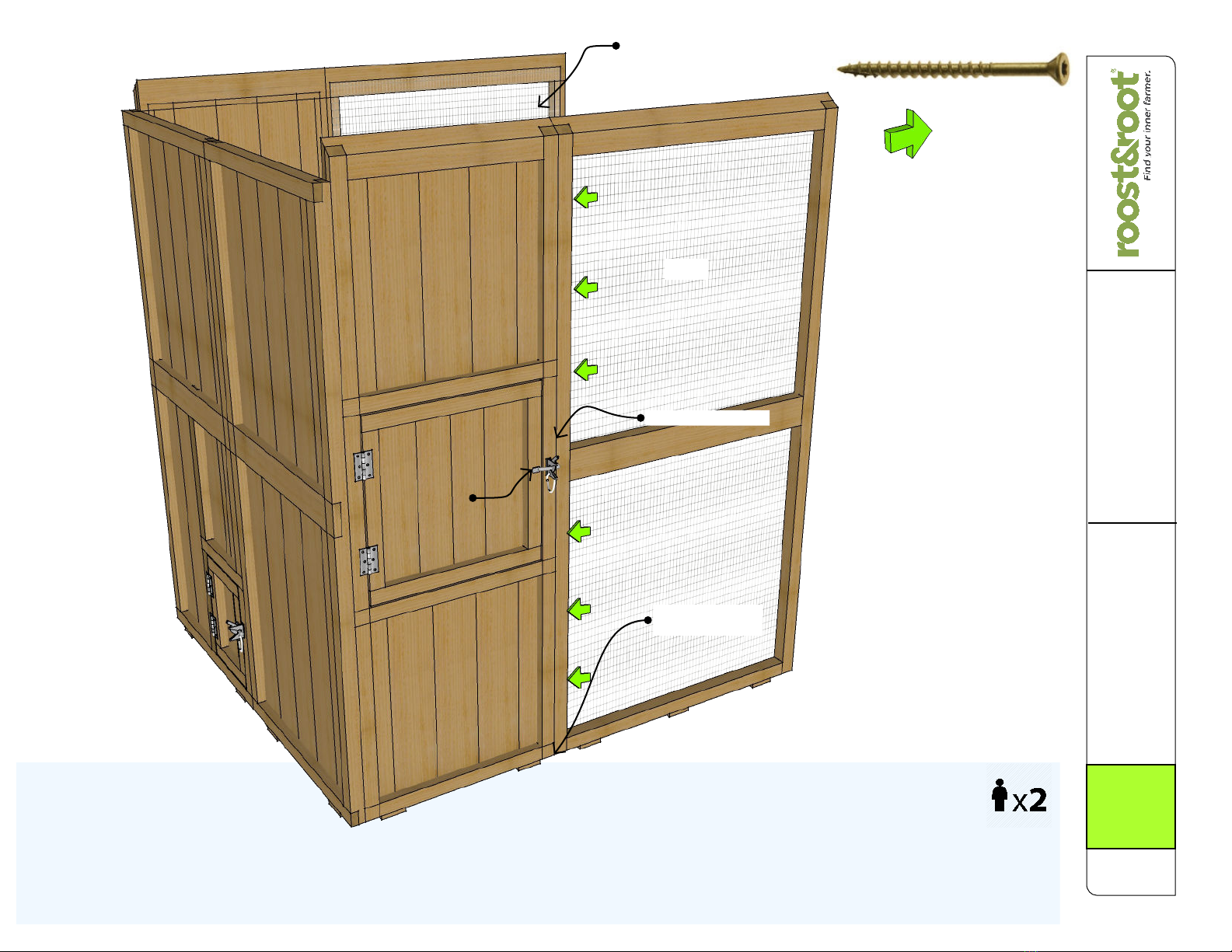
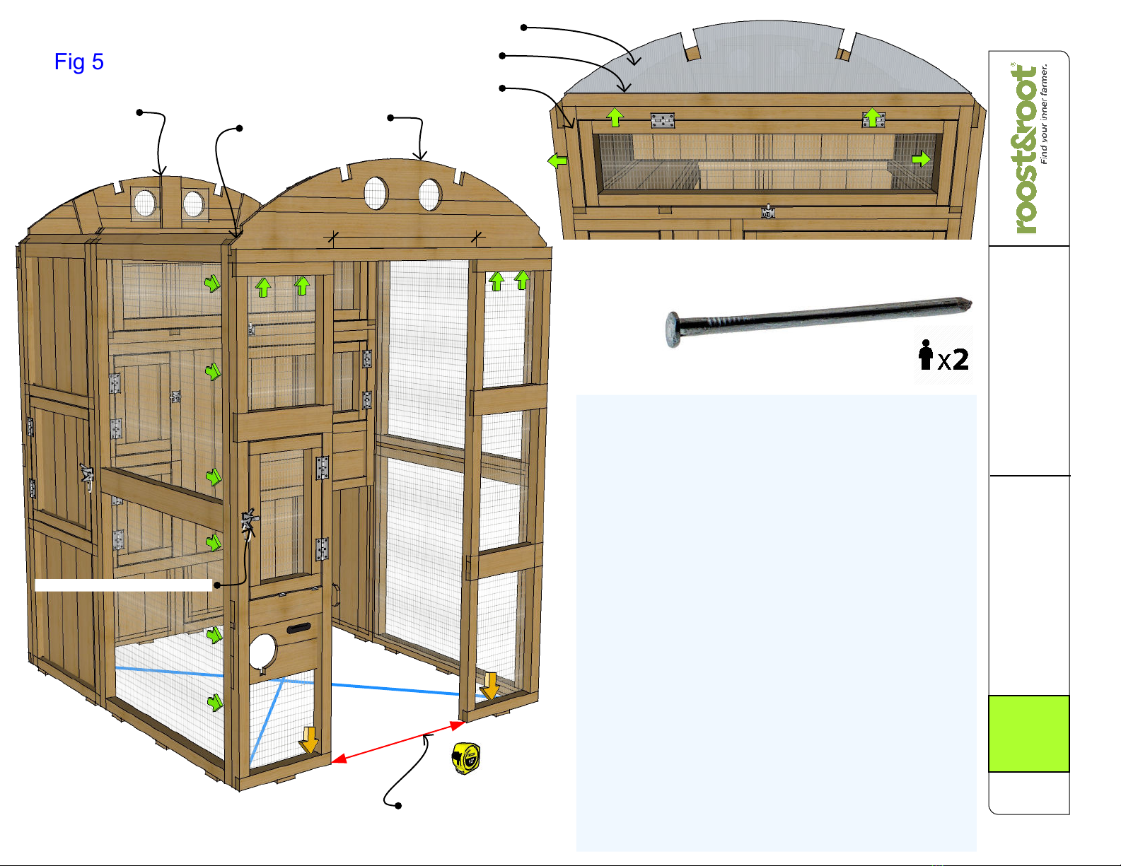
5.1 Attach Left & Right Run Fronts: Using T25 screws into pre-drilled
holes, attach left side A7 and A8 panels as illustrated in Fig 5 making
sure to keep edges and bottom of panels flush. Repeat for right side
Install latch hardware as in previous steps on panel A7.
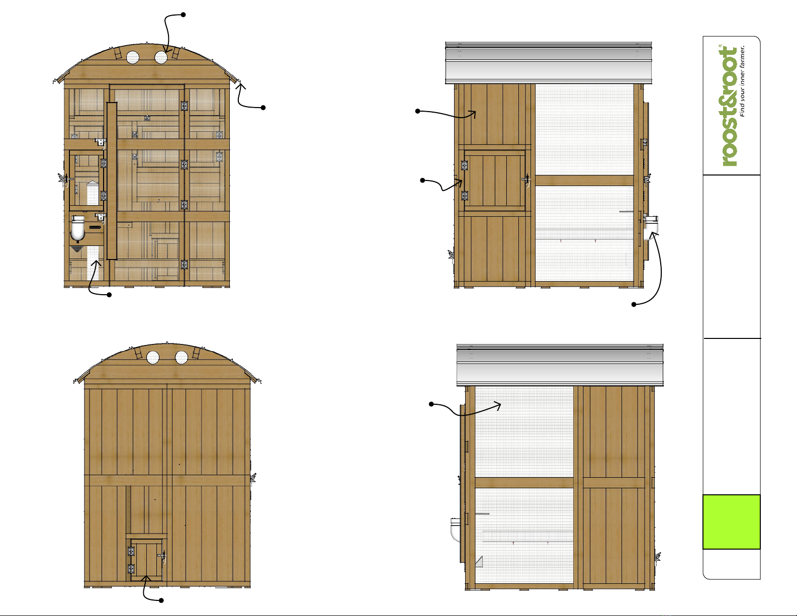
5.2 Front & Back Arcs: Using T25 screws into pre-drilled holes under
top rail of A7 & A8 attach A21 Arc on top of A7 & A8 moving left and
right sides of coop in or out as required to make left, right and front edges
line up. See Fig 5. There should be ~ 26½ inches between left & right
sides. Repeat back A21 Arc on top of A10 & A11 panels driving T25
screws up into bottom rail of Arc from top rail of A10 & A11 panels.
5.3 Square Up Coop: Your coop should be level, but it might be a little
"racked". Using a measuring tape measure the inside dimensions of coop
corner-to-corner as illustrated by the blue lines in FIG 5. It should be
about 83 inches. Most importantly, it should be equal corner-to-corner.
"Rack" the coop corner-to-corner as needed to make the measurement
equal.
5.4 Stake Down Front: Position A7 and A8 Front Panels In/Out to
where there is ~ 26½ inches between left & right sides at ground level.
When correct, drive Stakes through holes in bottoms of A7 & A8 where
indicated by Gold Arrows to stake down the bottom edges of front door
opening. See Fig 5. Make sure front of panels are straight across too.
5.5 Storage Door & Valance: Position D2 Door on top of Storage Area
as indicated in Fig 5A and using T25 screws attach door frame on left
and right sides by aligning with edges of coop and driving screws from
frame into side panels of coop. Place D3 Valance Holder Board on top of
D2 Door Frame aligning side to side and edges, and drive T25 screws up
through D2 Door Frame top edge into bottom of D3. Place D4
CoroClear® Valance Panel into slot of D3.
Flush
Measure Before
Staking Down
A1
A7
A8
26-1/2"

Assembly Instructions
Round-Top Stand-Up Coop
Model 2 Fall 2022 V1
Copyright ® Roost & Root all rights reserved.
Step 6 - Eaves & Roof
Fig 6
Fig 6A
:-) Be careful on that ladder !
~½ inch
~ 2" Overhang On Eave
Edge of Roof
Lower Panel Screw Line
Center Panel Has Screw Holes On Both Edges
Center Panel Screw Line (Lower Panel Upper Edge Gets Pinned Under Center Panel)
A24 (3 Pieces)
A22
A23
3-1/2"
Roof
Screw
Make Sure Your Coop Is Square & Level As Believe It
Or Not :-) The Roof Locks It All In Place...
6.1 Roof Supports: Using your hand, tap into place the two
A22 Roof Supports aligning the notches of the supports
with those in the A21 Arcs. See Fig 6. Fit support into
cutout of CoroClear® D4 Valance installed in previous
step. If notches are too tight to tap with your hand, tap with
hammer directly on top of notches a little at each end at a
time. Be gentle.
6.2 Eave Boards: Using the smaller T-20 Star Bit in the Bit
Holder, attach the A23 Eave Boards as illustrated in Fig 6
using the T-20 Screws in the predrilled holes. Align Eave
Boards with equal amounts extending from each end, about
3½ inches. Double reinforced edge faces down and
towards the bottom.
6.3 Galvalume® Roof: Identify the Center A24 Roof Panel.
Its the one with holes along both edges. Other two Lower
Roof panels are interchangeable.
Lower Panels: Position one of the Lower A24 Roof Panels
along the A23 Eave Board with about 2 inches of the Roof
Panel extending out along the bottom and centered side to
side, about ½ extending out. Top edge of panel along the
A22 Support will help you align. Using the Bit Holder with
no bit in place, put 1 Roof Screw in center hole of the
Lower A24 panel driving through panel into Eave Board to
temporarily hold in place. Repeat for other side.
Center Panels: Carefully place the Center Roof Panel over
the top of the two lower roof panel upper edges pinning the
lower roof panels under the Center Roof Panel and drive
Roof Screws through center panel into A22 Supports
keeping the angle of the Roof Screws more or less along
the same lines as the supports. Do it however you can but
starting in the center and switching back and forth from side
-to-side will result in the most flat panel installation. Repeat
along edges until all screws are in.
Finish Up Lower Panels: If bottom panel is curved nicely
and laying flat, install remainder of E3 screws in other
holes. If it is a little bowed after installing center panel, you
can remove bottom center screw and install other screws
into eaves first, holding flat, and then re-install center screw
once you like it.
A21
Push Eave Boards Up Into Arc Edge
T-20 Screw
(color may vary)
Center Screw
First
Lower Under Center
Screws From Center Out Works Best

Assembly Instructions
Round-Top Stand-Up Coop
Model 2 Fall 2022 V1
Copyright ® Roost & Root all rights reserved.
Step 7 - Door Install
Fig 7
:-) Like, you're pretty much done!
Another set of hands will be helpful...
7.1 Install Door: Your A9 Door Hinges are already
attached to the door and the holes pre-drilled in the right
side panel.
Using 12 Flat Head Phillips Screws attach the A9 Door
hinges to the right side panel in pre-drilled holes snugly
installing top screws of each hinge first, then snugly
installing bottom screws of each hinge, then installing
middle screws of each hinge tight. After everything looks
lined up, go back and tighten tops and bottom screws of
each hinge. Tightening screws in this pattern will help to
keep door aligned.
7.2 Sliding Gate Latch: Position the upper sliding gate
latch as shown in Fig 7 and using the provided Sliding Gate
Latch Pan Head Screws affix the latch using pre-drilled
holes making sure that the latch pin moves freely into the
catch hole on the Door Handle. When aligned, tighten latch
down. Repeat for lower latch.
7.3 Main Door Hook: With hook and eye, install on the
inside of the main door so that you can lock the door behind
you if needed. Works best with the hook on the door and
the eye in the side panel.
A9 Door
Latch
Towards
Top Edge
Latch
Sliding Gate Latch Pan Head Screw
Flat Head
Phillips
Screw
Bit
Door handle
serves as a
stiffener, a
handle and a
door stop.
An extra hook and eye set
is provided if you want to
install inside of coop.

Assembly Instructions
Round-Top Stand-Up Coop
Model 2 Fall 2022 V1
Copyright ® Roost & Root all rights reserved.
Step 8 - Roost Bars
Installation
Fig 8
8.1 Install Roost Bars: Roost panels are hidden so that
you can see locations of roost bars. Using a helper
behind the coop, position B1 Roost Bars in locations
shown in Fig 8 and using T25 Screws on front and back
panels, drive screws into center of bars fixing them into
position.
8.2 Day Roost: Carefully hand tap B5 Day Roost bard
into position as shown in Fig 8. For easy cleaning, it is not
screwed in.
8.3 Storage Door & Main Door Hooks: As noted in Fig 8
attach storage door Eye Hooks in pre-drilled hole on
storage door (standard position) and using the provided
1/8 inch drill bit, make a pilot hole on the roof beam
directly above and install the hook part to your liking.
If you prefer a lower hook point, the hook portion of the
eye can be installed along the storage doors edge and
hooked into the wire on the side panels.
:-) Need that helper again!
Cut-Away View of Roost
B5 Day Roost Bar
B5
H3 Hook & Eye
Pre-Drilled Hole For Eye
Alternate Hook Location
Eye
Hook

Assembly Instructions
Round-Top Stand-Up Coop
Model 2 Fall 2022 V1
Copyright ® Roost & Root all rights reserved.
Step 9 - Waterer &
Feed Brackets
(Option)
Fig 9
9.1 Install Waterer Bracket: If you purchased the optional waterer, install
the F2 Bracket in the position as illustrated in Fig 9 using 2 T25 screws
screwed in up from the bottom of the bracket into the into bottom rail of the
C2 door panel.
9.2 Install Feeder Bracket: If you purchased the optional feeder, install the
F4 Bracket as illustrated in Fig 9B using T20 Screws installed in frame ends
of feeder. Open door to put in screws.
Fig 9A shows the waterer and feeder in place as they are when in service.
:-) Chow time!
Fig 9A
Fig 9B
F2 Waterer Bracket (if purchased)
Installs Up Against Wall Using 2 T25
Screws Through Holes In
Bottom of the Bracket and Into
Door Frame.
Open Door To
Screw Down
9.3 Poultry Nipple Installation
1st install rubber grommet
into holes. Rotate to seat.
2nd force fit by pushing, the nipple
into the grommet. Protect your
hand with a towel if needed.
T-20 Screw
(color may vary)

Assembly Instructions
Round-Top Stand-Up Coop
Model 2 Fall 2022 V1
Copyright ® Roost & Root all rights reserved.
Final Page
Ground Level
CMU Block or Similar
Some things to know about using your new Round-Top Stand-Up™ Chicken Coop
You will need to put some sort of a liner in the bottom of the egg boxes. We recommend a cut up
door mat that can be washed. An egg might get broken or some chickens will prefer sleeping in
the egg boxes at times in the year, and a liner makes it easy to wash. The egg boxes being dark is
what makes a chicken lay there versus somewhere else.
There is an eyelet for the hook to hold open the storage door that is designed to go on one of the
roof beams. If you are shorter, you can install the hook over to the side and just hook door onto
wire to hold it up. We mounted the door like we did because it gives the most clearance into the
storage area and stays closed even if not latched.
If you bought the waterer, you will need to rotate it downward to dump the water and then the
nipples can fit through the keyhole on the top of the entry cutout. Dump into a bucket if you don't
want the ground getting wet. We do this to protect the nipples and the brackets from the weight of
the waterer when full.
See the illustration to the right for a preferred method to predator proof your coop. Block count is
accurate. Dimensions of the coop may be found on the product page at www.roostandroot.com.
If you ordered the feeder: Feed may clog in very damp climates or when using feeds that do not
have clumping agents. Usually, shaking the feeder will dislodge clogged feed. If persistent, the
angled chute in the feeder can have some of the material removed from the exit opening...a little
at a time until you achieve the performance you want.
See our web site for options to keep water from freezing in the optional waterer.
Below Ground
CMU Block Predator
Proofing Method
Original Model 1 Coop
illustrated. Model 2 is same.
Other manuals for Round-Top Walk-In Coop 2
1
This manual suits for next models
1
Table of contents
Other roost&root Farm Equipment manuals
Popular Farm Equipment manuals by other brands

Suevia
Suevia 6543 Mounting instructions

KUHN
KUHN HR 4004 D Operator's manual

Checchi & Magli
Checchi & Magli DUAL 12 GOLD Use and maintenance manual

AGRIMASTER
AGRIMASTER RMU G.L. 280 Use and maintenance manual

aivituvin
aivituvin AIR 65 instruction manual

breviglieri
breviglieri mekfarmer 120 Operating and maintenance manual