GA6501
22. - Contents
KN255AGB F
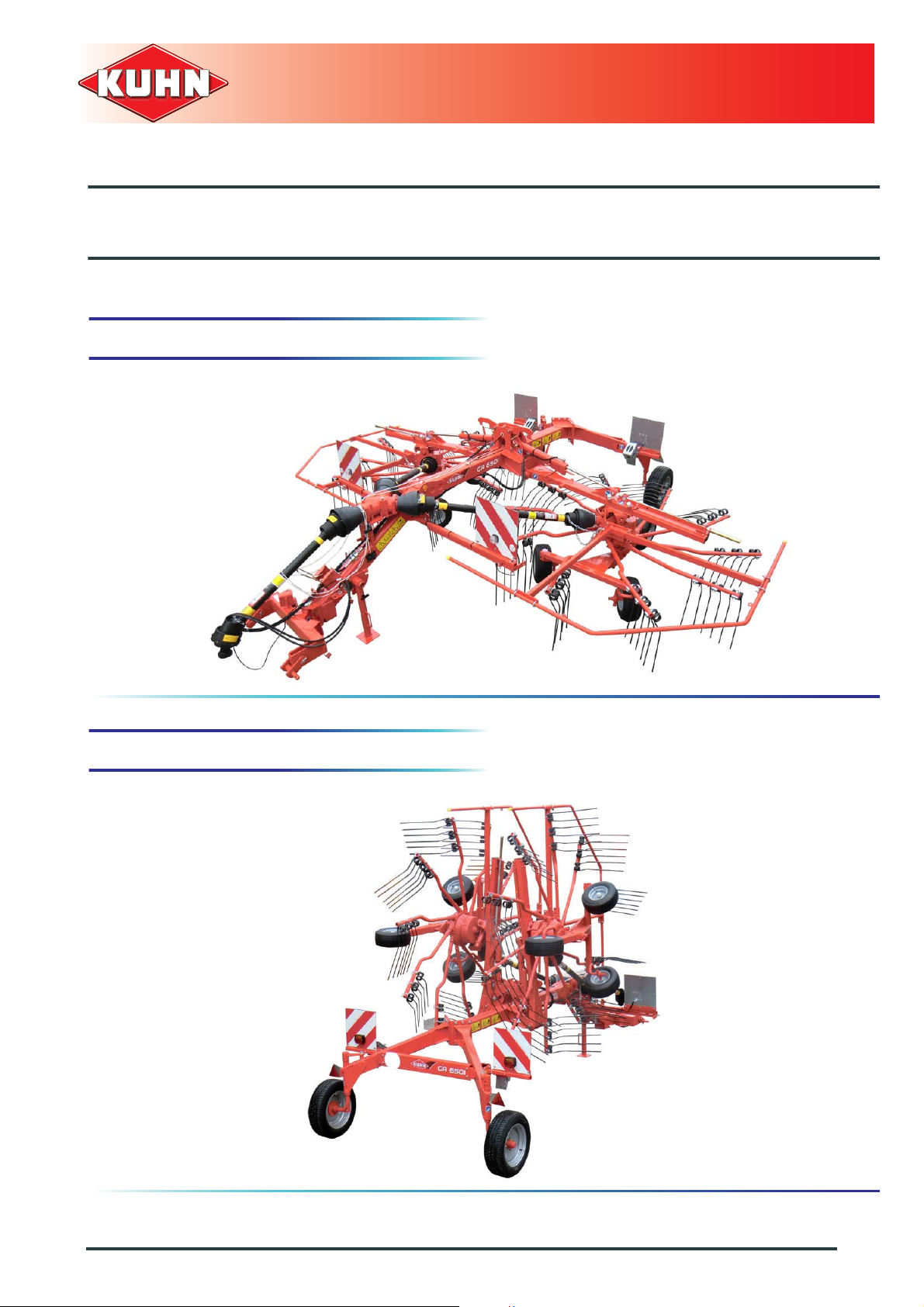
Gyrorake
2. Contents
1. Dear Owner .....................................................................................................................1
2. Contents..........................................................................................................................2
3. Identification of the machine.........................................................................................5
3.1 Front view (working position)........................................................................................................... 5
3.2 Rear view (transport position)..........................................................................................................5
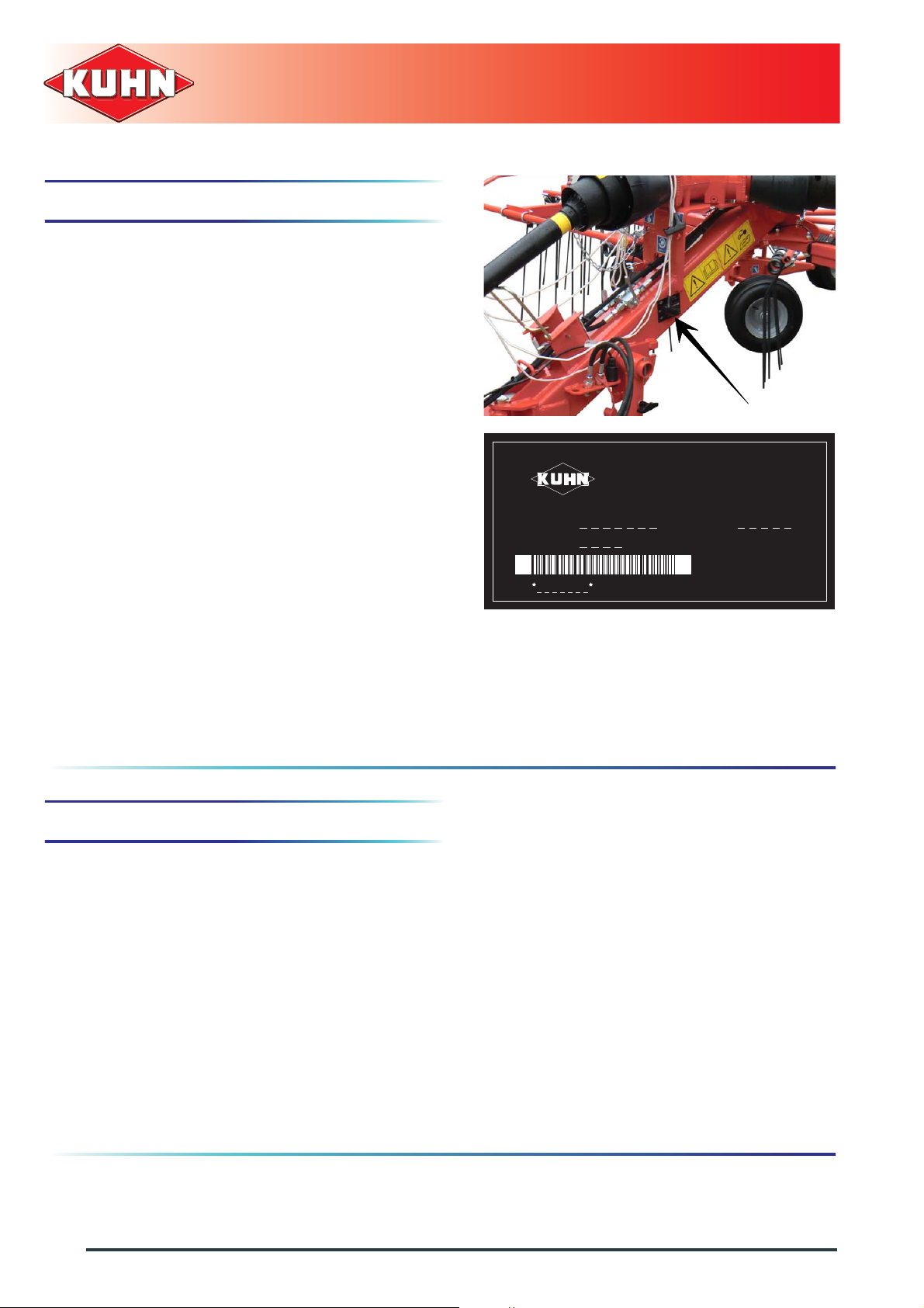
3.3 Model identification plate ................................................................................................................. 6
3.4 Optional equipment.......................................................................................................................... 6
4. Safety...............................................................................................................................7
4.1 Description of symbols used in this document.................................................................................7
4.2 Safety instructions ...........................................................................................................................8
4.2.1 Introduction......................................................................................................................... 8
4.2.2 Read and follow the safety instructions..............................................................................8
4.2.3 Precautions to be taken before carrying out any operations on the machine..................... 8
4.2.4 Precautions to take before using the machine ................................................................... 9
4.2.5 Precautions when driving ...................................................................................................9
4.2.6 Precautions when driving on public roads........................................................................10
4.2.7 Maximum speed................................................................................................................11
4.2.8 Precautions when coupling...............................................................................................12
4.2.9 Hydraulic circuit................................................................................................................12
4.2.10 PTO shaft..........................................................................................................................13
4.2.11 Precautions during manoeuvres....................................................................................... 14
4.2.12 Remote controlled components........................................................................................15
4.2.13 Tyres.................................................................................................................................15
4.2.14 Safety decals.................................................................................................................... 15
4.2.15 Waste disposal .................................................................................................................15
4.2.16 Precautions for maintenance and repair work.................................................................. 16
4.2.17 Projection of stones and foreign objects........................................................................... 16
4.2.18 Precautions for machine use............................................................................................ 17
4.3 Location and description of safety decals on the machine ............................................................ 18
4.3.1 Location of safety decals..................................................................................................18
4.3.2 Description of safety decals.............................................................................................. 19
4.4 Road safety equipment and recommendations ............................................................................. 21
4.4.1 Tyre pressure.................................................................................................................... 22
4.4.2 Instructions specific to France.......................................................................................... 22