manuals.online logo
Brands
  1. Home
  2. •
  3. Brands
  4. •
  5. Premio
  6. •
  7. Network Storage Server
  8. •
  9. Premio eDrawer4072S User manual

Premio eDrawer4072S User manual

Other Premio Network Storage Server manuals

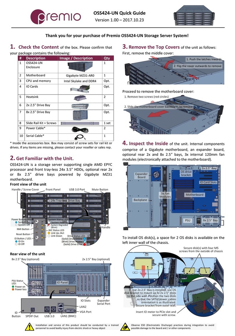
Premio OSS424-UN User manual

Premio

Premio OSS424-UN User manual

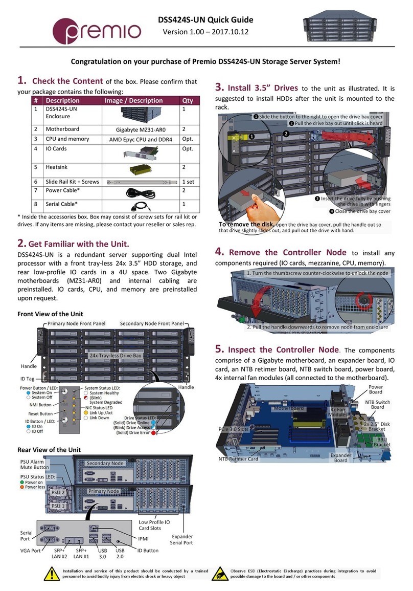
Premio DSS424S-UN User manual

Premio

Premio DSS424S-UN User manual

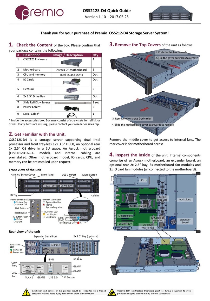
Premio OSS212S-D4 User manual

Premio

Premio OSS212S-D4 User manual

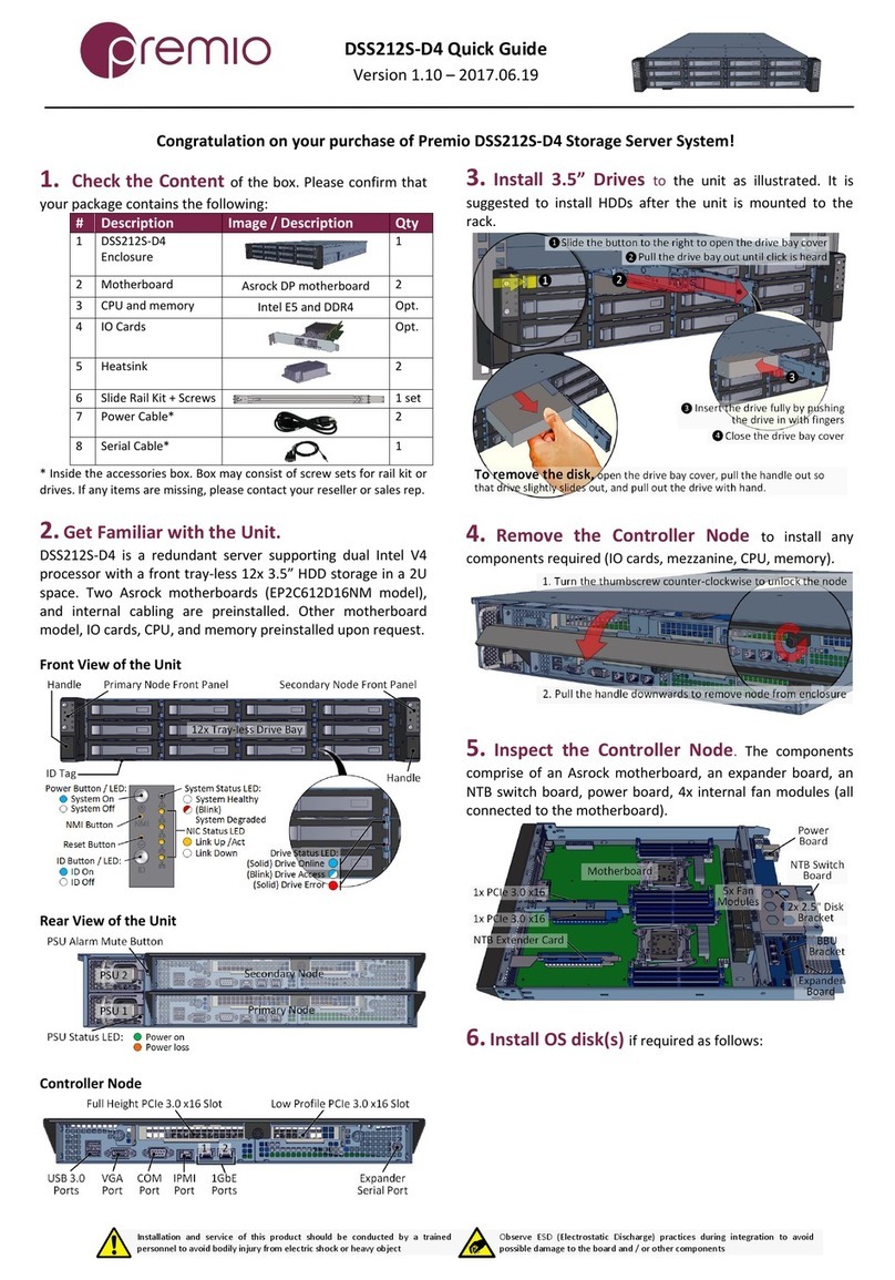
Premio DSS212S-D4 User manual

Premio

Premio DSS212S-D4 User manual

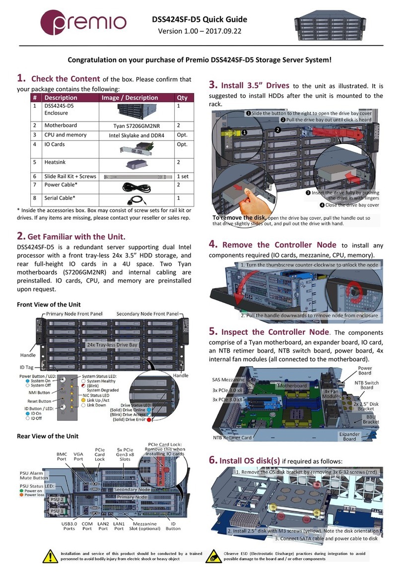
Premio DSS424SF-D5 User manual

Premio

Premio DSS424SF-D5 User manual

Premio FlacheSAN1L-D4 User manual

Premio

Premio FlacheSAN1L-D4 User manual

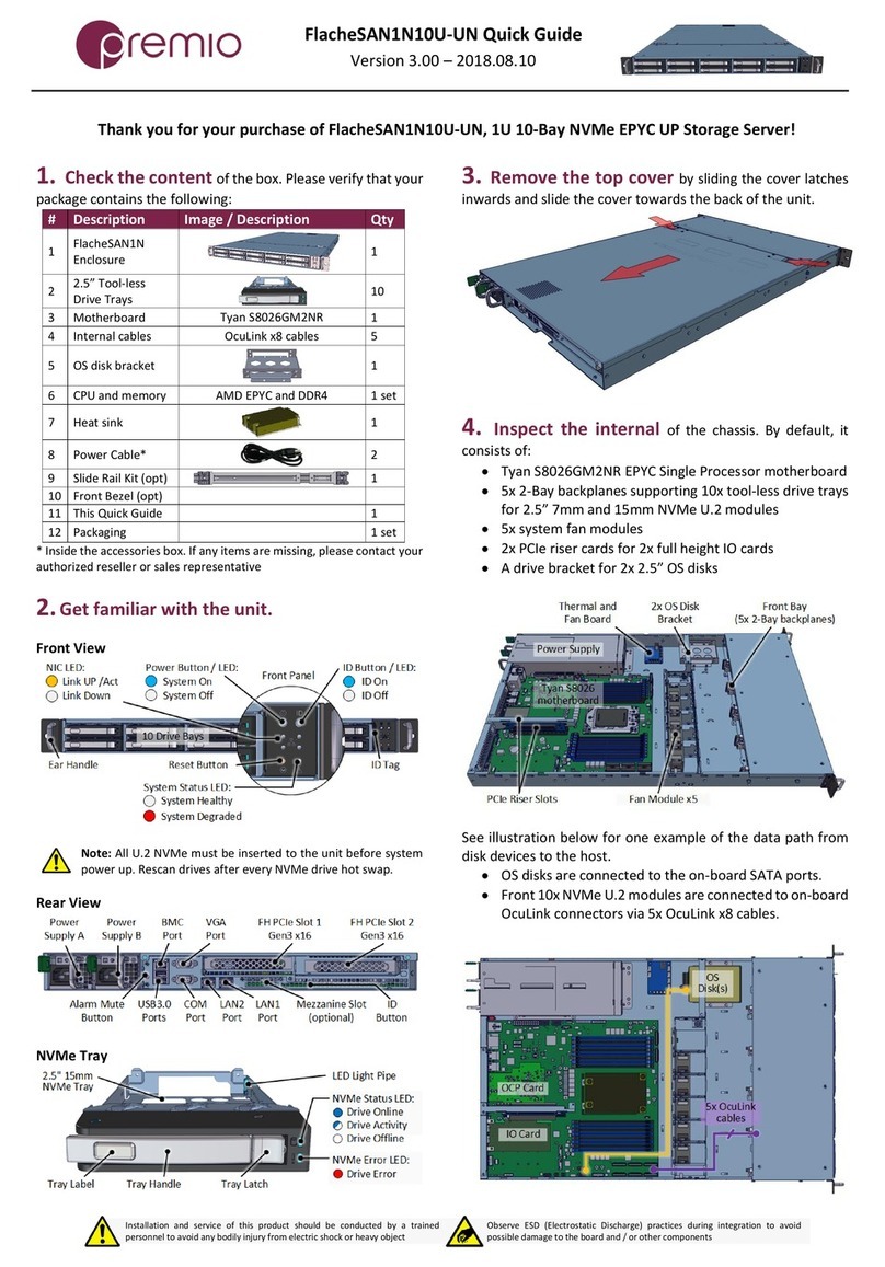
Premio FlacheSAN1N10U-UN User manual

Premio

Premio FlacheSAN1N10U-UN User manual

Premio OSS424S-D4 User manual

Premio

Premio OSS424S-D4 User manual

Premio FlacheSAN1N6C-D4 User manual

Premio

Premio FlacheSAN1N6C-D4 User manual

Premio FlacheSAN2-D5 User manual

Premio

Premio FlacheSAN2-D5 User manual

Premio FlacheSAN1N4C-D4 User manual

Premio

Premio FlacheSAN1N4C-D4 User manual

Popular Network Storage Server manuals by other brands

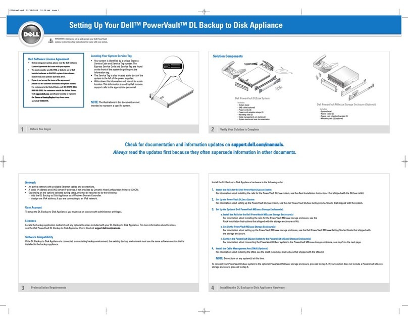
Dell PowerVault DL2100 Setting up

Dell

Dell PowerVault DL2100 Setting up

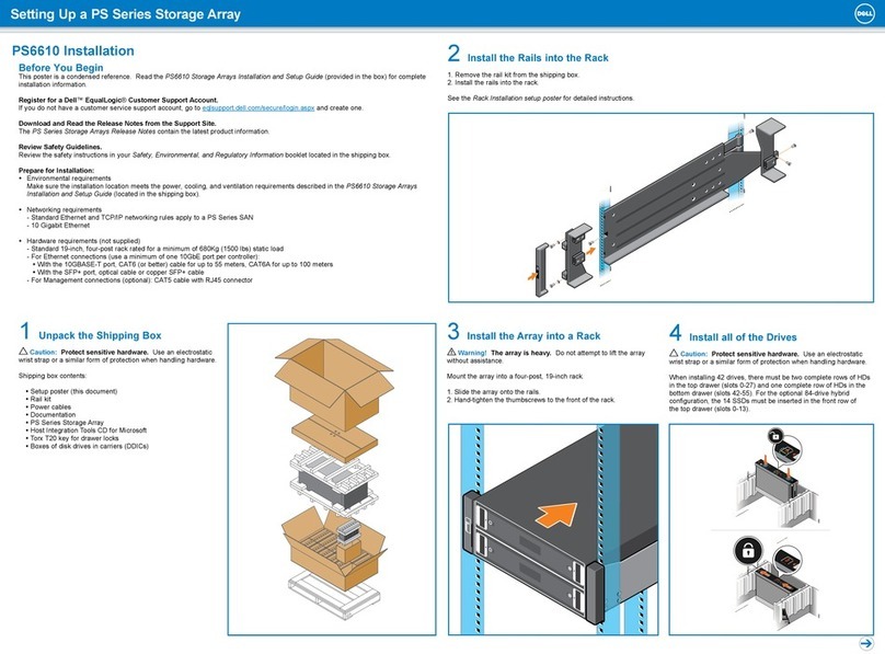
Dell PS Series Setting up

Dell

Dell PS Series Setting up

HP NetStorage 6000 user guide

HP

HP NetStorage 6000 user guide

Synology RackStation RS816 Hardware installation guide

Synology

Synology RackStation RS816 Hardware installation guide

D-Link ShareCenter Pro DNS-1200-05 user manual

D-Link

D-Link ShareCenter Pro DNS-1200-05 user manual

Avid Technology VideoRAID ST Setup and user guide

Avid Technology

Avid Technology VideoRAID ST Setup and user guide

Western Digital My Cloud Home Duo user manual

Western Digital

Western Digital My Cloud Home Duo user manual

PrimeArray 4xxx user guide

PrimeArray

PrimeArray 4xxx user guide

AIC FB128-LX user manual

AIC

AIC FB128-LX user manual

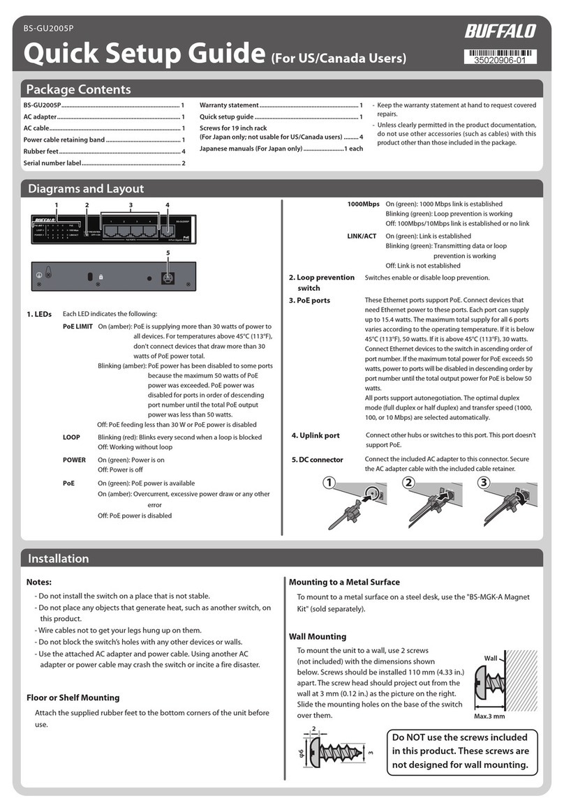
Buffalo BS-GU2005P Quick setup guide

Buffalo

Buffalo BS-GU2005P Quick setup guide

Buffalo TeraStation 5200 Specifications

Buffalo

Buffalo TeraStation 5200 Specifications

QNAP TR-004U Quick installation guide

QNAP

QNAP TR-004U Quick installation guide

LG N2R1DB2 instruction manual

LG

LG N2R1DB2 instruction manual

Seagate NAS 440 Reviewer's guide

Seagate

Seagate NAS 440 Reviewer's guide

QNAP TS-110 Specifications

QNAP

QNAP TS-110 Specifications

Planex MZK-NAS01SG user manual

Planex

Planex MZK-NAS01SG user manual

ASUSTOR AS6508T Quick installation guide

ASUSTOR

ASUSTOR AS6508T Quick installation guide

IOGear BOSS GNS1000  GNS1000 GNS1000 user manual

IOGear

IOGear BOSS GNS1000 GNS1000 GNS1000 user manual

manuals.online logo
manuals.online logoBrands
  • About & Mission
  • Contact us
  • Privacy Policy
  • Terms and Conditions

Copyright 2025 Manuals.Online. All Rights Reserved.

Installation and service of this product should be conducted by a trained
personnel to avoid bodily injury from electric shock or heavy object
Observe ESD (Electrostatic Discharge) practices during integration to avoid
possible damage to the board and / or other components
eDrawer4072S Quick Guide
Version 2.20 –2017.05.09
1. Check the content of the box. Please confirm that your
package contains the following:
#
Description
Image / Description
Qty
1
eDrawer4072S
Enclosure
1
2
Motherboard
Intel S2600TP
1
3
Heatsink
2
4
2.5” Drive Trays
(optional)
8
5
Power Cable*
2
6
Serial Cable*
1
7
Rail Kit
2 sets
8
Cable
Management Arm
Kit
1 set
9
Chassis Handles*
2
10
SAS cables (opt.)
SFF 8644-8644 / SFF 8088-8644
2
11
This Quick Guide
1
12
Packaging
1 set
* Inside the accessories box. If any items are missing, please contact
your authorized reseller or sales representative
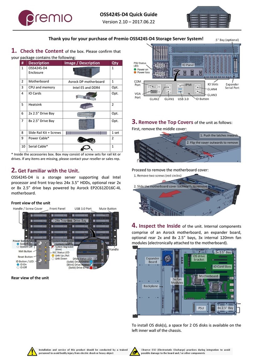
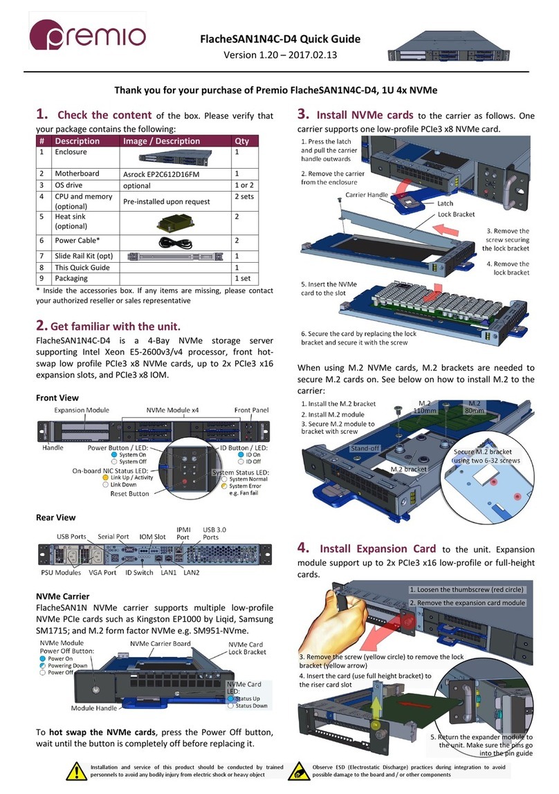
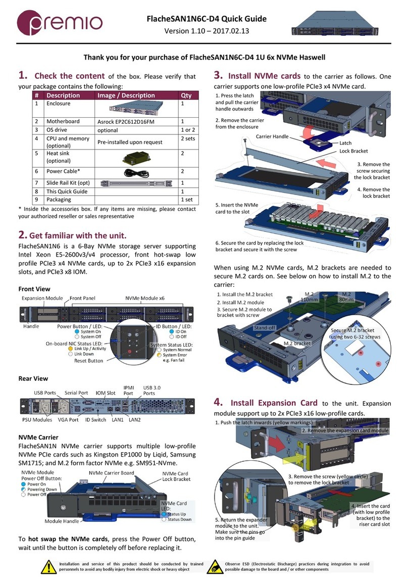
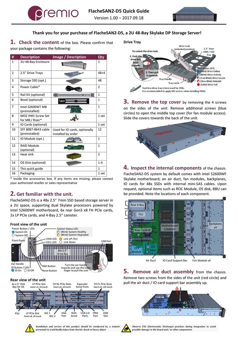
2. Get familiar with the unit.
eDrawer4072S is a 72-Bay storage server powered by Intel S2600TP
dual-processor E5 Haswell motherboard.
Front view of the unit
Rack Screw
Hole
Ear Handle
Latch for
MB Cover
Latch for Drive
Bay Cover
Key Lock for
the Latches
Front Panel
Reset Button
Drive Status LEDs
for Bay 1-72
Drive Status LEDs for
8x 2.5" Rear Drive Bay
Power Button
(Blink) Drive Activity
(Solid) Drive Fail
(Blink) Drive Missing
(Solid) Drive Online
Drive Status LED:
Top Cover for Drive Bay
Top Cover for
Motherboard
Motherboard
(Solid) RAID Drive
(Blink Purple on Solid Blue) RAID Activity / Rebuild
(Alternating Blink) Drive Fault / RAID Failure
(Blink) Drive Locate Drive Offline/ Removed
LP PCIe Gen3 x8 slot
Rear view of the unit
Power Switch
Power Supply
Module 1
Power Supply
Module 2
Expander Board
PSU Alarm
Mute Button
Fan 1 Fan 3 Fan 5
Fan 2 Fan 4 Fan 6
RAID Controller
or HBA
SAS Down Link Ports:
• Top for Bay 1-36
• Bottom for Bay 37-72
Handle for PS
Module
PSU Status
LED
Handle for
Fan Module
Serial Port
AC Receptacle
8x 2.5" Bay
(optional)
IO Panel
3. Open the Drive Cover of the unit reveals the drive slots.
1. Use the key to unlock the latch
2. Slide the right latch inwards
3. Unscrew the thumbscrews (red circles)
4. Lift the drive cover up
5. Support rod will slide to lock the cover open
4. Open the Controller Cover as follows to reveal the
motherboard, fan modules, OS drives and IO cards:
5. Inspect the Internal components under the hoods.
Expander boards are located between drive slot and controller.
Drive Slots for
Front Bay 1 – 36
(3 rows of 12 drive slots)
Drive Slots for
Rear Bay 37 – 72
(3 rows of 12 drive slots)
2x Drive Slots
for OS disk(s)
Fan moduleMotherboard
Rear ExpanderFront Expander
Riser Card for
IO Card
Front expander controls the first front 36 disks, the rear expander
controls the last 36 disks. The internal RAID/HBA manages the drives for
the OS to see all 72 disks.
Above is the specification of the motherboard used for eDrawer4072S.
eDrawer4072S Enclosure Quick Guide
For more information please visit our website at www.Premioinc.com
Copyright © 2017,Premio Inc. All rights reserved.
See diagram below for the interconnection between boards.
S2600TP
Motherboard
SAS
Expansion
Ports
PCIe Gen3 x8 Riser Card
Backplane to Rear ExpanderBackplane to Front Expander
2
Front Expander Path
OS
Disks
Rear Expander
Front Exp.
RAID/HBA
PCIe Gen3 x8 Riser Card
IO Card
Rear Expander Path
IO Path
Rear 8-Bay
6. Install the Enclosure to the Rack. Refer to
eDrawer4072S Rack Mounting Guide for details.
Caution: At least two people are required to lift the chassis.
7. Install Drives to the enclosure. Pull the enclosure from the
rack and open the top cover(s).
1. Open the drive
tray cover
3. Insert 3.5" HDD
4. Align the drive screw holes (yellow
circles) with the nubs (yellow arrows)
2. Pull the drive tray slightly
until click is heard
Caution: HDD tray orientations are opposite for every other rows. Be
cautious when installing the drive trays.
It is recommended to install drives per row, to ensure the easiness of
inserting the tool-less trays back to their slots.
8. Drive Mapping of the enclosure is as follows:
1
12
13
24
25 37
36 48 60 72
49
Note that the orientation of the
drive trays change every row
61
Look for Red LED
on the trays to
locate failed drives
9. Establish a Client Connection. The 72-disk volume
(or multiple volumes depending on the RAID configuration) can be
exported through the front LP PCIe Gen3 x8 IO card. SAS, FC, or Ethernet
cables is utilized depending on the IO card and export protocol used.
Connect the cable(s) from the IO card to the client side accordingly. See
below for configuration choices:
Host / Client
IO Adapter
DSS316JeDrawer4072S
Single Client Configuration: Connect an IO cable to a client. The
client will see all drives from eDrawer4072S.
eDrawer4072S
Host / Client
IO Adapter
Host / Client
IO Adapter
Dual Client Configuration: Connect IO cables to discrete clients.
Each client is to see a different set of drive volumes.
eDrawer4078J
eDrawer4072S
Host / Client
IO Adapter
Host / Client
IO Adapter
39
39
Daisy-chain Configuration: Connect SAS cables from the unit’s
expansion ports to a JBOD Up link port (e.g. eDrawer4078J). Each
expansion cable connects to half the storage (39 disks) of
eDrawer4078J. Manage the disks and export accordingly.
10. Plug in the Power Cords to the AC
receptacles on the back of the unit and secure it with
provided cable ties. Turn on the PSU power switch
afterwards.
11. Press the Power Button on the
front of the unit and wait about 30 seconds until the
unit is ready.
Once it’s ready, power up your host unit.
Access the Serial Console (when
necessary) by connecting a serial audio cable to the
debug console port and use a terminal console with
baud rate 38400, 8, N, 1, N.
Type “help –a” for a list of commands.