PREMIUM STRINGER 8900 Electro User manual
0
USER’S MANUAL FOR
STRINGING MACHINE 8900

1
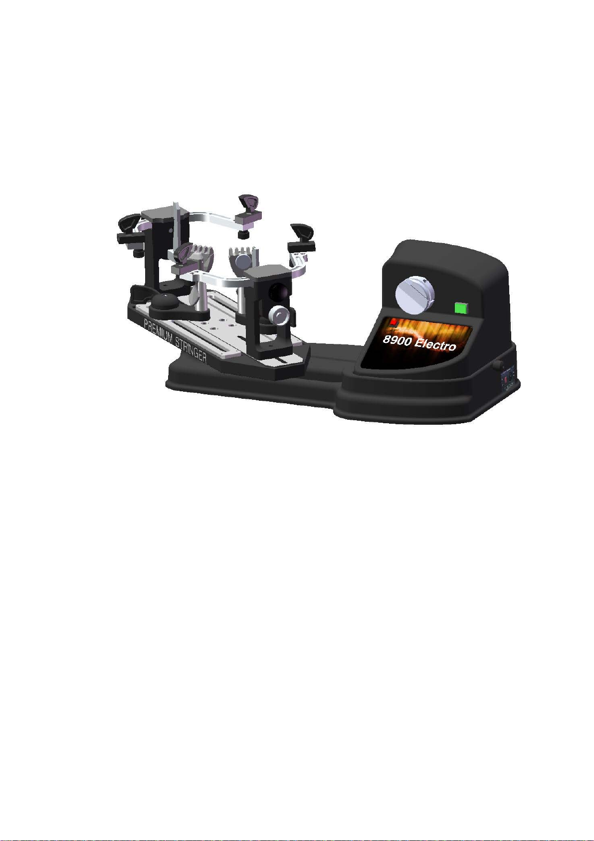
1. ANATOMY
I.
Machine Body
II.
Electronic Parts
1.
Side Support
A.
String Gripper
2.
Side Support Arm
B.
Indicator Lights
3.
Side Support Arm Adjustment Knob
C.
Tension Switch
4.
I-Adpater Center Support
D.
L.E.D. Tension Display
5.
Center Support Adjustment Knob
E.
KG/LB Select Switch
6.
Mounting Stock
F.
Tension Adjustment Knob
7.
Mounting Stock Locking Knob
G.
Gripper Reversing Switch
8.
Turntable
H.
Pre-Stretch
9.
Rail/Track for Turntable
10.
Swivel Clamp
11.
Swivel Clamp Holder
12.
Tool Tray
13.
Lower Housing
14.
Brake
15. Upper Housing
1
3
2
4
5
6
7
9
8
14
B
A
F
D
E
H
10
12
G
M
11
13
C
A
15
2
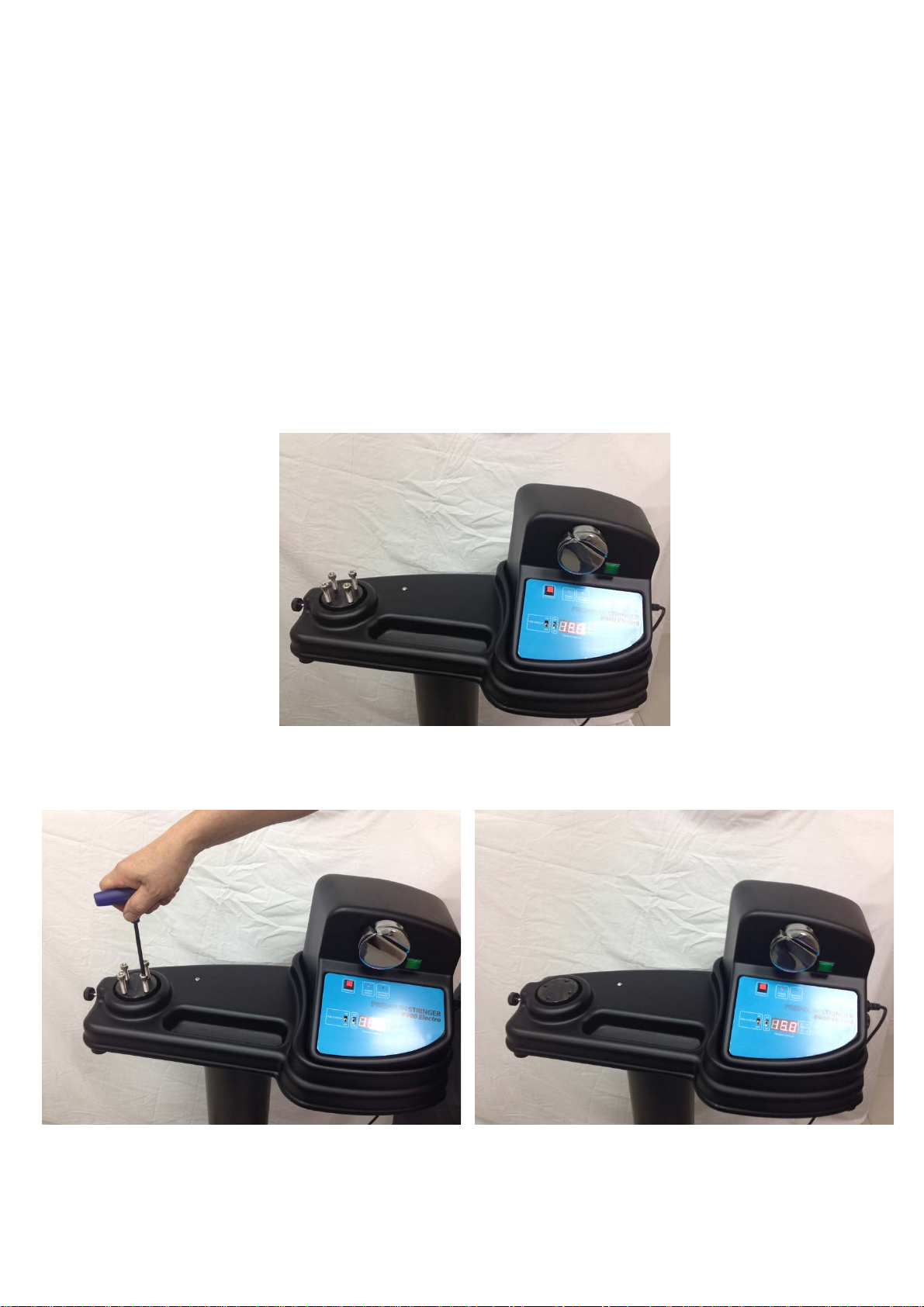
2. INSTALLATION PROCEDURE
The 8900 is shipped to you in two cartons.
Here is what the two cartons contain:
1). Electronic Tension Head
2). Racquet Mount
Open the carton of the tension head.
Carefully lift the tension head assembly out of carton and place it on a hard surface.
Remove the 4 Allen bolts from the bearing pivot of the tension head assembly by
a 6 mm wrench
3
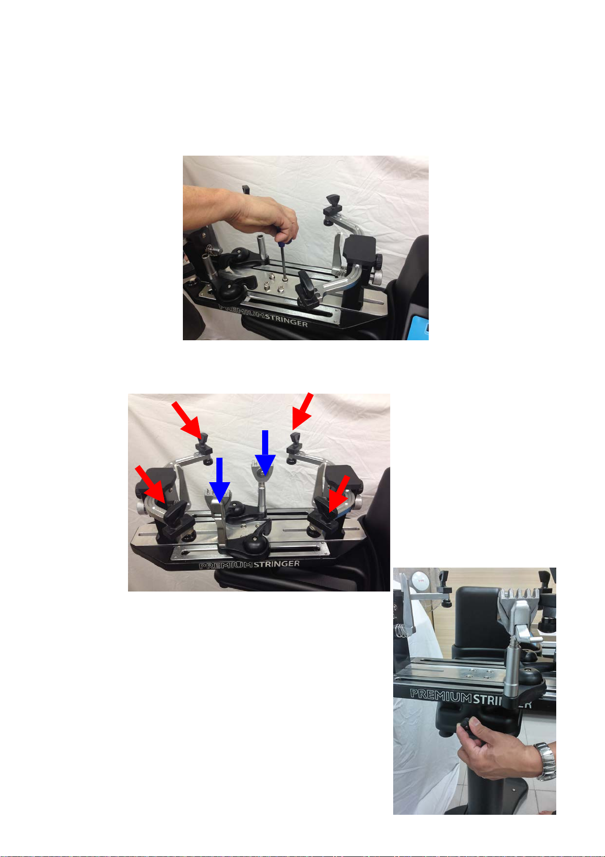
Open the carton of the racquet mount. Carefully lift the racquet mount
assembly out of carton and place its turntable in the bearing pivot of the
tension head assembly. Next insert the 4 Allen bolts in the 4 holes of the
turntable and then tighten them evenly with a 5 mm wrench.
Insert the string clamps into the clamp bases. Mount the each side support in the
proper hole on the side support arms and secure it by tightening its knob beneath.
Unlock the turntable by rotating the screw of the brake
counter-clockwise to release the turntable.

4
4. MOUNTING THE RACQUET FRAME
1. Begin by turning the black (side support adjustment) and chromed (center support
adjustment) knobs on the two mounting stocks counterclockwise to open the side
support arms and reduce the spread of the vertical supports.
2. Spread the mounting stocks so that the vertical centers supports fit within
the racquet head without touching it. The stocks are loosened from below the
turntable.
3. Locate the center points of the racquet at the head and throat and place them
next to the vertical supports on the mounting stocks. The turntable indicate
which stock the head and throat go on.
4. Turn the black side support arm adjustment knobs on each mounting stocks
clockwise to bring the side supports in contact with the racquet at all four points.
Note that the racquet levels and centers itself as the side supports cradle it.
Do not over tighten.
5. Now turn the chromed knob clockwise to tighten the vertical supports.
Ensure that the supports fit between the grommets in the center of the racquet.
Do not over tighten or the racquet may be difficult to remove at the end of
the string job.
An exclusive W-adapter is installed on your 8900 to spread stringing loads over
a wider area of the racquet at the head and throat. In cases where the W-adapter
doesn’t fit between the grommets of tennis racquet frame, it can be replaced with
a traditional straight support (I-adapter).
5
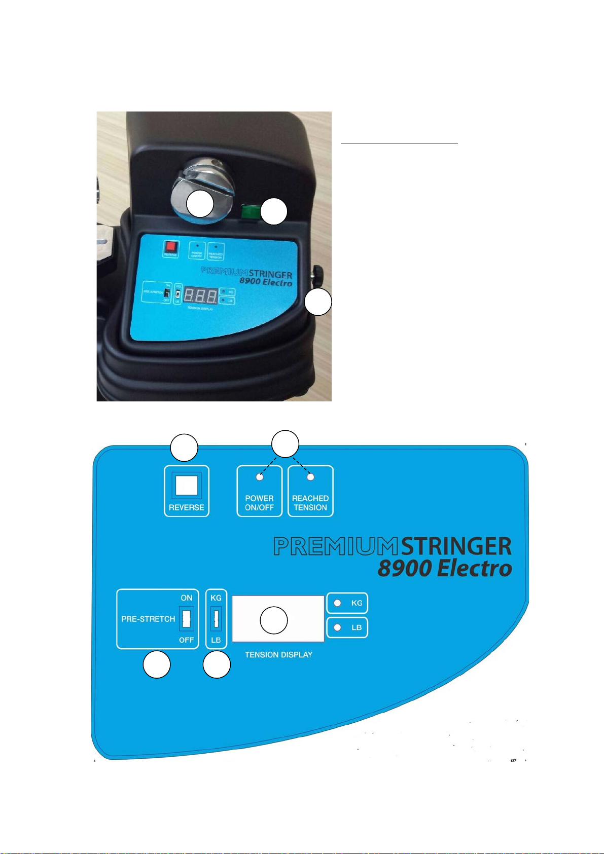
5. TENSION CONTROL :
F
Front Panel Features :
A. Rotary String Gripper
B. Indicator Lights
C. Tension Switch
D. L.E.D. Tension Display
E. KG/LB Select Switch
F. Tension Adjustment Switch
G. Gripper Reversing Switch
H. PRE-STRETCH
B
A
E
C
D
G
H
F

6
Step 1:
To install the power cord, insert the female end of
the power cord into the Power Cord Socket
located on the rear of the tensioner and plug the
male end into a grounded power outlet.
Step 2:
Turn the main power switch on by pressing it in
I direction. (O direction is to turn the tensioner
off.) and the red power indicator light will light
up on the panel. Voltage between 220V and
240V (50 Hz to 60 Hz) is acceptable. NOTE: A
2 amp spare fuse is located in the power cord
receptacle.
Step 3:
Select the KG unit by pushing switch of KG/LB
up and the KG indicator light will light up.
Step 4:
Select the LB unit by pushing switch of KG/LB
down and the LB indicator light will light up.
7
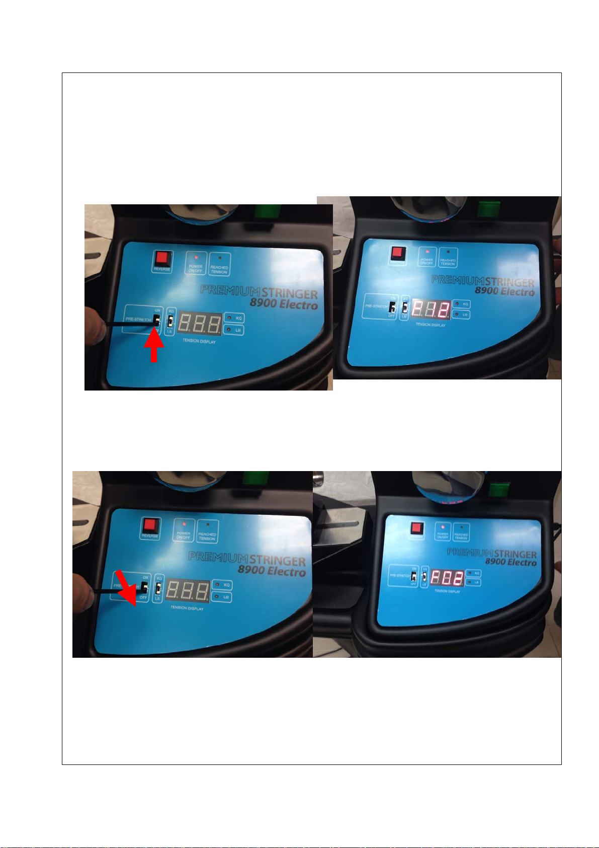
Step 5:
Factory has pre-set the Pre-Stretch before shipment so while switching on the machine by
pressing the Power Switch on the side panel, the LED will display “F12”. If the LED doesn’t
display “F12”, to attain the Pre-Stretch function, switch off the machine by pressing the Power
Switch on the side panel first. Second, turn on the Pre-Stretch Select Switch. Third, switch on the
machine by pressing the Power Switch again and then the L.E.D will display “F12” at start up.
To pull the string without Pre-stretch function, switch off the machine by pressing the Power Switch
on the side panel first. Second, turn off the Pre-Stretch Select Switch. Third, switch on the machine
by pressing the Power Switch again and
then the L.E.D. will display “F02” at start up.
8
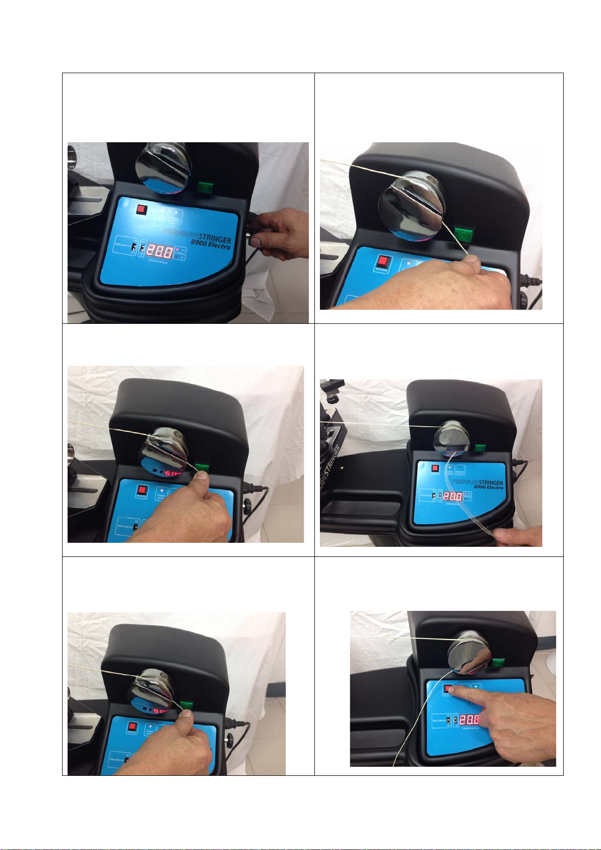
Step 6:
Set the desired tension (such as 20 lbs) by
rotating the tension adjustment knob –
clockwise to decrease the tension and
counterclockwise to increase the tension.
Step 7:
To pull insert the string in the string gripper,
wrap the free end of the string clockwise around
the string gripper and insert the string between
the gripper jaws.
Step 8:
Press the tension switch to motivate the string
gripper to rotate.
Step 9:
After the set tension is attained, the gripper will
stop rotation and the green indicator light will
light up.
Step 10:
To release the string after clamping, press the
tension switch again.
Step 11:
If the string gripper does not release the string
after pressing the tension switch, depress the red
gripper reserving switch once to release the
string.

9
6. Tension Calibration:
Step 1:
Use a calibrator (an electronic calibrator is highly recommended), apply tension as if
stringing a tennis racquet. Note: The calibrator and pulled string must avoid contacting any
parts on the machine as it may cause the friction and get the wrong tension.
(electronic calibrator)
(manual calibrator)
Table of contents
Other PREMIUM STRINGER Stringing Machine manuals


