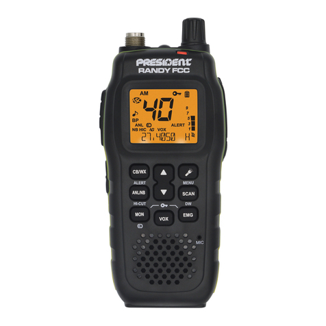
RANDY II/ XH9600E Circuit Description
Randy II / XH9600E are same Low Band VHF radio which is operating from 26.965 ~ 27.405 MHz
frequency range. According to the schematic diagram that separate by several section, the
circuit description are as below:
A.System Description
The radio has built in AM & FM modulation with receiving & transmitting simplex operating function. The
operating frequency had been fixed by MCU. The receiving circuits are designed by double-mixer system
both FM & AM, the 1st intermediate frequency is 10.695MHz & the 2nd intermediate frequency is 455KHz, the
2nd local frequency is 10.24MHz, the audio signal will connect from U2 through AF amplifier (U3) to the
loudspeaker.
The 1st local frequency is generated by VCO (voltage controlled oscillation) that was controlled by MCU (U4)
through PLL chip (U6). The PLL OSC frequency is 10.24MHz which is generate by XA1 crystal, the MCU
clock is built-in type.
The transmission frequency is come from VCO with AM or FM modulation, then through RF PA amplifier (Q1)
& low pass filter (L1~L4) to antenna.
B.Receiver Section
(1) Antenna Low Pass Filter
The low pass filter are used to attenuate the unwanted signal in RX & TX mode, they combine with L1, L2,
L3, L4, L6 & other relative components.
(2) Antenna Switch
The RX/ TX antenna switch are including D1, D2, C15, C21, D4 & R3.
(3) Front End LNA Circuit
They are including band pass filter & LNA amplifier, L8, L10, L11, Q59, L14, L15, L16 are band pass filter
which are allow the desired signal go in only, Q42 is LNA amplifier.
(4) 1ST Mixer & IF Filter
The input signal will be mixed with local OSC signal & generate the 1ST IF 10.695Mhz, they are including
Q5, L17, R95, C130, C66, R10, it will go out through the IF filter XF1.
(5) IF Amplifier & Audio Detect Signal
The 1ST IF signal will go to U2 (including 2nd IF mixer, amplifier, AM/FM detect, --- etc.) pin 20, it will go
through 455KHz ceramic filter FA1 & discriminator Y2, to detect a AF signal out in U2 pin11 (FM) or
Pin14(AM).
(6) Squelch & AGC Circuit
The noise signal go to the noise amplifier input (U2 pin12) & output from U2 pin13, then go to the U1 to get
the noise level & RSSI level, they are used to set the squelch level by MCU & AGC circuit (Q6, Q7).
(7) AM/FM switching & Speaker Amplifier
The AM/FM audio signal will be switch by Q10, Q11, then go in the TIC1 pin23 for CTCSS tone decoder &
audio process, then go to the speaker amplifier (U3) through buffer amplifier (Q8) & volume controller.
C.PLL Frequency Synthesized
The PLL circuit is used to control the VCO to generate the local OSC frequency for receiving &
transmission frequency.
(1) PLL Circuit
